
Circuit Diagram
Index 356
Variable Frequency Switch Mode Regulator
Published:2012/9/4 1:26:00 Author:Ecco | Keyword: Variable Frequency , Switch Mode, Regulator

This voltage regulator circuit operates in switch mode. Using the configuration shown in the schematic diagram, this circuit has variable switching frequency, depends on the input voltage and load condition. The core controller of this switching regulator is a TL497 switching regulator controller IC. Here is the schematic diagram of the circuit: (source: freecircuitdiagram)
When the load is low (draw only small current), this circuit will lower the frequency to give lower active factor, keeping the output voltage at constant level. When the load draw higher current then this regulator circuit will produce higher switching frequency to compensate the faster drop output capacitor (100uF). You can see that the voltage of this output is sense through voltage divider resistors (3.3k and 1.2k), we can tune this resistor to give other than 5V output voltage. A 75% efficiency is possible to achieve with this switching regulator circuit.
(View)
View full Circuit Diagram | Comments | Reading(1869)
Black Light (UV Tube Lamp) Inverter
Published:2012/9/4 1:21:00 Author:Ecco | Keyword: Black Light, UV Tube Lamp, Inverter
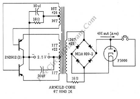
The voltage boosting in this circuit enable its operation to be powered by 2.5 V rechargeable battery (two cells 1.2V rechargeable batteries), supplying 400 mA current at 26 V which is needed by the gas arc tube for portable ultraviolet lamp. This inverter circuit has a good efficiency as well, about 80%. Ultraviolet (UV) light is also known as black light since the light is invisible, but can energize some materials to glow when the materials is exposed to this black light. Money or other security tag is usually checked used this kind of light. Here is the schematic diagram of the circuit: (source: freecircuitdiagram)
(View)
View full Circuit Diagram | Comments | Reading(2321)
Power Saver for Relays
Published:2012/9/4 1:18:00 Author:Ecco | Keyword: Power Saver , Relays

Relays are normally operated at current level where it can initiate the mechanical metal contactors movement. After contacts has been established, the current level needed to keep the conductor plates stay attached is actually smaller than the current to initiate it. This power saver circuit seems to have opposite mechanism of surge protector. This circuit provide surge current to initiate mechanical movement, but after that, this circuit throttle the current to save the power, provide lower current level just to keep the contacts stay attached. Here is the schematic diagram of the circuit:
The mechanism of this circuit is similar but done in opposite way with current surge protector. If we use a varistor with negative coefficient, here we use a kind of varistor but with positive coefficient, where the resistance increases as the temperature increase. This kind of varistor is actually an incandescent bulbs, two bulbs in parallel. At cold temperature, this bulbs has very low resistance, this make sure the relay will has sufficient power supply to initiate the mechanical movement of its contactors. After the relay works, the rise of bulbs temperature will make the current decreased to a lower level, saving the power while maintaining the contactors stay attached. That’s all the mechanism of this power saver circuit.
(source: freecircuitdiagram)
(View)
View full Circuit Diagram | Comments | Reading(1249)
Selectable Voltages 6V, 9V, and 12V Linear Voltage Regulator
Published:2012/9/4 1:16:00 Author:Ecco | Keyword: Selectable Voltages, 6V, 9V, 12V , Linear Voltage Regulator
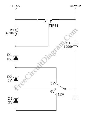
We can build a multiple voltage power supply 6, 9, and 12V (AC-DC Adapter) with the circuit shown in the following schematic diagram. Not only provide multiple voltage output with single voltage supply, this circuit add the benefit of regulating the voltage for better stability. The TIP31 transistor should be installed with proper heat-sink to prevent overheating. A transformer with rectifier diodes and filtering capacitor can be used to supply this circuit. You can use 1 A 15V transformer with 2200uF filtering capacitor for the AC to DC adapter. (source: freecircuitdiagram)
(View)
View full Circuit Diagram | Comments | Reading(2013)
Automotive/Car Power Adapter For 3V, 6V, or 9V DC Operated Devices
Published:2012/9/4 1:14:00 Author:Ecco | Keyword: Automotive, Car Power Adapter , 3V, 6V, 9V, DC Operated Devices
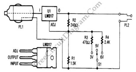
In automotive environment, it’s common that only single voltage power outlet is available. Using the very popular LM317 voltage regulator IC, we can build a general purpose DC adapter to adapt car’s power outlet voltage (12-14 Volts) to supply small DC devices requiring lower voltage level. On the following schematic diagram for the car power adapter, we can see that the output voltage depends on the value of R1, which is manipulated by connecting R3 or R4 via switch to program the output. When connected through the switch, R1 will be in parallel with the selected resistor so the total resistance changes to affect the output voltage.
(View)
View full Circuit Diagram | Comments | Reading(3188)
Three Cells Produce Regulated 3V – 3.3V
Published:2012/9/4 1:11:00 Author:Ecco | Keyword: Three Cells , Regulated 3V – 3.3V
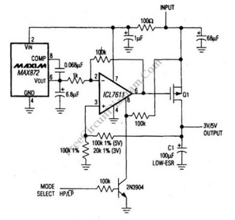
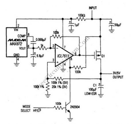
Three NiCad and NiMH batteries can be used to produce 3V/3.3V supply voltage. This can be done by this linear regulator circuit. This circuit uses an ICL7611 micropower op amp and MAX872 voltage reference. This regulator can be used to replace the charge pump or a switching regulator. The dropout characteristics of this circuit depends on the characteristics of Q1. The Q1 must have a gate-threshold voltage below the lowest battery voltage when this circuit is used with low voltage like a three-cell battery. Here is the schematic diagram of the circuit: (source: freecircuitdiagram)
This circuit requires input voltage from 3V to 15V. This circuit has two mode, high power mode and low power mode that can be selected by logic at the MODE SELECT input. With Vin 6.5V, the quiescent current is 70µA when operated in high power mode and decrease to 40µA when it is used in low power mode. This circuit has maximum load power of 5mA in low power mode and 1A in high power mode.
(View)
View full Circuit Diagram | Comments | Reading(1066)
Ni-Cad Battery Zapper, A Rechargeable Battery Reconditioner
Published:2012/9/4 1:09:00 Author:Ecco | Keyword: Ni-Cad Battery Zapper, Rechargeable , Battery Reconditioner

Ni-Cad (NiCd, NiCad) battery, sometimes doesn’t work as expected, gives no power and cannot be recharged. In this situation, the battery need to be reconditioned. It’ is possible that the battery is internally shorted, and we can get the battery into life again by recondition the Ni-Cad battery using a zapper circuit. This circuit restore the Ni-Cad battery from shorting by forcing a high current flow to burn the internal dirt. The current stored in the high capacitance capacitor is heavy discharged by the SCR when zapping, and the SCR is used to disconnect the battery connection when charging the capacitor. A 120 ohm 10W resistor is used to limit the current when charging the capacitor, and you have to make sure the LED’s intensity has reach the steady state before switching to zap position. After zapping the battery and switch to charge position, the charging process will take some period and indicated by the LED which will gradually increase the brightness until get stable intensity when fully charged. The power supply for this circuit can be taken from small transformer (350 mA to 1 A) with half or full wave rectifier. Here is the schematic diagram of the battery zapper circuit: (source: freecircuitdiagram)
(View)
View full Circuit Diagram | Comments | Reading(1254)
Main Power-Battery Backup Switcher
Published:2012/9/4 1:08:00 Author:Ecco | Keyword: Main Power-Battery , Backup Switcher
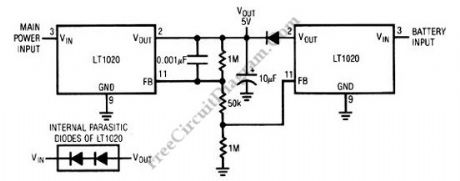
The schematic diagram shown below is a battery backup regulator circuit, useful for memory or other low power (battery operated) but critical circuit (must continue operation on powerline failure). The one LT020 will not conduct in under line-powered condition, made possible by means of of feedback string’s arrangement. In case of main power failure, the battery-driven LT1020 will turn on and maintain the load, when the line LT1020 go off because the line goes down. Here is the schematic diagram of the circuit: (source: freecircuitdiagram)
(View)
View full Circuit Diagram | Comments | Reading(974)
High-Voltage Generator with HEX FET
Published:2012/9/4 1:07:00 Author:Ecco | Keyword: High-Voltage Generator , HEX FET
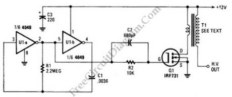
The schematic diagram below show a circuit of high voltage generator. This circuit uses a 4049 hex inverter as an oscillator, and you can use ignition transformer from automotive engine. A fly-back transformer is possibly usable too. The 4049 will drive the IRF731 HEX FET. The Q1 must be heatsinked. Here is the schematic diagram of the circuit: (source: freecircuitdiagram)
(View)
View full Circuit Diagram | Comments | Reading(3217)
TLC497CN Negative Supply Generator
Published:2012/9/4 1:05:00 Author:Ecco | Keyword: Negative Supply Generator
Three NiCad and NiMH batteries can be used to produce 3V/3.3V supply voltage. This can be done by this linear regulator circuit. This circuit uses an ICL7611 micropower op amp and MAX872 voltage reference. This regulator can be used to replace the charge pump or a switching regulator. The dropout characteristics of this circuit depends on the characteristics of Q1. The Q1 must have a gate-threshold voltage below the lowest battery voltage when this circuit is used with low voltage like a three-cell battery. Here is the schematic diagram of the circuit:( source: freecircuitdiagram)
This circuit requires input voltage from 3V to 15V. This circuit has two mode, high power mode and low power mode that can be selected by logic at the MODE SELECT input. With Vin 6.5V, the quiescent current is 70µA when operated in high power mode and decrease to 40µA when it is used in low power mode. This circuit has maximum load power of 5mA in low power mode and 1A in high power mode. (View)
View full Circuit Diagram | Comments | Reading(1143)
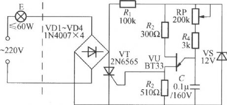
Dimming light circuit with gradually brightening and darkening functions
Published:2012/8/31 1:05:00 Author:Ecco | Keyword: Dimming light, gradually brightening , darkening functions
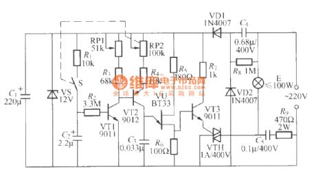
As shown in Figure, itis a novel thyristor dimming light circuit, it not only can used for dimming, and every time when you turn on the light, the light canbe changedfrom dark to bright; when you turn off the light, thelight can be changed frombright to dark gradually.
(View)
View full Circuit Diagram | Comments | Reading(1270)
Four-way flashing light string circuit (9) (M80056B)
Published:2012/8/31 1:17:00 Author:Ecco | Keyword: Four-way, flashing light string
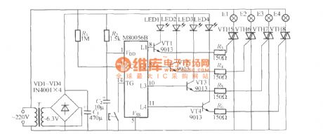
As shown in the figure, it is the high-power eight-figure four-road flashing light string controller with M80056B light controlled IC . VTH1~VTH4 should use 12A/600V thyristors; SB is the switch for lantern string pattern selection, once press SB one time, lantern string changes a cycling pattern.
(View)
View full Circuit Diagram | Comments | Reading(1480)
Multicolor advertising lamp box with emitting music circuit (1)
Published:2012/8/31 2:14:00 Author:Ecco | Keyword: Multicolor, advertising lamp box , emitting music

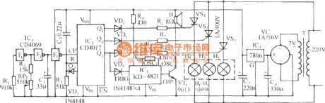
The circuit is shown in the figure. It includes the clock pulse generator, counter/divider circuit, thyristor trigger Lantern circuit, music circuit and AC step-down rectifier circuit and so on. Red, green and blue lights are placed in a glass box, it will emit soft light with three colors of red, green, blue in an order and broadcast world famous music one by one to attract more customer. F1~F3 are three gates of six inverter IC CD4069, and F1, F2 and R1,R2,C1 form a self-excited harmonic oscillator with oscillation frequency is
(View)
View full Circuit Diagram | Comments | Reading(857)
Single-key touching lamp switch circuit (1)
Published:2012/8/30 22:50:00 Author:Ecco | Keyword: Single-key, touching lamp , switch
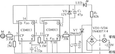
It only uses one electrode M to turn on the light and turn off the light. The core component of the circuit is a dual D trigger digital integrated circuit CD4013, and the wiring method of switch is two-wire system with phase switch, and the swicth can directly replace ordinary mechanical switch without changing the indoor original wiring.
(View)
View full Circuit Diagram | Comments | Reading(2091)
Single-key touching lamp switch circuit (2)
Published:2012/8/30 22:40:00 Author:Ecco | Keyword: Single-key , touching , lamp , switch
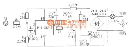
As shown in the figure, it is a single-key touching light switch with voice-activated integrated circuit, it only uses one electrode M to turn on the light and turn off the light. The circuit aAso adopts two-wire connection, it can directly replace the normal mechanical switch.
(View)
View full Circuit Diagram | Comments | Reading(978)
Single-way thyristor dimming light circuit(1) with unijunction transistor trigger
Published:2012/8/30 22:46:00 Author:Ecco | Keyword: Single-way , thyristor , dimming light , unijunction transistor, trigger
In order to improve the stability of voltage onthe lamp, it can use the unijunction transistor trigger circuit shown in the figure.
(View)
View full Circuit Diagram | Comments | Reading(1878)
Single-way thyristor dimming light circuit(2) with unijunction transistor trigger
Published:2012/8/30 22:43:00 Author:Ecco | Keyword: Single-way thyristor, dimming light, unijunction transistor trigger
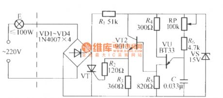
As shown in the figure, VT1 can use 3CT1 or MCR100-8 single-way transistor.
(View)
View full Circuit Diagram | Comments | Reading(2032)
Single-button digital dimmer light circuit
Published:2012/8/30 20:56:00 Author:Ecco | Keyword: Single-button , digital, dimmer light
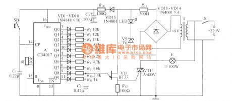
It uses the thyristor trigger circuitcomposed ofCD4017 digital circuitand single-junction transistor,and it hadten block ofadjustable brightness, it is easy to use.
(View)
View full Circuit Diagram | Comments | Reading(3368)
Single-way flashing light string circuit (1)
Published:2012/8/30 21:06:00 Author:Ecco | Keyword: Single-way, flashing light string

As shown in the figure, it is a simple single-way flashing light string controller which is easy to make, it can make the light string gap flash, so itcan be usedfor store or home decoration.
(View)
View full Circuit Diagram | Comments | Reading(1024)
Single-way flashing light string circuit (2)
Published:2012/8/30 21:13:00 Author:Ecco | Keyword: Single-way, flashing light string
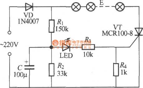
As shown in the figure, it is a simple single-way flashing light string controller which is easy to make, and it is mainly composed of novelty flashing light-emitting diode as core component.
(View)
View full Circuit Diagram | Comments | Reading(1248)
| Pages:356/2234 At 20341342343344345346347348349350351352353354355356357358359360Under 20 |
Circuit Categories
power supply circuit
Amplifier Circuit
Basic Circuit
LED and Light Circuit
Sensor Circuit
Signal Processing
Electrical Equipment Circuit
Control Circuit
Remote Control Circuit
A/D-D/A Converter Circuit
Audio Circuit
Measuring and Test Circuit
Communication Circuit
Computer-Related Circuit
555 Circuit
Automotive Circuit
Repairing Circuit