
Circuit Diagram
Index 351
125KHz Wireless Smart Key Detector
Published:2012/9/5 20:57:00 Author:Ecco | Keyword: 125KHz, Wireless, Smart Key, Detector

This circuit will turn on an indicator light whenever it detects a smart car key containing an RFID chip.
Source: discovercircuits (View)
View full Circuit Diagram | Comments | Reading(3699)
Star Trek Doorbell
Published:2012/9/5 20:56:00 Author:Ecco | Keyword: Star, Trek Doorbell
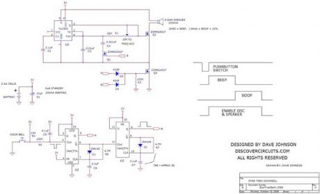
In the Star Trek ?Next Generation? TV series, the doorbell outside the private quarters of a crew member makes a particular ?beep-boop? sound. The 3v battery powered circuit below tries to simulate this sound. The circuit uses one 74HCT74 dual D flip/flop IC, wired as two one-shot circuits. Both are designed to produce a pulse about one half second long. The first pulse turns on a 555 timer to form the beep sound.
Source: discovercircuits (View)
View full Circuit Diagram | Comments | Reading(2017)
Low Power Oscillator
Published:2012/9/5 20:55:00 Author:Ecco | Keyword: Low Power, Oscillator
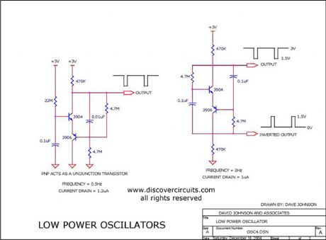
This page has two unusual two-transistor oscillators. I set the component values for a low frequency application. Both circuits draw only about 1 microamp of current.
Source: discovercircuits (View)
View full Circuit Diagram | Comments | Reading(1447)
On/Off Flip/flop Circuit with Automatic Timeout
Published:2012/9/5 20:54:00 Author:Ecco | Keyword: On/Off, Flip/flop , Automatic Timeout
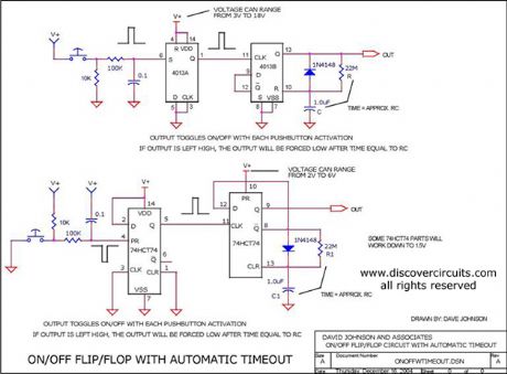
This circuit is ideal when a device needs to be turned on and off with a single pushbutton switch, but also needs to turn itself off after some period of time. With the components shown, the output will stay on for only about 20 seconds.
Source: discovercircuits (View)
View full Circuit Diagram | Comments | Reading(1396)
LONG PERIOD COMPUTER WATCH DOG TIMER
Published:2012/9/5 20:53:00 Author:Ecco | Keyword: LONG PERIOD, COMPUTER WATCH DOG, TIMER
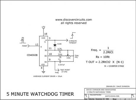
This circuit uses a simple 4060 IC oscillator/timer that is reset periodically by a computer. Should the computer fail to send a pulse, the output changes state. The time can easily be set from seconds to hours.
Source: discovercircuits (View)
View full Circuit Diagram | Comments | Reading(3082)
CMOS SCHMITT TRIGGER IC MAKES VCO
Published:2012/9/5 20:52:00 Author:Ecco | Keyword: CMOS , SCHMITT TRIGGER , IC, VCO
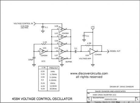
By changing the supply voltage fed to a classic 4584 Schmitt trigger type oscillator, the oscillator frequency can be changed over a range of 50:1. A 74HCU04 inverter is used at the output of the 4584 to maintain a constant TTL logic level signal.
Source: discovercircuits (View)
View full Circuit Diagram | Comments | Reading(1568)
THREE VOLT LOW BATTERY VOLTAGE FLASHER
Published:2012/9/5 20:51:00 Author:Ecco | Keyword: THREE VOLT , LOW BATTERY VOLTAGE, FLASHER
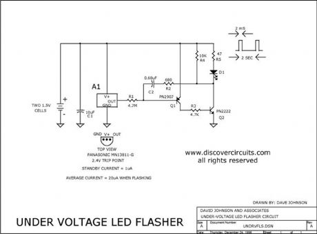
This circuit is designed to monitor two alkaline cells (3v) that form the battery often used in portable electronic equipment. It use an inexpensive IC from Panasonic that is connected to an efficient LED flashing circuit. When the battery voltage drops below a certain point the circuit flashes the LED.
Source: discovercircuits (View)
View full Circuit Diagram | Comments | Reading(2242)
AC Line Under/Over Voltage Alarm (March 29, 2009)
Published:2012/9/5 20:51:00 Author:Ecco | Keyword: AC Line , Under/Over Voltage, Alarm

Power lines, which deviate much beyond normal voltages can damage expensive electronic equipment. The circuit below sounds an alarm whenever the line voltage is higher or lower than normal. I set the alarm limits at about +-15% from standard levels. The circuit rectifies and filters the power line signal. I set the resistor values, so the DC voltage produced is close to 1% of the RMS value of the line. Thus, a 120vac line would yield about 1.2v DC. That voltage is fed to a pair of voltage comparators.
Source: discovercircuits (View)
View full Circuit Diagram | Comments | Reading(2547)
Solar PV cell Test Fixture
Published:2012/9/5 20:45:00 Author:Ecco | Keyword: Solar, PV cell, Test Fixture
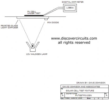
This is an illustration of a test fixture, which can be used to test individual solar cells for short circuit current. Using a PIN photo diode and a control circuit, the solar cells can be tested under constant light level conditions. A halogen incandescent lamp is used as the light source
Source: discovercircuits
(View)
View full Circuit Diagram | Comments | Reading(912)
CIRCUIT PROTECTS FROM BATTERY POLARITY REVERSAL
Published:2012/9/5 20:44:00 Author:Ecco | Keyword: CIRCUIT , PROTECTS , BATTERY POLARITY REVERSAL
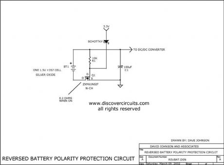
This simple circuit can protect a sensitive electronic circuit from an accidental connection of a battery with a reversed polarity. The N-channel FET connects the electronic device to the battery only when the polarity is correct. The circuit shown was designed for a device powered from a single 1.5 volts button cell battery. However, the circuit will operate with higher voltages as well.
Source: discovercircuits (View)
View full Circuit Diagram | Comments | Reading(1283)
WATER SEEPAGE ALARM
Published:2012/9/5 20:44:00 Author:Ecco | Keyword: WATER SEEPAGE, ALARM
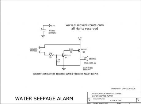
This simple circuit sounds a beeper when its electrodes detect water. It is powered by a single 1.5v N cell. A small 1.5v button battery will also work.
Source: discovercircuits (View)
View full Circuit Diagram | Comments | Reading(0)
Water Flowing in Pipe Indicator
Published:2012/9/5 20:43:00 Author:Ecco | Keyword: Water Flowing , in Pipe , Indicator
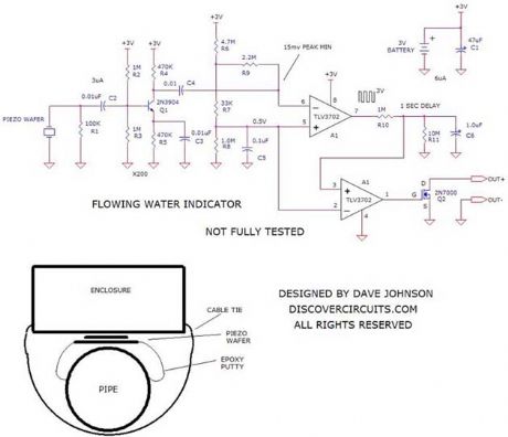
The vibrations associated with water flowing through a pipe are picked up by an inexpensive piezoelectric wafer. The signal from the wafer is first boosted by a micropower transistor amplifier and then fed to an ultra low power voltage comparator. When the vibration signal has sufficient amplitude, a FET transistor switch is activated. Drawing only 6uA, the whole circuit is powered by a lithium coin battery, which should power the circuit for many years.
Source: discovercircuits (View)
View full Circuit Diagram | Comments | Reading(1152)
Electrodeless Water Level Monitor
Published:2012/9/5 20:43:00 Author:Ecco | Keyword: Electrodeless, Water Level , Monitor
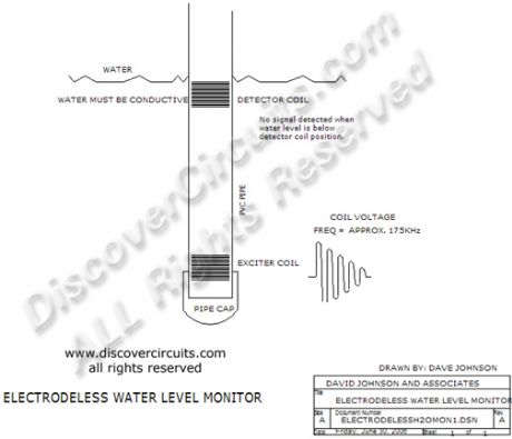
This system operates much like a classic float switch but without any moving parts. The illustration shows how a system using two copper coils sealed inside a plastic pipe, can detect the level of water outside the pipe. Whenever the water level is lower than the upper coil, no signal is coupled between the coils. Once calibrated, this technique might also work on the outside of a plastic water tank.
Source: discovercircuits (View)
View full Circuit Diagram | Comments | Reading(1704)
1 LINE TELEPHONE LINE STATUS INDICATOR
Published:2012/9/5 20:42:00 Author:Ecco | Keyword: 1 LINE, TELEPHONE LINE , STATUS INDICATOR
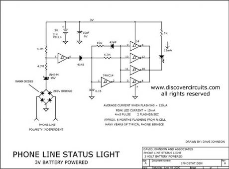
This circuit is similar to the above circuit, but only monitors one phone line.
Source: discovercircuits (View)
View full Circuit Diagram | Comments | Reading(1929)
On/Off Latch Circuit 6
Published:2012/9/5 20:41:00 Author:Ecco | Keyword: On/Off Latch
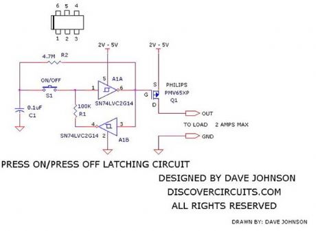
Often you want to turn on and off power to a device with a single pushbutton switch. The circuit below performs this logic function with just a few tiny parts and can operate from DC supplies between +2v and 5v. It uses two inverters within a 6 pin SN74LVC2G14 device from Texas Instruments. Each press of the button toggles between the two on/off logic states. The logic output is connected to a PMV65XP p-channel FET from Philips. This component should be able to handle 2 amps of current
Source: discovercircuits (View)
View full Circuit Diagram | Comments | Reading(3474)
Low Voltage Latching Relay Driver
Published:2012/9/5 20:40:00 Author:Ecco | Keyword: Low Voltage, Latching, Relay , Driver
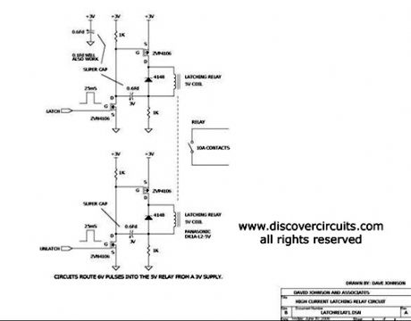
Using some small super capacitors, this circuit can latch and unlatch a mechanical relay with 10 amp contacts, from a small 3 volt power source. By using a latching relay, power can be controlled to a load with a tiny battery.
Source: discovercircuits (View)
View full Circuit Diagram | Comments | Reading(3452)
VOLTAGE TO FREQUENCY CONVERTER + 1uS LED PULSE DRIVER
Published:2012/9/5 20:39:00 Author:Ecco | Keyword: VOLTAGE TO FREQUENCY, CONVERTER , + 1uS , LED PULSE DRIVER
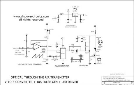
This circuit receives the signal from the above amplifier and launches powerful 1uS infrared light pulses from a low cost LED that are frequency modulated by the audio information. The 10KHz center frequency of the pulse stream is low enough so a standard infrared LED can emit ten times more light than conventional long pulse techniques. The circuit is described in more detail in the transmitter section of my Handbook of Optical Through the Air Communications.
Source: discovercircuits (View)
View full Circuit Diagram | Comments | Reading(1410)
0.5V Negative Supply
Published:2012/9/5 20:39:00 Author:Ecco | Keyword: 0.5V , Negative Supply
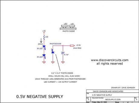
Although not very efficient, this simple circuit, consisting of two LEDs and a photo diode, generates a negative voltage with a current level of a couple milliamps. It is ideal for supplying a negative rail to low power ?rail to rail? op amp circuits, which need to have a true zero volts output.
Source: discovercircuits (View)
View full Circuit Diagram | Comments | Reading(910)
4-20ma Current Loop Tester
Published:2012/9/5 20:36:00 Author:Ecco | Keyword: 4-20ma, Current Loop , Tester
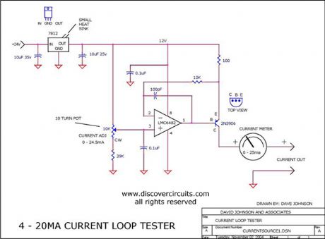
This circuit injects an adjustable current through a wire loop. Using a digital current meter, the current can be adjusted from near zero to over 24 milliamps.
Source: discovercircuits (View)
View full Circuit Diagram | Comments | Reading(7657)
AC Current Controls Hour Meter
Published:2012/9/5 20:36:00 Author:Ecco | Keyword: AC Current, Controls , Hour Meter
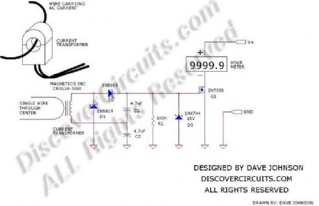
Many systems require routine maintenance based on machine operation time. The circuit below is a simple way to turn on a hour meter whenever AC power is supplied to the machine. An inexpensive snap-on current transformer from Magnetics Inc, is used to detect the AC current.
Source: discovercircuits (View)
View full Circuit Diagram | Comments | Reading(3118)
| Pages:351/2234 At 20341342343344345346347348349350351352353354355356357358359360Under 20 |
Circuit Categories
power supply circuit
Amplifier Circuit
Basic Circuit
LED and Light Circuit
Sensor Circuit
Signal Processing
Electrical Equipment Circuit
Control Circuit
Remote Control Circuit
A/D-D/A Converter Circuit
Audio Circuit
Measuring and Test Circuit
Communication Circuit
Computer-Related Circuit
555 Circuit
Automotive Circuit
Repairing Circuit