
Circuit Diagram
Index 352
555 Timer Forms Simple PWM Motor Controller
Published:2012/9/5 20:35:00 Author:Ecco | Keyword: 555 , Timer Forms , Simple , PWM , Motor Controller
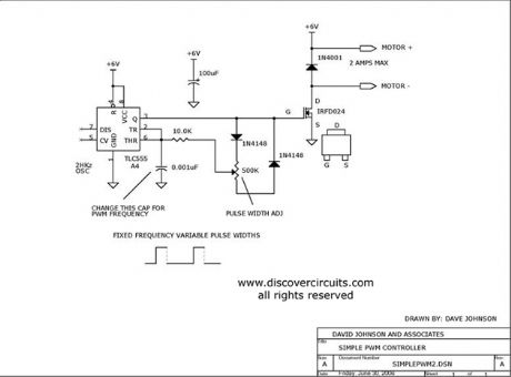
Using a CMOS version of the 555 timer, this circuit can be used to control the speed of a motor by adjusting the duty cycle of the pulses sent to the motor.
Source: discovercircuits
(View)
View full Circuit Diagram | Comments | Reading(4)
Ultra Low Power 32KHz Crystal Oscillator
Published:2012/9/5 20:34:00 Author:Ecco | Keyword: Ultra Low Power, 32KHz, Crystal Oscillator
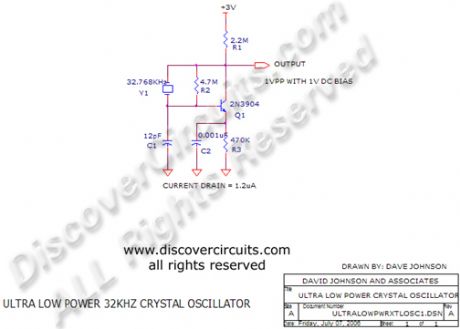
I have used this circuit many times when I needed a low frequency reference, which did not draw much power. With the components show, the current from a 3v battery is less than 1.2 microamps
Source: discovercircuits
(View)
View full Circuit Diagram | Comments | Reading(1687)
XENON LAMP FLASH DETECTOR
Published:2012/9/5 20:33:00 Author:Ecco | Keyword: XENON LAMP FLASH, DETECTOR
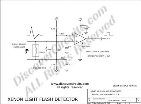
This circuit uses a small 2.5mm square photo diode in conjunction with a 100mH coil to detect the short light flashes from a xenon lamp. The coil makes the circuit immune to normal room lights. Its 10mv sensitivity can detect light flashes from a range of over 100 feet. Reflections from a room?s walls and ceiling is usually enough to trigger the circuit. The entire circuit draws only 3 Microamps from a 6 to 9 volt battery.
Source: discovercircuits (View)
View full Circuit Diagram | Comments | Reading(9)
WIDE BAND ZERO CROSS DETECTOR
Published:2012/9/5 20:22:00 Author:Ecco | Keyword: WIDE BAND, ZERO CROSS, DETECTOR
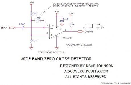
This circuit was designed to convert a low amplitude 40KHz signal into a clean square wave signal. It will work with inputs as small as 5mv peak-to-peak or as large as 3 volts peak to peak. The input frequency can range from a few kilohertz to about 150KHz.
Source: discovercircuits (View)
View full Circuit Diagram | Comments | Reading(0)
PRECISION AC PEAK DETECTOR
Published:2012/9/5 20:22:00 Author:Ecco | Keyword: PRECISION , AC PEAK , DETECTOR
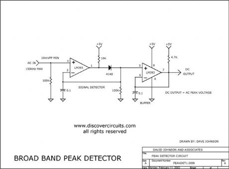
This unique circuit uses a very inexpensive voltage comparator to form a peak detector. The DC voltage produced tracks the positive peak of the input signal. It works from about ten millivolts to about 10 volts peak to peak. The maximum frequency is about 150KHz.
Source: discovercircuits (View)
View full Circuit Diagram | Comments | Reading(7)
DC Current Indicator 6
Published:2012/9/5 20:20:00 Author:Ecco | Keyword: DC Current, Indicator
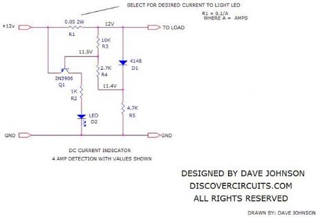
The circuit below is a simple way to indicate when DC current is flowing through a wire. The circuit is designed so it will turn on a LED indicator light, whenever the voltage drop across a shunt resistor exceeds about 0.1 volts. The value of the resistor can be selected based on the desired current flow. Although I show a circuit for 12v operation, the circuit can be used over a wide range from 3v to perhaps 24v.
Source: discovercircuits (View)
View full Circuit Diagram | Comments | Reading(2904)
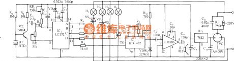
Three-way flashing light string circuit (3 )
Published:2012/9/4 22:47:00 Author:Ecco | Keyword: Three-way , flashing light string
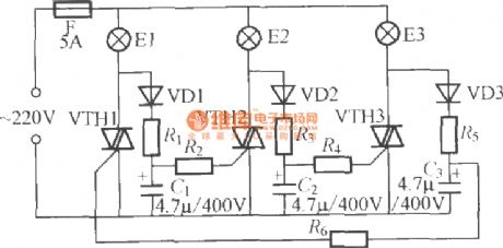
As shown in figure, it uses three-way flashing light string controller with three ordinary TRIACs, and it can make light string be lit in a cycle, the maximum output power of each road is up to 1000W, and the circuit is simple and easy to produce. VTH1 ~ VTH3 use 5A, 600V TRIAC, the maximum load power is up to 1000W ; VD1~VD3 can use 1N4007 ordinary silicon rectifier diodes.
(View)
View full Circuit Diagram | Comments | Reading(1590)
Pyroelectric infrared sensor automatic lamp circuit (5)
Published:2012/9/4 22:45:00 Author:Ecco | Keyword: Pyroelectric, infrared sensor , automatic lamp
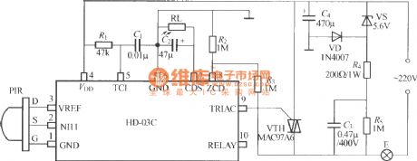
As shown in the figure, it is pyroelectric infrared sensor automatic light with dedicated module, so the circuit is very simple. HD-03C is the pyroelectric infrared -specific module produced by Xianju Yongling electronics factory in Zhejiang, it contains all pyroelectric infrared processing circuits, and it can work as it is connected with a pyroelectric infrared sensor PIR.
(View)
View full Circuit Diagram | Comments | Reading(2080)
Double-key touching lamp switch circuit (3)
Published:2012/9/4 22:41:00 Author:Ecco | Keyword: Double-key , touching lamp switch

As shown in the figure, it is a double-key touching lamp switch with Darlington transistor, the feature of circuit is that touching tablet and 220V AC mains are isolated by power transformer T, it is relatively safer. The T can be 220V/9V, 5VA small power transformer; K should use ultra - small JZC-22F/2Z-09 power relay.
(View)
View full Circuit Diagram | Comments | Reading(1197)
Double-key touching lamp switch circuit (6)
Published:2012/9/4 22:38:00 Author:Ecco | Keyword: Double-key, touching lamp switch
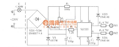
As shown in the figure, it is a double-key touching lamp switch with unique design, and the left part of dashed in the figure is the general lighting circuit, the right part is the light switch. It only has two leading-out terminals to external, so it can easily replace ordinary mechanical switch without changing indoors original wiring, this access method is called two-wire system connection. The load capacity of the circuit is limited by the regulator VS, so the bulb E's power should not be greater than 40W.
(View)
View full Circuit Diagram | Comments | Reading(1044)
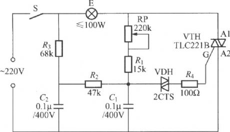
Double-key touching lamp switch circuit (7)
Published:2012/9/4 22:34:00 Author:Ecco | Keyword: Double-key, touching lamp switch

As shown in the figure, it is a double-key touching lamp switch with two-wire system connection, and the left part of dashed in the figure is the general lighting circuit, the right part is the light switch, M1 is the touching tablet to turn on the light, M2 is the touching tablet to turn off the light. The load capacity of the circuit is mainly determined by the current capacity of VT3 and VD1 ~ VD4, the icon data load power is below 100W, and the load is suitable for incandescent bulbs, and the inductive load can not be used.
(View)
View full Circuit Diagram | Comments | Reading(1250)
TRIAC dimmer light circuit with dual time constant
Published:2012/9/4 22:19:00 Author:Ecco | Keyword: TRIAC , dimmer light , dual time constant
In order to solve the lag and light transition phenomena, it can use the Triac dimming light circuit shown in the figure with dual time constant. The circuit increases R3 , C2 resistor-capacitor network, and the reducing charge on capacitor C1 can get promptly complement through C2, R2, R3 circuit, it can effectively reduce the lag and lighting transitions and also expand minimum brightness adjustment range of light.
(View)
View full Circuit Diagram | Comments | Reading(4464)
Sonic remote control light switch circuit (1 )
Published:2012/9/4 22:08:00 Author:Ecco | Keyword: Sonic , remote control, light switch
It uses clap as a remote command, once pat your palms, the lights will be lit; pat your palms again, the lights will be extinguished. The inverter I ~ IV uses a piece of six NOT gate CD4096 digital integrated circuit; B uses FT- 27, HTD27A -1 ordinary piezoelectric ceramic.
(View)
View full Circuit Diagram | Comments | Reading(3789)
Sonic remote control light switch circuit (2)
Published:2012/9/4 22:11:00 Author:Ecco | Keyword: Sonic , remote control , light switch
As shown in figure, it is a sonic remote control light switch with SK-Ⅳ voice-control ASIC, it has strong anti-interference ability, reliable performance. K uses small electromagnetic relay with 6V operating voltage, such as JZC -22F, DC6V ; B is available to use CRZ2-113F electret condenser microphone.
(View)
View full Circuit Diagram | Comments | Reading(4104)
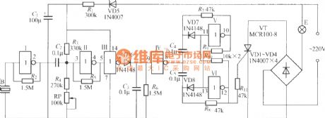
Voice-control music synchronized with lantern water controller circuit
Published:2012/9/4 22:03:00 Author:Ecco | Keyword: Voice-control , music synchronized , lantern water, controller
As shown in the figure, the circuit consists of voice circuit, four-phase pulse distributor/ driver, SCR trigger control circuit, music circuit and AC buck rectifier circuit. After the burst sound signal starts lantern, the music will play, Subsequently, the lantern will flow like water or chase with the melody and loudness size, and the music and audio loudness are faster; Conversely, water flowing velocity is slower. The lanterns changes synchronized with the main theme of the song.
(View)
View full Circuit Diagram | Comments | Reading(887)
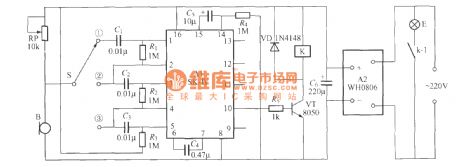
Voice-control double light switch circuit (SK-IV)
Published:2012/9/4 21:39:00 Author:Ecco | Keyword: Voice-control , double light switch

The circuit uses SK-IV voice-control integrated circuit as the core component. Since the manifold requires three times of sound emitted by user continuously at a specific time to trigger the work, the circuit has a very high anti - interference performance. VS can use the 6V, 1/2W Zener diode; VTH1 , VTH2 should use 1A/400V small plastic Triac with small trigger current, such as MAC94A4 with control load being up to 100W; T is 220V/9V, 5VA small-quality power transformer. Other components have no special requirements.
(View)
View full Circuit Diagram | Comments | Reading(1939)
Battery Charge Current Indicator
Published:2012/9/4 20:56:00 Author:Ecco | Keyword: Battery Charge, Current Indicator
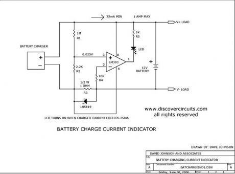
This circuit turns on a LED whenever it detects at least 25ma of battery charge current.
Source: discovercircuits (View)
View full Circuit Diagram | Comments | Reading(3885)
Acceptable Voltage Indicator
Published:2012/9/4 20:55:00 Author:Ecco | Keyword: Acceptable , Voltage Indicator
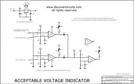
I have used this circuit many times in custom test fixtures where a simple go-no go indication was needed. The circuit can also be used to adjust a particular voltage be within specific high or low limits. The three LEDs will indicate if the voltage is high, low or OK. When connected to other converters, such as a frequency to voltage converter, a current to voltage converter or a power to voltage meter, it could provide a quick indication of a proper level.
Source: discovercircuits (View)
View full Circuit Diagram | Comments | Reading(1067)
VERY LOW POWER GATED CRYSTAL OSCILLATOR
Published:2012/9/4 20:55:00 Author:Ecco | Keyword: VERY LOW , POWER GATED , CRYSTAL OSCILLATOR
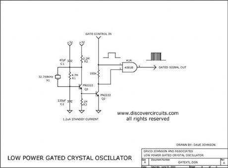
The circuit gates the output of a continuously operating 32KHz crystal oscillator to the input of a C-MOS buffer when clock pulses are needed. The technique gets around the problem of a slow starting crystal oscillator by keeping the oscillator going and switching on a transistor power stage only as needed. The method keeps the standby power consumption to a very low 1uA when used with a 3v supply.
Source: discovercircuits (View)
View full Circuit Diagram | Comments | Reading(3206)
Low Value Capacitance Meter
Published:2012/9/4 20:54:00 Author:Ecco | Keyword: Low Value, Capacitance Meter
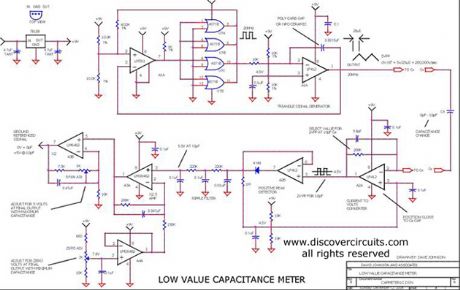
This circuit was originally designed to measure the volume of fluid inside a medical syringe. As designed, it produces a zero to 5 volt output, corresponding to a capacitance change of about 10 picofarads. With a digital voltmeter, at its output, it can resolve a capacitance change of 0.002 picofarads or 2 femtofarads.
Source: discovercircuits (View)
View full Circuit Diagram | Comments | Reading(3759)
| Pages:352/2234 At 20341342343344345346347348349350351352353354355356357358359360Under 20 |
Circuit Categories
power supply circuit
Amplifier Circuit
Basic Circuit
LED and Light Circuit
Sensor Circuit
Signal Processing
Electrical Equipment Circuit
Control Circuit
Remote Control Circuit
A/D-D/A Converter Circuit
Audio Circuit
Measuring and Test Circuit
Communication Circuit
Computer-Related Circuit
555 Circuit
Automotive Circuit
Repairing Circuit