
Circuit Diagram
Index 349
Incandescent Lamp Inrush Current Limiter
Published:2012/9/6 20:34:00 Author:Ecco | Keyword: Incandescent Lamp, Inrush Current Limiter
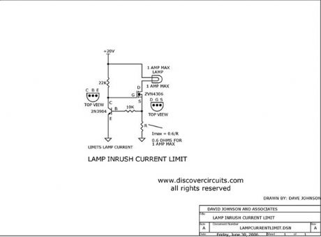
This circuit limits the large inrush current often associated with large incandescent lamps. With the components shown the current is limited to 1 amp, but it could be scaled to any desired current.
Source: discovercircuits (View)
View full Circuit Diagram | Comments | Reading(4860)
40KHz TV-VCR LIGHT SOURCE REPEATER
Published:2012/9/6 20:26:00 Author:Ecco | Keyword: 40KHz , TV-VCR, LIGHT SOURCE REPEATER
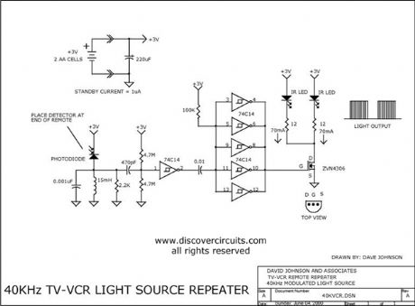
This circuit is designed to be placed directly in front of a standard TV or VCR remote. The exiting light pulses produced by the circuit match the pulses from the remote but are about 10 times more powerful. Using the device, the remote can operate a TV or VCR over three times the normal distance.
Source: discovercircuits (View)
View full Circuit Diagram | Comments | Reading(2)
AC Current Controls Hour Meter -- February 13, 2010
Published:2012/9/6 20:26:00 Author:Ecco | Keyword: AC Current, Controls, Hour Meter

Many systems require routine maintenance based on machine operation time. The circuit below is a simple way to turn on a hour meter whenever AC power is supplied to the machine. An inexpensive snap-on current transformer from Magnetics Inc, is used to detect the AC current.
Source: discovercircuits (View)
View full Circuit Diagram | Comments | Reading(2035)
SIMPLE NITROGEN SPARK GENERATOR
Published:2012/9/6 20:26:00 Author:Ecco | Keyword: SIMPLE, NITROGEN SPARK GENERATOR
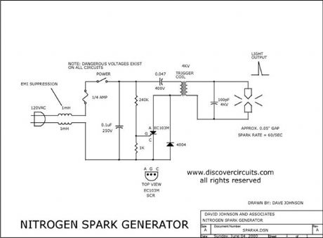
Nitrogen or air sparks are very powerful light sources that produce flashes that last only a few nanoseconds. This line-powered circuit generates a continuous series of very small sparks across electrodes with a 0.05-inch gap.
Source: discovercircuits (View)
View full Circuit Diagram | Comments | Reading(4519)
Low Voltage H-bridge
Published:2012/9/6 20:23:00 Author:Ecco | Keyword: Low Voltage, H-bridge
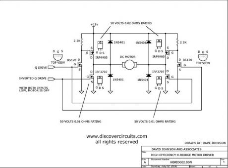
TTL type Q and inverted Q inputs control a classic H-bridge circuit, rated at 50 volts and about 10 amps. The circuit can control power and direction of a DC motor.
Source: discovercircuits (View)
View full Circuit Diagram | Comments | Reading(2546)
Home Made Geophone Detects Foot Stomp
Published:2012/9/6 20:23:00 Author:Ecco | Keyword: Home Made , Geophone , Detects, Foot Stomp
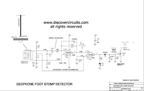
A home made geophone is made from a strong magnet, a coil of wire and a rubber band. The circuit is sensitive enough to detect the vibrations of a nearby foot stomp. It could be used as an earthquake detector.
Source: discovercircuits (View)
View full Circuit Diagram | Comments | Reading(7)
Wave Power Generator Demo System
Published:2012/9/6 20:23:00 Author:Ecco | Keyword: Wave Power Generator, Demo System
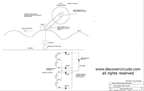
An inexpensive stepper motor is used as a voltage generator in this wave generator demo.
Source: discovercircuits (View)
View full Circuit Diagram | Comments | Reading(0)
Electrical Device Harvests Earthworms
Published:2012/9/6 20:22:00 Author:Ecco | Keyword: Electrical Device, Harvests Earthworms
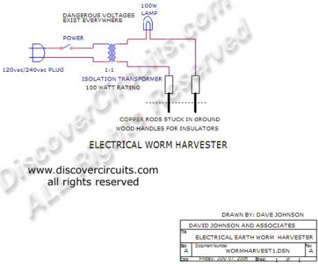
A 120vac or 240vac isolation transformer is used to force earthworms from the ground.
Source: discovercircuits (View)
View full Circuit Diagram | Comments | Reading(805)
40KHz Light Detector with High Ambient Light Immunity
Published:2012/9/6 20:21:00 Author:Ecco | Keyword: 40KHz , Light Detector , High Ambient, Light Immunity
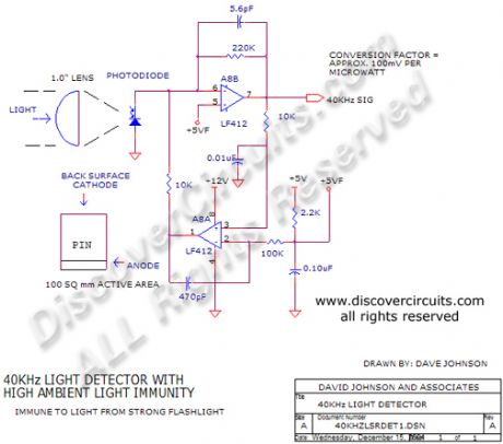
This circuit is designed for detecting infrared light modulated at around 40KHz. Its feedback scheme cancels much of the DC component from ambient light. It?s conversion factor is about 100 millivolts per microwatt of 900nm light.
Source: discovercircuits (View)
View full Circuit Diagram | Comments | Reading(0)
High Impedance JFET Buffers
Published:2012/9/6 20:14:00 Author:Ecco | Keyword: High Impedance, JFET Buffers
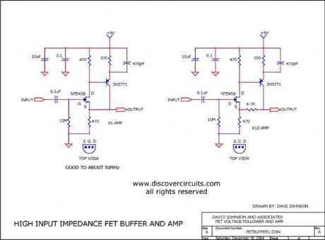
I have used these circuits many times. They are great when you need a low gain AC signal amplifier with a very high input impedance. It is good to beyond 50MHz. (View)
View full Circuit Diagram | Comments | Reading(2743)
Charge Coupled MOSFET Relay
Published:2012/9/6 20:12:00 Author:Ecco | Keyword: Charge Coupled , MOSFET Relay
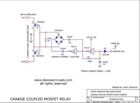
This circuit acts as an AC/DC relay with a rating up to 50 volts peak and up to 10 amps of current. The differential oscillator supplies voltage to the gates of the two FETs with good isolation will drawing only 1.5ma of current.
Source: discovercircuits (View)
View full Circuit Diagram | Comments | Reading(1208)
Door Knock Beeper -- June 14, 2009
Published:2012/9/6 20:12:00 Author:Ecco | Keyword: Door Knock , Beeper
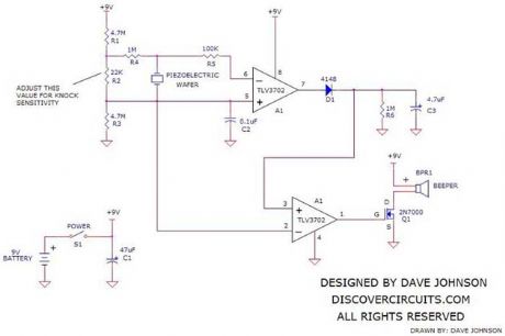
In some apartment buildings and homes, not equipped with a door bell, it may be hard to hear someone knocking on the front door. The circuit below provides a means to activate a loud beeping sound inside, whenever someone knocks on the door from the outside. The circuit is powered by a 9v battery, which should provide years of service. An on/off switch allows the device to be turned off if desired. It is suggested that the circuit be housed in a plastic box with a 9v battery holder. A Serpac box from Mouser, part number 635-211-I-G is just right for this application. It is about 4 inches long and 2.6 inches wide. It has a nice compartment for a 9v battery.
Source: discovercircuits (View)
View full Circuit Diagram | Comments | Reading(1463)
Ramping LED Driver
Published:2012/9/6 20:10:00 Author:Ecco | Keyword: Ramping, LED Driver
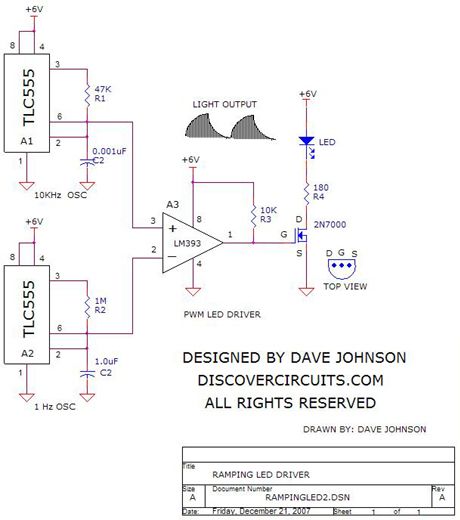
The circuit below was designed to drive a LED with an intensity ramping mode. Two 555 timers generate two different triangle waveforms. The upper device generates a 10KHz signal while the lower unit produces a 1Hz signal. The two signals are fed to a voltage comparator. The result is a pulse width modulation (PWM) signal, which with the aid of the FET, drives the LED in such a way that its average light output slowly ramps from about zero light to maximum and then slowly dims back down. The circuit should operate over a supply voltage ranging from 3v to 12v. You can easily vary the ramping time by changing the value of the 1M resistor. For an interesting effect, you can place a 1N4148 diode in parallel with the 1M resistor, with the cathode (banded end) side connected to pin 3.
Source: discovercircuits (View)
View full Circuit Diagram | Comments | Reading(1477)
Pot Controlled Variable LED Intensity Circuit -- September 24, 2009
Published:2012/9/6 20:09:00 Author:Ecco | Keyword: Pot Controlled, Variable LED Intensity
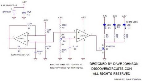
The circuit below uses power from four rechargeable AA NiMH cells to drive 3 white LEDs. A potentiometer varies the duty cycle of a pulse width modulator circuit to vary the intensity of the LEDs from 0% to 100%. The beauty of the circuit is that when the pot is all the way toward 0%, very little power is drawn from the battery. Likewise, when the pot slider is moved toward the 100% end, full power is fed to the LEDs. In effect, the pot becomes the on/off switch.
Source: discovercircuits (View)
View full Circuit Diagram | Comments | Reading(1154)
Medium Power 40KHz Ultrasound Transducer Driver
Published:2012/9/6 20:09:00 Author:Ecco | Keyword: Medium Power, 40KHz , Ultrasound Transducer Driver
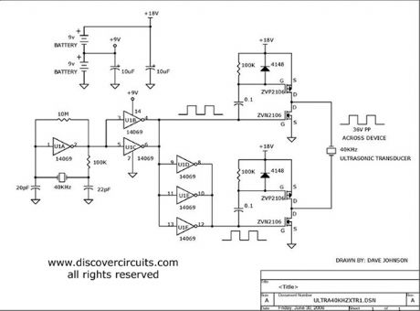
This crystal controlled circuit drives a 40KHz piezoelectric transducer with a 30v peak to peak signal.
Source: discovercircuits (View)
View full Circuit Diagram | Comments | Reading(4753)
Computer Controlled 100ma Current Source (July 11, 2008)
Published:2012/9/6 20:06:00 Author:Ecco | Keyword: Computer Controlled , 100ma , Current Source
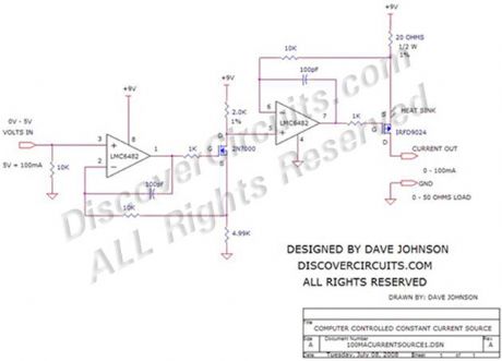
Often in industrial control systems a constant current source is needed, which is controlled by a computer and referenced to circuit ground. The circuit below converts a zero to 5v signal from a computer?s analog output into a current, with a full scale of 100ma. The circuit shown requires a 9v DC supply but any voltage from 9v to 12v will work.
Source: discovercircuits (View)
View full Circuit Diagram | Comments | Reading(0)
Electrical Current Indicator
Published:2012/9/6 20:04:00 Author:Ecco | Keyword: Electrical Current , Indicator
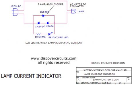
I designed this circuit as a simple current indicator for any load ranging from 40 watts to 250 watts. The circuit turns on a small LED, whenever it detects current flowing to a remote load.
Source: discovercircuits (View)
View full Circuit Diagram | Comments | Reading(903)
Battery Charge Current Indicator
Published:2012/9/6 20:01:00 Author:Ecco | Keyword: Battery Charge , Current Indicator
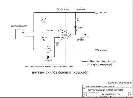
This circuit turns on a LED whenever it detects at least 25ma of battery charge current.
Source: discovercircuits (View)
View full Circuit Diagram | Comments | Reading(0)
Low Value Capacitance Meter
Published:2012/9/6 20:01:00 Author:Ecco | Keyword: Low Value, Capacitance Meter
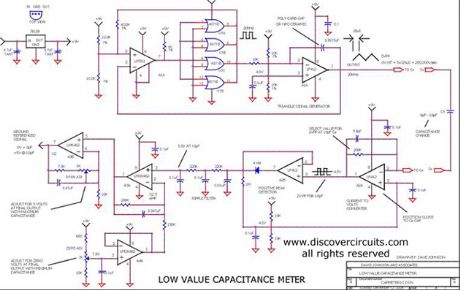
This circuit was originally designed to measure the volume of fluid inside a medical syringe. As designed, it produces a zero to 5 volt output, corresponding to a capacitance change of about 10 picofarads. With a digital voltmeter, at its output, it can resolve a capacitance change of 0.002 picofarads or 2 femtofarads.
Source: discovercircuits (View)
View full Circuit Diagram | Comments | Reading(0)
555 Timer Forms Simple PWM Motor Controller
Published:2012/9/6 20:00:00 Author:Ecco | Keyword: 555 Timer , Simple , PWM Motor Controller
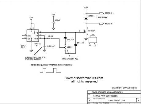
Using a CMOS version of the 555 timer, this circuit can be used to control the speed of a motor by adjusting the duty cycle of the pulses sent to the motor.
Source: discovercircuits (View)
View full Circuit Diagram | Comments | Reading(3399)
| Pages:349/2234 At 20341342343344345346347348349350351352353354355356357358359360Under 20 |
Circuit Categories
power supply circuit
Amplifier Circuit
Basic Circuit
LED and Light Circuit
Sensor Circuit
Signal Processing
Electrical Equipment Circuit
Control Circuit
Remote Control Circuit
A/D-D/A Converter Circuit
Audio Circuit
Measuring and Test Circuit
Communication Circuit
Computer-Related Circuit
555 Circuit
Automotive Circuit
Repairing Circuit