
Circuit Diagram
Index 342
Chime Circuit with 4049
Published:2012/9/11 20:20:00 Author:Ecco | Keyword: Chime
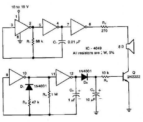
Resistor R1, capacitor C1, and two converters form a square wave generator, which produces the basic tone. The generator is sui followed by an inverter which serves as both a buffer and a driver for the President. The resistor R2, which has a minimum value of 100 ohms, limits the power and volume controls. The diode D1, capacitor C2, resistors R3 and R4, and two in converters to create the pulse generator which determines the power-up and decay times of the ring. (View)
View full Circuit Diagram | Comments | Reading(2256)
Microphone preamplifier with TLC251
Published:2012/9/11 20:19:00 Author:Ecco | Keyword: Microphone, preamplifier
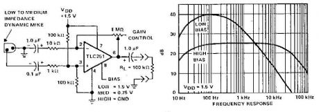
A microphone preamplifier using: om CMOS op amp with its own battery, is small enough to be placed in a case of small microphone. The amplifier operates from a 1.5V battery cathode mercury low supply currents. This preamp will operate at very low power and maintain a reasonable frequency response as well. The TLC251 is operating in low bias (operating at 1.5 V) draws a supply current of only 10 and has a year - frequency response of 3 dB 27 Hz to 4.8 kHz. With 8-pin grounded, which is designated as the polarization state high limit increases above 25 kHz. Supply current is only - 30 pA under these conditions. (View)
View full Circuit Diagram | Comments | Reading(0)
Automatic audio fader circuit
Published:2012/9/11 20:18:00 Author:Ecco | Keyword: Automatic, audio fader
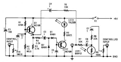
The automatic fader drops at the background music while the narration is in place. The control input through RIO, a preset audio level control, into an emitter-follower buffer stage CQI). The buffer provides high input impedance and ensures that the source impedance is low enough to drive the rectifier and smoothing circuit, consisting of DI, D2, and C5. The smoothed output drives a simple LED circuit. LD and R8 form an IR input pad through which the output is fed through C6 and C7 to the output jack. .. (View)
View full Circuit Diagram | Comments | Reading(0)
High input impedance amplifier CA3440
Published:2012/9/11 20:17:00 Author:Ecco | Keyword: High input, impedance amplifier
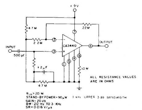
This circuit takes advantage of the leakage of low power, high input impedance, frequency and capacity of the excellent CA3440. Only one input coupling capacitor of 500 pF is needed to achieve a 20 Hz, -3 dB low frequency response. .. (View)
View full Circuit Diagram | Comments | Reading(900)
Pincushion correction circuit -2
Published:2012/9/10 22:59:00 Author:Ecco | Keyword: Pincushion correction
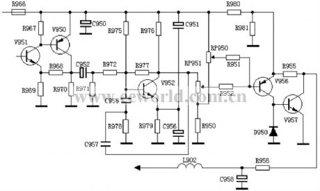
This circuit is part of the Venus D2918 model pincushion correction circuit, and compared to the pincushion correction circuit -1, it also has V951 , V950 two-stage amplifier, the reason is that field sawtooth is not taken from the field deflection coil sampling resistor, but from TDA8838 ( 46) feet, due to its lesser amplitude, it adds the two-stage amplifier.
(View)
View full Circuit Diagram | Comments | Reading(1121)
Current limiting audio amplifier circuit
Published:2012/9/11 1:38:00 Author:Ecco | Keyword: Current limiting , audio amplifier
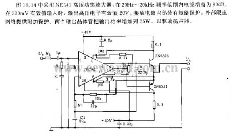
The circuit shown in Figure 18.44 uses NE541 high voltage power amplifier, and its current gain is 90dB at the frequency range of 20Hz ~ 20kHz; when it has 300mV rms input, output high voltage level RMS is 20V. The internal IC is equipped with short-circuit protection. The external current limiting network provides the additional protection. The two output transistors can increase the output power to 75W to drive the speaker.
(View)
View full Circuit Diagram | Comments | Reading(1747)
Temperature sensor transmitter circuit
Published:2012/9/11 1:30:00 Author:Ecco | Keyword: Temperature sensor, transmitter
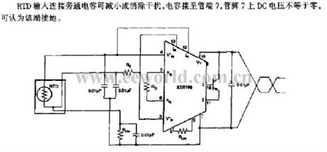
RTD input is connected to bypass capacitor to reduce or eliminate the interference. When the capacitor is connected to pin 7 of pipe, the DC voltage on pin 7 is not equal to zero, that means the pin 7 is grounded.
(View)
View full Circuit Diagram | Comments | Reading(1373)
Temperature sensor interface circuit
Published:2012/9/11 1:23:00 Author:Ecco | Keyword: Temperature sensor, interface
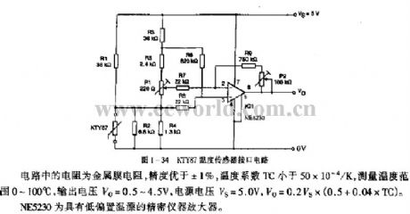
The resistor in circuit uses a metal film resistor, and its precision is better than ± 1 %, temperature coefficient TC is less than 50 × 10-4 / K, measurement temperature range is between 0~ 100 ℃, output voltage Vo = 0.5 ~ 4.5V, supply voltage VS = 5.0 V, Vo = 0.2VS × (0.5 +0.04 × TC). NE5230 is a low bias temperature precision instrument amplifier.
(View)
View full Circuit Diagram | Comments | Reading(1840)
The threshold switching circuit with TCAl05/TcA205A
Published:2012/9/11 1:45:00 Author:Ecco | Keyword: threshold switching
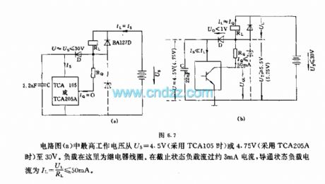
The maximum operating voltage in the circuit (a) changes from the US = 4.5V ( TCA105) 4.75V ( TCA205A) to 30V. The load here is relay coil. The current flowing load is about 3mA current in the turn-off state and IL = UL / RL ≤ 50mA in the turn-on state.
(View)
View full Circuit Diagram | Comments | Reading(1782)
The photoelectric control trigger circuit
Published:2012/9/11 1:50:00 Author:Ecco | Keyword: photoelectric control , trigger
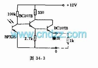
The circuit plays the raster control role of the relay switch. When the light is dimmed, the current output by phototransistor is about 8mA ( supply voltage is 8V ). When the illumination is over 50lx, the circuit flips, the output is 0. The limiting frequecncy of the circuit is 6kHz.
(View)
View full Circuit Diagram | Comments | Reading(956)
The lathe no-load automatically shut-down and power - saving circuit 1
Published:2012/9/10 22:52:00 Author:Ecco | Keyword: lathe , no-load, automatically shut-down, power - saving
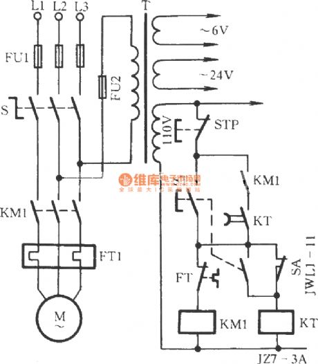
When the lathe workers operate lathe, the spindle needs to stop rotating, they are accustomed to placing operating lever in the parking position, then they will leave the lathe do other things and ignore to press the stop button, that will waste of energy because of the motor no-load operation for a long time. The circuit shown as the figure can avoide motor from idling.
(View)
View full Circuit Diagram | Comments | Reading(1602)
Single-phase motor impedance with indicator light speed adjusting circuit
Published:2012/9/10 22:45:00 Author:Ecco | Keyword: Single-phase motor, impedance , indicator light, speed adjusting
Asshown in Figure, the circuituses reactor tap to connect withindicator H. When the motor is operating, the two taps of reactor pass current to generate voltage, then the indicator H is lit.
(View)
View full Circuit Diagram | Comments | Reading(1270)
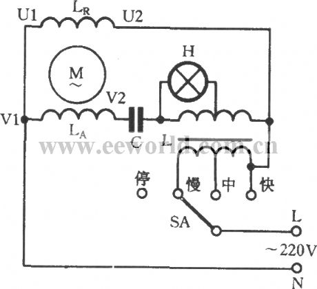
Single-phase motor reactor tap speed adjusting circuit
Published:2012/9/10 22:38:00 Author:Ecco | Keyword: Single-phase motor, reactor tap, speed adjusting
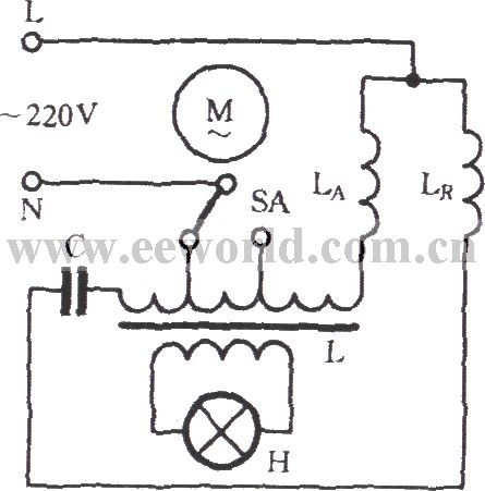
The different speed blocks of reactor L are adjusted by tap and the speed switch. L is connected to the secondary winding LA in series. LR is the primary winding. L provides supply voltage through another winding for indicator H.
(View)
View full Circuit Diagram | Comments | Reading(1147)
Single phase motor electronic stepless thyristor circuit
Published:2012/9/10 22:29:00 Author:Ecco | Keyword: Single phase , motor , electronic , stepless, thyristor
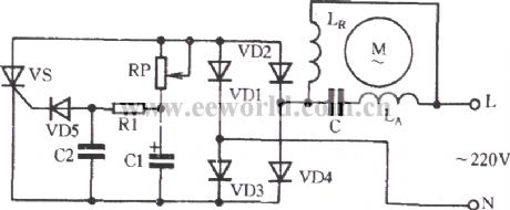
As shown in Figure, adjusting potentiometer RP can adjust the conduction angle of thyristor, and the output voltage is changed, so as to achieve the purpose of stepless speed adjusting of motor. RP resistance is low,and VS has high breakover angle, high output voltage, then motor has high speed; conversely, the high RP resistance makes low speed of the motor.
(View)
View full Circuit Diagram | Comments | Reading(2216)
Passive subwoofer filter
Published:2012/9/10 21:50:00 Author:Ecco | Keyword: Passive , subwoofer filter
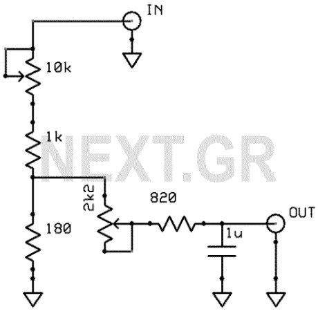
The schematic shown, does no need any power supply because is a simple low frequency passive filter. It could be usefull if you want to drive an extra subwoofer from your stereo system. (View)
View full Circuit Diagram | Comments | Reading(4905)
FM IF Subsystem with CA3189E
Published:2012/9/10 21:49:00 Author:Ecco | Keyword: FM IF Subsystem
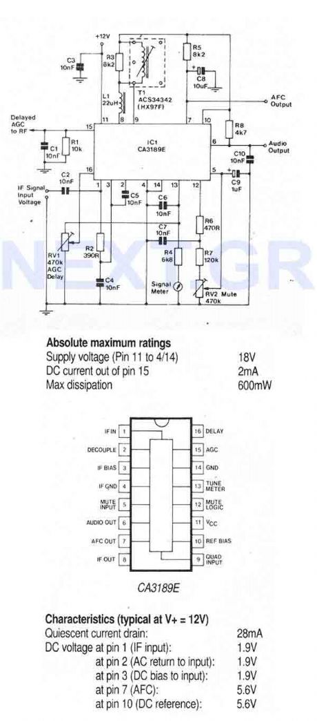
TheCA3189E is a comprehensive FM-IF system designed for high fidelity FM tuners. It includes a three stage FM-IF amplifier/limiter configuration with level detectors for each stage, a double-balanced quadrature FM detector and an audio amplifier that features the optional use of a muting circuit. The advanced circuit design includes desirable special features such as delayed AGC for the RF tuner, an AFC drive circuit, and an output signal to drive a tuning meter and/or provide stereo switching logic. In addition, internal power supply regulators maintain a nearly constant current drain over the voltage supply range of +8V to +16V. Distortion is primary a function of the phase linearity characteristics of the external detector coil. (View)
View full Circuit Diagram | Comments | Reading(1158)
Motion Alarm
Published:2012/9/10 21:42:00 Author:Ecco | Keyword: Motion Alarm
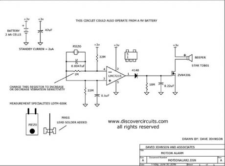
Using a piezoelectric device, this circuit will activate a beeper whenever the circuit is moved. It could be used as an earthquake alarm.
Source: discovercircuits (View)
View full Circuit Diagram | Comments | Reading(1471)
MSC1210 Reset Circuit
Published:2012/9/10 21:27:00 Author:Ecco | Keyword: Reset
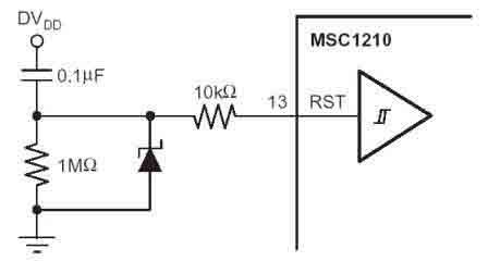
According to the MSC1210 datasheet, you will perform an external reset by taking RST pin high for two tOSC periods as this stops device operation, crystal oscillation, causes all digitall pins to be pulled high from that point and then followed by taking the RST pin low that initiates the reset procedure. (View)
View full Circuit Diagram | Comments | Reading(1070)
Digital Volume Control
Published:2012/9/10 21:26:00 Author:Ecco | Keyword: Digital Volume, Control
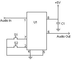
This digital volume control has no pot to wear out and introduces almost no noise in the circuit. Instead, the volume is controlled by pressing UP and DOWN buttons. This simple circuit would be a great touch to any home audio project. (View)
View full Circuit Diagram | Comments | Reading(0)
One transistor audio mixer (2N3563)
Published:2012/9/10 21:26:00 Author:Ecco | Keyword: One transistor , audio mixer
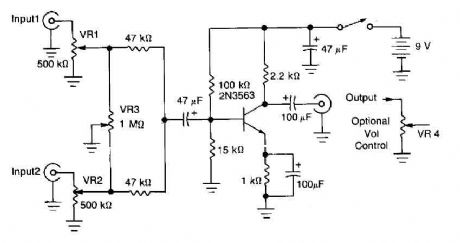
This circuit mixer has an internal amplification with 2N3563 transistor. The two input signals can be independently controlled by VRI and VR2. The VR3 balance control is used to remove a signal while the other melted. (View)
View full Circuit Diagram | Comments | Reading(6045)
| Pages:342/2234 At 20341342343344345346347348349350351352353354355356357358359360Under 20 |
Circuit Categories
power supply circuit
Amplifier Circuit
Basic Circuit
LED and Light Circuit
Sensor Circuit
Signal Processing
Electrical Equipment Circuit
Control Circuit
Remote Control Circuit
A/D-D/A Converter Circuit
Audio Circuit
Measuring and Test Circuit
Communication Circuit
Computer-Related Circuit
555 Circuit
Automotive Circuit
Repairing Circuit