
Circuit Diagram
Index 345
Xenon Lamp Flash Detector
Published:2012/9/10 20:52:00 Author:Ecco | Keyword: Xenon Lamp , Flash Detector
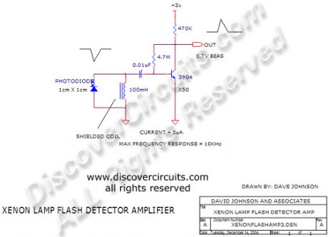
This circuit has a very low standby current requirement yet has very high sensitivity toward the light flashes from a xenon lamp. When connected to a flip/flop it can serve as an on on/off controller.
Source: discovercircuits (View)
View full Circuit Diagram | Comments | Reading(1997)
40KHz Ultrasound Receiver
Published:2012/9/10 20:46:00 Author:Ecco | Keyword: 40KHz , Ultrasound Receiver
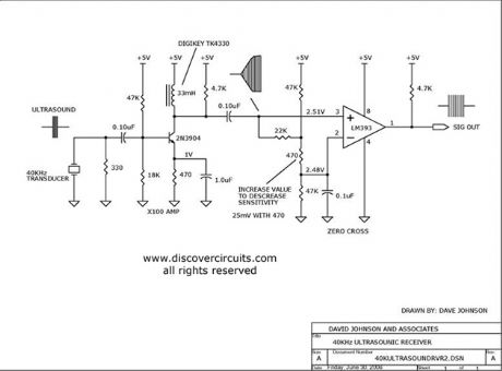
A X100 transistor amplifier is followed by a zero cross detector circuit, using a voltage comparator. The output is a TTL logic signal, corresponding to the received 40KHz signal.
Source: discovercircuits (View)
View full Circuit Diagram | Comments | Reading(2734)
Precision 40KHz Triangle Generator
Published:2012/9/10 20:44:00 Author:Ecco | Keyword: Precision , 40KHz, Triangle Generator
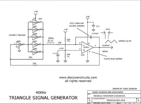
This circuit generates a precision 40KHz triangle waveform.
Source: discovercircuits (View)
View full Circuit Diagram | Comments | Reading(1791)
Brownout Voltage Tester
Published:2012/9/10 20:37:00 Author:Ecco | Keyword: Brownout, Voltage Tester

I used this circuit years ago to test AC line powered devices under 95vac line voltage conditions. It has a rating of 250 watts.
Source: discovercircuits (View)
View full Circuit Diagram | Comments | Reading(1009)
VIDEO SIGNAL EDGE ENHANCEMENTS
Published:2012/9/10 20:37:00 Author:Ecco | Keyword: VIDEO SIGNAL, EDGE ENHANCEMENTS
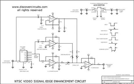
I designed this circuit many years ago, based on the claims that the technique would improve the quality of standard TV images. The circuit adds information to the edges of the objects and was reported to bring out more detail. After building and testing the circuit, I could definitely see a difference between it and a regular TV display but I don?t think most people would go to the trouble of installing the circuit for only a marginal improvement. Still, it is an interesting circuit with which someone might experiment.
Source: discovercircuits (View)
View full Circuit Diagram | Comments | Reading(721)
TV/VCR Infrared Remote Booster
Published:2012/9/10 20:37:00 Author:Ecco | Keyword: TV/VCR , Infrared , Remote Booster
This circuit will boost the signal from any infrared TV or VCR remote, extending the range by a factor of 3X.
Source: discovercircuits (View)
View full Circuit Diagram | Comments | Reading(4501)
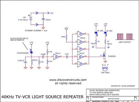
40KHz TV-VCR LIGHT SOURCE REPEATER
Published:2012/9/10 20:36:00 Author:Ecco | Keyword: 40KHz, TV-VCR, LIGHT SOURCE REPEATER
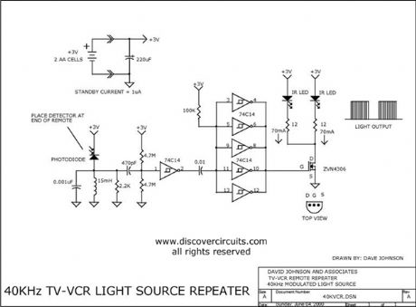
This circuit is designed to be placed directly in front of a standard TV or VCR remote. The exiting light pulses produced by the circuit match the pulses from the remote but are about 10 times more powerful. Using the device, the remote can operate a TV or VCR over three times the normal distance.
Source: discovercircuits (View)
View full Circuit Diagram | Comments | Reading(2333)
Audio Signal Detector Switch
Published:2012/9/10 20:26:00 Author:Ecco | Keyword: Audio Signal, Detector, Switch
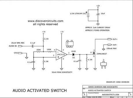
This circuit will activate a transistor switch when it detects at least 50mv peak to peak of an audio signal. It could be used to turn on a relay, routing the signal to were it is needed.
Source: discovercircuits (View)
View full Circuit Diagram | Comments | Reading(3058)
TEMPERATURE SENSOR WITH 4 TO 20mA CURRENT LOOP
Published:2012/9/10 20:24:00 Author:Ecco | Keyword: TEMPERATURE SENSOR , 4 TO 20mA , CURRENT LOOP
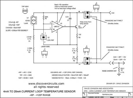
I designed a circuit similar to this one years ago to accurately measure the air temperature inside a building 1000s of feet from a control room. The circuit uses a very robust current loop method. It uses a highly accurate semiconductor temperature sensor and an equally accurate voltage reference. The circuit includes a diode bridge, so it is polarity independent. By using the component values indicated, the circuit should not require calibration. It has a range from ?40F to +120F and an accuracy of +/- one degree F.
Source: discovercircuits (View)
View full Circuit Diagram | Comments | Reading(2386)
ELECTRIC FIELD DISTURBANCE MONITOR - Alarm Discriminator + Battery Monitor
Published:2012/9/10 20:17:00 Author:Ecco | Keyword: ELECTRIC FIELD , DISTURBANCE MONITOR, Alarm Discriminator, Battery Monitor
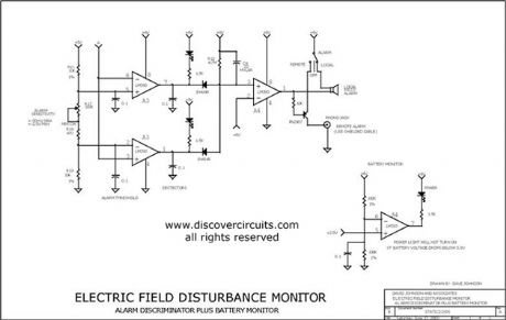
This schematic is the power supply and front-end sections of the field monitor that is discussed in more detail at Electric Field Disturbance Monitor. The system can detect human and animal motion by the electric fields they disturb.
Source: discovercircuits (View)
View full Circuit Diagram | Comments | Reading(2835)
Reduced Power Relay Driver Aug 3, 2008
Published:2012/9/10 20:13:00 Author:Ecco | Keyword: Reduced Power , Relay Driver
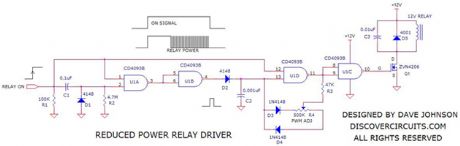
Relays can handle a lot of power. However, for certain power sensitive designs you would like to reduce the power needed to hold a relay closed. The circuit below performs such a task. It uses a single CD4093 quad NAND gate. When the ?on? logic input signal is detected, the relay is first pulsed on for about 500ms. This is sufficient time to insure the relay is fully closed. After that initial pulse the relay is then driven with a square wave signal, whose duty cycle can be adjusted. The signal duty cycle can be adjusted from about 10% to 90%. In most cases a 50% duty cycle will hold the relay closed. This reduces the average DC current required by the same factor, which means a 4:1 reduction in power. The circuit can operate over a wide 3v to 15v range.
Source: discovercircuits (View)
View full Circuit Diagram | Comments | Reading(763)
Anti - robbery alarm RCM1A/RCM1B transceiver module
Published:2012/9/10 1:03:00 Author:Ecco | Keyword: Anti - robbery , alarm , transceiver module
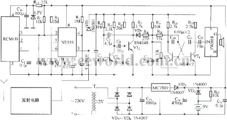
The circuit consists of two parts of a tiny radio transmitter and receiver control alarm. The transmitter is supplied by button battery, and it is compact and easy to carry. Once the accident happens, pressing the transmitter button, the receiver will send a very loud alarm sound. The transmitter circuit inlcudes transmitter module RCM1A, button batteries and launch button; wireless receiver alarm circuit is composed of receiver module RCM1B, monostable multivibrator, composite oscillator circuit, audio booster, high-loudness speaker, power supply circuit and other components.
(View)
View full Circuit Diagram | Comments | Reading(1277)
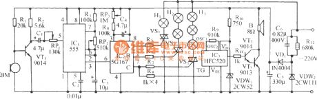
Voice control flowing Lantern circuit 5G167 with many famous songs
Published:2012/9/10 1:11:00 Author:Ecco | Keyword: Voice control, flowing Lantern , many famous songs
As shown in the diagram, the circuit consists of acoustic/electric sensor, audio amplifier, ring count pulse distribution/driver circuit, thyristor-controlled circuit, music sound circuit, audio amplifier circuit and AC buck rectifier circuit. IC1 uses 5G167 which is used for ring count pulse distribution/driver integrated circuit to rotate the Flash recorder box, it contains signal rectifier amplifier, voltage-controlled oscillator and 3-bit ring sequential counter and 3-drain output circuit and so on.
(View)
View full Circuit Diagram | Comments | Reading(1361)
Voice-control bi-directional flowing water lantern circuit with seashore (5G167)
Published:2012/9/10 1:20:00 Author:Ecco | Keyword: Voice-control, bi-directional , flowing water lantern , seashore
As shown in the diagram, the circuit consists of voice control circuit, monostable trigger, ring count pulse distribution circuit/drive circuit, thyristor trigger control circuit, wave sound audible circuit and AC buck rectifier circuit, it can make three-way Lantern strings auto reverse in both directions, accompanied by the waves beating the shore or the nature sound from mountain and stone.
(View)
View full Circuit Diagram | Comments | Reading(946)
Voice-control bi-directional flowing water color lantern with sea wave circuit
Published:2012/9/10 1:22:00 Author:Ecco | Keyword: Voice-control, bi-directional , flowing water, color lantern , sea wave

As shown in the diagram, the circuit consists of voice control circuit, monostable trigger, ring count pulse distribution circuit/drive circuit, thyristor trigger control circuit, sea wave sound audible circuit and AC buck rectifier circuit, it can make three-way Lantern strings auto reverse in both directions, accompanied by the nature sound from mountain and stone or waves beating the shore.
(View)
View full Circuit Diagram | Comments | Reading(1053)
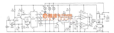
The triac liquid level control circuit
Published:2012/9/9 22:09:00 Author:Ecco | Keyword: triac , liquid level control
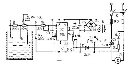
As shown in the figure, the controller is composed of the water level controller, trigger controller, and buck rectifier circuit.
The water level detecting electrodes a , b , c, and W1 , R1 , R2, and R3 form a bias circuit which can be used as a liquid level detector.
When the water surface is below b, VP -b ≈ R3 x VDD / ( RW1 + R1 + R2 + R3 ) < 1/3VDD, 555 is set, SCR is triggered and turned on, then the motor runs for pumping.
When the water level raises to a, Vp - a ≈ R3 x VDD / ( Rw1 ten R3 ) > 2/3VDD, then 555 resets, pin 3 is in low level. SCR is turned off, the motor stops because of no electricity, and then the circuit runs in the cycle to maintain the water level in a certain range.
(View)
View full Circuit Diagram | Comments | Reading(2075)
Three-phase motor △ low-speed operation circuit
Published:2012/9/10 1:31:00 Author:Ecco | Keyword: Three-phase motor , low-speed operation
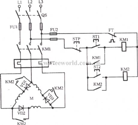
Sometimes the motor is required to run at low speed or without borrowing mechanical gearbox, the effect can be realized by the circuit shown as the figure. From the figure, three-phase windings are connected VD1~VD3 respectively, then people can press normally open contact KM2, ST1, then KM1l pulls in, VD1, VD2 VD3 are connected to winding, motor M start running at low speed. And then pressing ST2, KM2 pulls in, VD1, VD2 VD3 are shorted, M runs at full speed under rated voltage.
(View)
View full Circuit Diagram | Comments | Reading(2080)
Gated automatic lamp circuit ( 1)
Published:2012/9/9 22:41:00 Author:Ecco | Keyword: Gated , automatic lamp
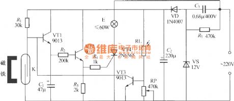
It is not convenience to find light switch when you return home at night. As shown in the figure, it is a gated automatic light, when you return home and open the door at night, the indoor lights will be turned on and turned off automatically after 50s, and it is blocked in the daytime and will not be illuminated. Gated automatic lighting circuit is shown as the figure, it consists of door and window sensor, delay circuit, light control circuit and power supply circuit. K can be used the JAG-4H dry reed pipe, small magnets should use small magnetic steel with strong magnetism.
(View)
View full Circuit Diagram | Comments | Reading(1453)
Four-color advertising light box with songs sound control circuit
Published:2012/9/9 22:47:00 Author:Ecco | Keyword: Four-color, advertising light box , songs sound control
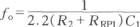
The circuit is shown as the figure. It is composed of time-base oscillator circuit, pulse count / distribution circuit, relay control circuit, songs sound circuit and AC buck rectifier circuit and other components. The circuit is used for advertisements, while it automatically transforms luminous color, it also issues a melodious music , it can not only beautify the night scene,but increaseadvertising effect . F1, F2, F3are the gate circuits ofa four- 2 NAND gate integrated circuit CD4011, where F1, F2 , and R1 , R2, and RP1, C1 form a multivibrator with oscillation frequency:
The oscillation period of the icon parameter is 44 ~ 92s, regulation RP1 can change its oscillation cycle TO.
(View)
View full Circuit Diagram | Comments | Reading(1132)
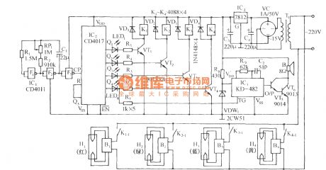
Four-way flashing light string circuit ( 2 )
Published:2012/9/9 22:52:00 Author:Ecco | Keyword: Four-way , flashing light string

As shown in the figure, it is four-way flashing light string controller with a four-way gradually dimming light-emitting diode driver integrated circuit. The HFC3484 Manifold produced by Wenzhou Fenghua Electronic Co., Ltd. is dedicated to four the lights slowly fading flashing chip for the light-emitting toys. VT5 ~ VT8 can use small plastic unidirectional thyristor MCR100-8 ( 1A/600V ); each group's power of Lanterns E1 ~ E4 can not exceed 100W. The relationship between HFC3484 Manifold's external resistor R and output cycle T is shown in the following table:
(View)
View full Circuit Diagram | Comments | Reading(2261)
| Pages:345/2234 At 20341342343344345346347348349350351352353354355356357358359360Under 20 |
Circuit Categories
power supply circuit
Amplifier Circuit
Basic Circuit
LED and Light Circuit
Sensor Circuit
Signal Processing
Electrical Equipment Circuit
Control Circuit
Remote Control Circuit
A/D-D/A Converter Circuit
Audio Circuit
Measuring and Test Circuit
Communication Circuit
Computer-Related Circuit
555 Circuit
Automotive Circuit
Repairing Circuit