
Circuit Diagram
Index 360
Pyroelectric infrared sensor automatic lamp circuit ( 8)
Published:2012/8/28 22:38:00 Author:Ecco | Keyword: Pyroelectric infrared , sensor, automatic lamp
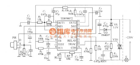
As shown in the figure, it is an infrared sensor automatically switch with TDH98072 ASIC, it uses two-wire connection to transformed the general lights into sensing automatically lamps, and the swicth can directly replace ordinary switch.
(View)
View full Circuit Diagram | Comments | Reading(1955)
Pyroelectric infrared sensor automatic lamp circuit (3)
Published:2012/8/28 22:55:00 Author:Ecco | Keyword: Pyroelectric infrared , sensor , automatic lamp
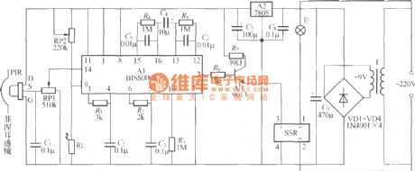
As shown in the figure, it is a sensing automatic lamp circuit using BISS0001 infrared sensing signal processing integrated circuit, the work is very stable and reliable, and it can be used in the bathroom, storage room, automatic lighting. PIR can use P228, PH5324, LH956 pyroelectric infrared sensors with installing Fresnel lens. SSR uses the JCX-2F-DC5V zero compact solid state relay, and it is compact and can be plugged and directly on the printed circuit board. Other components requirements are shown as the figure.
(View)
View full Circuit Diagram | Comments | Reading(5172)
Thyristor three - color dimming light circuit
Published:2012/8/28 22:12:00 Author:Ecco | Keyword: Thyristor , three - color, dimming light
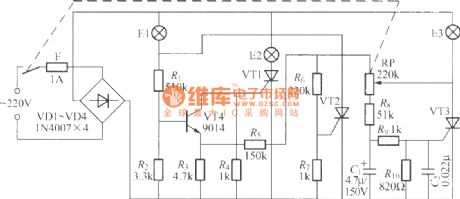
It only uses a potentiometer to control the on-off of red, green, blue three bulbs. VT1 ~ VT3 can use BT169D, 2N6565, MCR100 -8 small plastic one-way thyristor, E1 ~ E3 choose red, green, blue and other colored incandescent bulbs with power being lower than 60W accoring to personal favorites.
(View)
View full Circuit Diagram | Comments | Reading(2945)
Sensitive photorelay circuit
Published:2012/8/28 22:51:00 Author:Ecco | Keyword: Sensitive photorelay
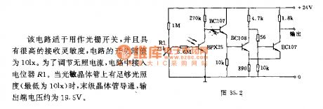
This circuit is adapted to be used as a grating switch with a high receiver sensitivity, the circuit switching threshold is 10Lx. In order to adjust the dark current, the circuit connects with potentiometer R1; when there is sufficient light intensity on phototransistor ( the lowest bit is 10Lx ), the last stage transistor turns on, the output voltage is about 19.5V.
(View)
View full Circuit Diagram | Comments | Reading(932)
Three - phase inverter bridge circuit
Published:2012/8/28 22:03:00 Author:Ecco | Keyword: Three - phase inverter bridge
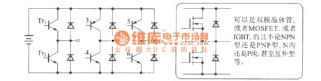
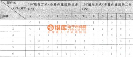
It can use a bipolar transistor, the model can be MOSFET, or IGBT, and regardless of the NPN-type or PNP type, N- channel or P-channel, and even complementary. Basic switching sequence of the three - phase inverter is shown as following (if the order is reversed, then the motor reverses. If it combines with the switch of DC converter, it also able to adjust the voltage)
(View)
View full Circuit Diagram | Comments | Reading(1264)
Three-speed regulating circuit with single-phase motor connected with capacitor in series
Published:2012/8/28 21:55:00 Author:Ecco | Keyword: Three-speed regulating , single-phase motor , capacitor , in series
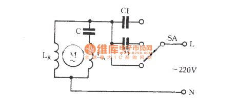
Some single-speed motors can use the methods shown in the figure to increase the capacitors C1, and C2. Then the motor is changed to a three-speed motor. C1, C2 must use paper dielectric capacitors or paper oil capacitors, and capacitance size is directly related to the speed of the motor.
(View)
View full Circuit Diagram | Comments | Reading(1436)
Two-speed regulating circuit with single-phase motor connected with capacitor in series
Published:2012/8/28 21:55:00 Author:Ecco | Keyword: speed regulating, single-phase motor , capacitor, in series
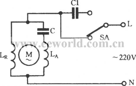
C1 must use paper capacitor or paper oil capacitor withvoltagebeingabove 400V, and it never uses a 400V electrolytic capacitor.
(View)
View full Circuit Diagram | Comments | Reading(2143)
Frequent commutation circuit of capacitor start single-phase motor
Published:2012/8/28 21:28:00 Author:Ecco | Keyword: Frequent commutation , capacitor start , single-phase motor
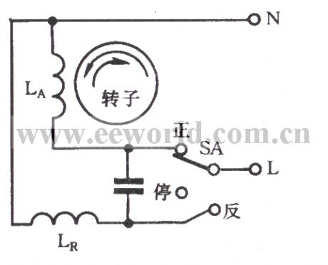
The motor is used for frequent operation commutation, and its turns of primary winding (running windings) LR and the secondary windings ( start winding ) LA, diameter, occupied slot number and distribution are the same, so commutation only needs to use a switch SA to change LR, LA power-on sequence. The circuit is shown as the chart.
(View)
View full Circuit Diagram | Comments | Reading(1441)
Capacitor start single-phase motor
Published:2012/8/28 21:19:00 Author:Ecco | Keyword: Capacitor start , single-phase motor
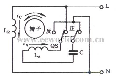
As shown in the figure, it is a reversing schematic. When the switch QS is in the positive position, the current iA of auxiliary winding LA is greater than current iA of the main winding LR, so that the the motor rotor rotates in positive direction. If the QS is set to the reverse position, the current iA direction of LA is changed 180o to make LR current iC be greater than LA current iA, the rotor rotates reversely.
(View)
View full Circuit Diagram | Comments | Reading(2942)
The speed control circuit of electric contact pressure gauge and inverter
Published:2012/8/28 21:38:00 Author:Ecco | Keyword: speed control , electric contact, pressure gauge, inverter
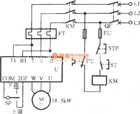
As shown in the figure, the circuit uses electric contact pressure gauge and inverter ( Japan Sanken 22kVA) to control the speed of on pump and realize water supply with constant pressure. The power supply terminal R , S , T of U can connect with switch, AC contactor. SP is installed in main road which is near the pump outlet with little effect from the amount of water.
(View)
View full Circuit Diagram | Comments | Reading(2461)
Two-button FET dimming light circuit
Published:2012/8/29 0:55:00 Author:Ecco | Keyword: Two-button, FET , dimming light
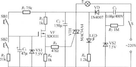
It uses two touching buttons switch fordimming, and one is used to highlight, the other is used to dim. Its advantagesinclude easy to use, beautiful appearance.
(View)
View full Circuit Diagram | Comments | Reading(1596)
Digital sound and light control stairs delay switch circuit ( 3 )
Published:2012/8/29 1:24:00 Author:Ecco | Keyword: Digital , sound and light control , stairs, delay switch
As shown in the figure, itis a simple sound, light control stairs and walkway delay lighting switchwith reliable performance,and ituses two-wiresystem to connect withpowerand light bulb. It also can directly replace ordinary light switches without changing the original lighting circuits.
(View)
View full Circuit Diagram | Comments | Reading(1538)
Digital sound and light control stairs delay switch circuit ( 4 )
Published:2012/8/29 1:26:00 Author:Ecco | Keyword: Digital, sound and light control, stairs, delay switch
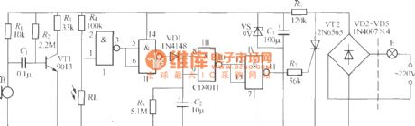
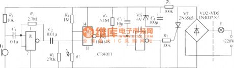
As shown in the figure, it is a sound and light control stairs delay switch circuit using CD4011 integrated circuit, and the circuit is relatively simple withgood performance. The circuit delay time is determined mainly by R5, C2 values, and the icon data is about 1min.
(View)
View full Circuit Diagram | Comments | Reading(1104)
Digital sound and light control stairs delay switch circuit ( 5 )
Published:2012/8/29 1:32:00 Author:Ecco | Keyword: Digital , sound and light control, stairs, delay switch
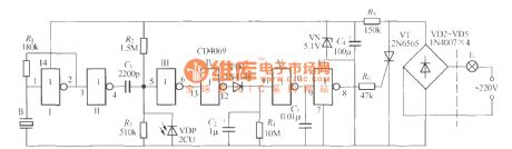
As shown in the figure, it is a sound and light control stairs delay switch circuit using CD4069 integrated circuit, and it uses the piezoelectric ceramicslice as the sound-electric transducer, the circuitis stable and reliable with good performance. The circuit delay time is set shorter with only15s around, and it is primarily decided by discharge time of R4 and C2. It can generally meet the using needs.
(View)
View full Circuit Diagram | Comments | Reading(1144)
Digital sound and light control stairs delay switch circuit ( 6 )
Published:2012/8/29 1:35:00 Author:Ecco | Keyword: Digital, sound and light control, stairs , delay switch
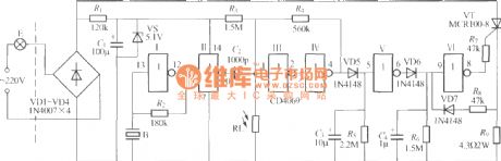
As shown in the figure, itis a sound and light control stairs delay switch circuitwithgood performance, the circuit has a high anti-interference performance, and a soft-start and over-current protection.
(View)
View full Circuit Diagram | Comments | Reading(993)
Automatic Headlight Brightness Switch
Published:2012/8/29 3:00:00 Author:Celina | Keyword: Automatic Headlight, Bipolar Output
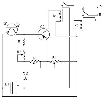
Driving the highway with your high-beam headlights can really increase your visibility, but can be a blinding hazard for other drivers. This simple circuit can be wired into your headlight switch to provide automatic switching between high and low beam headlights when there is oncoming traffic. It does this by sensing the lights of that traffic. In this way, you can drive safely with your high-beams on without blinding other drivers.
Notes
Q1 should me mounted in such a way so it points toward the front of the car with a clear line of site. Suitable places are on the dashboard, in the front grill, etc.
Adjust all the pots for proper response by testing on a deserted road.
S1 enables and disables the circuit.
B1 is, obviously, in the car already.
Before you try to connect this circuit, get a wiring diagram for your car. Some auto manufacturers do weird things with wiring.
Connection A goes to the high beam circuit, B goes to the headlight switch common and C connects to the low beam circuit.
source:aaroncake.net (View)
View full Circuit Diagram | Comments | Reading(1234)
Passive Aircraft Receiver
Published:2012/8/29 2:08:00 Author:jailer | Keyword: Aircraft Receiver
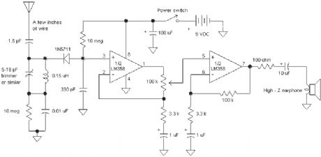
The Passive Aircraft Receiver is basically an amplified crystal radio designed to receive nearby AM aircraft transmissions. The passive design uses no oscillators or other RF circuitry capable of interfering with aircraft communications so it should be fine inside the cabin of the aircraft. Nevertheless, check the regulations before using this receiver on a commercial airliner. New security regulations probably prohibit this device on commercial flights. Do not expect to hear two-way aircraft transmissions with this receiver! It is a short-range receiver only.
The detector diode is a 1N5711, HP2835 or similar Schottky detector diode. The 10 megohm resistors provide a small diode bias current for better detector efficiency. The tuning capacitor may be any small variable with a range from about 5 pF to about 15 or 20 pF. The 0.15 uH inductor may be a molded choke or a few turns wound with a small diameter. Experiment with the coil to get the desired tuning range. The aircraft frequencies are directly above the FM band so a proper inductor will tune FM stations with the capacitor set near maximum capacity. (The FM stations will sound distorted since they are being slope detected.) Other capacitor and inductor combinations may be selected to tune other bands if desired. (Try the CB band at 27 MHz.) The LM358 dual op-amp draws under 1 ma so the battery life is quite long. A speaker amplifier may be added to drive a speaker or low-z earphone. The antenna can be a couple of inches if the receiver is near the transmitter or a couple of feet for maximum range. The selectivity is reduce as the antenna length is increased so best performance is achieved with the shortest acceptable antenna. Try increasing the 1.8 pF capacitor value when using very short antennas and decreasing it for long antennas. The receiver could be built into a small plastic box with a short antenna inside. (View)
View full Circuit Diagram | Comments | Reading(2210)
LED bar graph display pressure gauge circuit with integrated Silicon pressure sensor MPX5100A
Published:2012/8/28 1:07:00 Author:Ecco | Keyword: LED, bar graph display , pressure gauge, integrated Silicon, pressure sensor
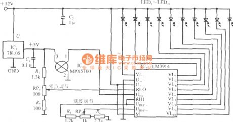
Its measuring range is 0~100kPa, resolution is 10kPa. +12V power can get +5V stabilized voltage output after passing three-side integrated voltage regulator 78L05, the maximum output current is up to 100mA, and it provides power for MPX5100 and LM3914. MPX5100's output voltage connects to UIN side of the LM3914. After the UREF+ end and RHI-side are connected in a short circuit, then UREF-end connects RP2, RP2 is full scale adjustment potentiometer. RP1 is zero scale adjustment potentiometer, when measured pressure is zero, adjusting RP1 can make all LEDs be hidden.
(View)
View full Circuit Diagram | Comments | Reading(3005)
Optically controlled relay switch with self-locking function composed of phototransistor
Published:2012/8/27 22:50:00 Author:Ecco | Keyword: Optically controlled , relay , switch, self-locking function , phototransistor
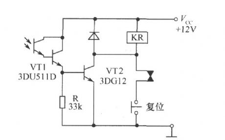
With Darlington phototransistor,the amplifier circuit is simplified, and the circuit only can usea 3DG medium power transistor to drive relays.
(View)
View full Circuit Diagram | Comments | Reading(3010)
Remote control starting up and shutdown circuit with installing VCD machine
Published:2012/8/27 22:57:00 Author:Ecco | Keyword: Remote control , starting up, shutdown , installing VCD machine
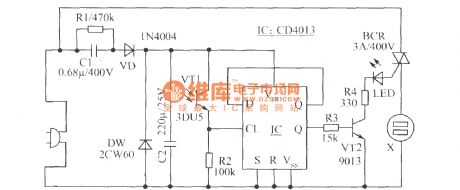
CD machine has a lot of remote control functions, but usually it does not have remote control starting up and shutdown function, and its power line is shorter. As shown in the figure, it is the remote control starting up and shutdown circuit which is added on CD machine.
Components selection; IC selects CMOS double D triggers CD4013. VT1 selects 3DU5 phototransistor. VT2 choose 9,013 NPN silicon tube, β>100. BCR selects 3A400V TRIAC such as TLC226 and so on. LED selects 5mm red light-emitting diode with any models. X selects 220V,10A flat dark socket. The remaining components are shown in the figure.
(View)
View full Circuit Diagram | Comments | Reading(3927)
| Pages:360/2234 At 20341342343344345346347348349350351352353354355356357358359360Under 20 |
Circuit Categories
power supply circuit
Amplifier Circuit
Basic Circuit
LED and Light Circuit
Sensor Circuit
Signal Processing
Electrical Equipment Circuit
Control Circuit
Remote Control Circuit
A/D-D/A Converter Circuit
Audio Circuit
Measuring and Test Circuit
Communication Circuit
Computer-Related Circuit
555 Circuit
Automotive Circuit
Repairing Circuit