
Circuit Diagram
Index 350
PULSE PERIOD TO VOLTAGE CONVERTER
Published:2012/9/6 19:58:00 Author:Ecco | Keyword: PULSE PERIOD , VOLTAGE CONVERTER
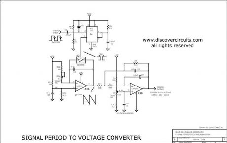
This is a test circuit converts a square wave input signal into a voltage. But, the voltage produced is proportional to the time between edges (period) of the signal, not the frequency. The range is from 100uS to to 10mS, which produces a voltage from 100mV to 10 volts. Other scale factors are also possible. The circuit is powered from single 15v supply and uses inexpensive parts. It is great when a signal's period instead of its frequency needs to be monitored.
Source: discovercircuits (View)
View full Circuit Diagram | Comments | Reading(2520)
Six-way flashing light string circuit (2) (HFC3040)
Published:2012/9/5 22:43:00 Author:Ecco | Keyword: Six-way, flashing light string
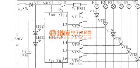
In the figure, LED1, LED2can be usedforboth power indicator and regulator,and itcan choose a common Φ5mm red light-emitting diode. VT7 ~ VT12select MCR100- 8 small plastic one-way thyristor (1A/600V).
(View)
View full Circuit Diagram | Comments | Reading(1722)
Gated automatic lamp circuit (2)
Published:2012/9/5 22:40:00 Author:Ecco | Keyword: Gated , automatic lamp
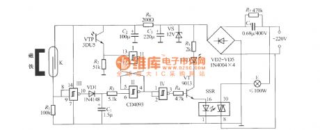
As shown in the figure, itis a gated auto light circuitwith digital integrated circuits, and it mainly consists of the door and window sensors, CD4093 digital integrated circuit, solid state relay, power supply circuit and other components. K can use JAG-4H reed pipe, small magnets should choose the small magnetic steelwith strong magnetism.
(View)
View full Circuit Diagram | Comments | Reading(1549)
Gated automatic lamp circuit (3)
Published:2012/9/5 22:37:00 Author:Ecco | Keyword: Gated automatic lamp
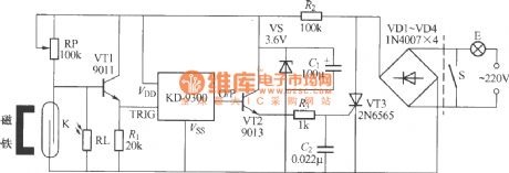
As shown in figure, the gated automatic light uses an ordinary music doorbell chip skillfully, it has the following main functions: ① When you return home at night and open the door, the lights can be automatically lit with 20s, so it avoid trouble from looking for light switch in the dark; ② During the day, switch is automatically blocked, and closing door won't light the lamp; ③ The wiring is simple, it can be directly connected in parallel at both ends of the light switch, then this lamp has gated and light control functions.
(View)
View full Circuit Diagram | Comments | Reading(819)
Neon bulb triggered Triac dimming light circuit
Published:2012/9/5 22:31:00 Author:Ecco | Keyword: Neon bulb , triggered , Triac dimming light

Neon bulb triggered Triac dimming light circuit is shown as the figure, and V is the Neon bulb. (View)
View full Circuit Diagram | Comments | Reading(2230)
Neon colored lantern with music sound control circuit
Published:2012/9/5 22:29:00 Author:Ecco | Keyword: Neon colored lantern , music sound , control circuit
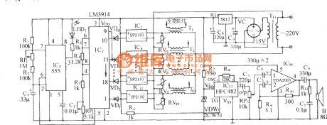
As shown in the figure, it is mainly composed of the multivibrator, graphics driver circuit, AC solid-state relay controller, songs sound circuit, amplifier circuit and AC buck rectifier circuit. It enables the 10 groups of neon lights to vagary with different lantern patterns, also accompanied by the world famous music. The time-base circuit 555 and R1 , R2 , C1 form a low-frequency harmonic oscillator, and its frequency: fo = 1.44 / (R1 + RRP1 +2 R2) C1. The oscillation frequency of the icon parameter is 0.035Hz to 0.15 Hz.
(View)
View full Circuit Diagram | Comments | Reading(1054)
Seven-way flashing light string circuit ( CS71017 )
Published:2012/9/5 22:17:00 Author:Ecco | Keyword: Seven-way , flashing light string
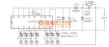
Its flashing mode can be freely programmed. The core device is seven programmable flash integrated circuit CS71017. iN The figure, VTH1 ~ VTH7 shoulduse MAC94A4 small plastic TRIAC with smaller trigger current.
(View)
View full Circuit Diagram | Comments | Reading(1066)
Three-way flashing light string circuit ( 2 ) ( LP167 )
Published:2012/9/5 22:14:00 Author:Ecco | Keyword: Three-way , flashing light string
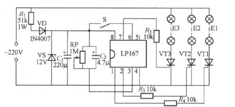
As shown in the figure, it is the three-way flashing light string controller with novel light control integrated circuit LP167. LP167 is the audio voltage controlled ASIC with DIP-8 package, and it integrates the audio rectification amplifier, voltage-controlled oscillator, three-bit ring timing and counting distributor and three open-drain follower.
(View)
View full Circuit Diagram | Comments | Reading(1657)
Dimming and timing dual - use table lamp circuit
Published:2012/9/5 22:09:00 Author:Ecco | Keyword: Dimming , timing , dual - use, table lamp
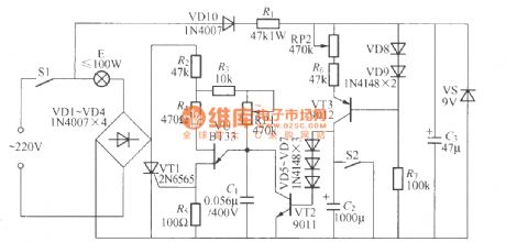
As shown in figure, the table lamp circuit can be used for stepless dimming, it also has a timing turn-off function, it is composed of delay circuit and transistor dimming circuit.
(View)
View full Circuit Diagram | Comments | Reading(983)
Multi-color advertising light box with music audible circuit ( 2 )
Published:2012/9/5 22:03:00 Author:Ecco | Keyword: Multi-color, advertising light box , music audible circuit

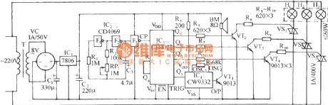
As shown in the figure, it consists of time-base pulse oscillator, counting / pulse distribution circuit, SCR drive lamp circuit and AC buck rectifier circuit. It enables advertising light box to make multi-color changes with red, green and blue, also accompanied by melodious songs play in order to attract more pedestrians and tourists. F1, F2, F3 are three gates of the six NOT gate integrated circuit CD4069; F1, F2, R2 and C3, etc. form a self-excited multivibrator and its oscillation frequency is:
The oscillation frequency of the icon parameteris 0.088 ~ 0.97Hz ( corresponding periodis about 1 to 11.4s ).
(View)
View full Circuit Diagram | Comments | Reading(1188)
Multifunction dimming desk lamp circuit ( HT7706 )
Published:2012/9/5 21:46:00 Author:Ecco | Keyword: Multifunction, dimming , desk lamp
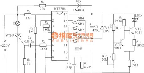
As shown in figure, it is a multifunctional dimming desk lamp circuit, it increases a photometric circuit, and it is very suitable for reading and writing.
(View)
View full Circuit Diagram | Comments | Reading(1149)
TEMPERATURE SENSOR WITH 4 TO 20mA CURRENT LOOP
Published:2012/9/5 21:08:00 Author:Ecco | Keyword: TEMPERATURE SENSOR, 4 TO 20mA , CURRENT LOOP
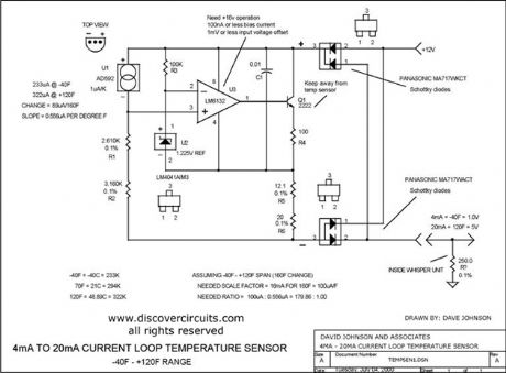
I designed a circuit similar to this one years ago to accurately measure the air temperature inside a building 1000s of feet from a control room. The circuit uses a very robust current loop method. It uses a highly accurate semiconductor temperature sensor and an equally accurate voltage reference. The circuit includes a diode bridge, so it is polarity independent. By using the component values indicated, the circuit should not require calibration. It has a range from ?40F to +120F and an accuracy of +/- one degree F.
Source: discovercircuits (View)
View full Circuit Diagram | Comments | Reading(1460)
Energy Harvesting Using a Current Transformer -- January 17, 2010
Published:2012/9/5 21:06:00 Author:Ecco | Keyword: Energy Harvesting , Current Transformer
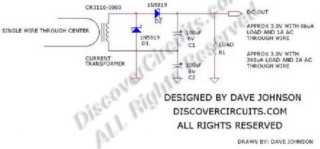
Energy harvesting is all the rage these days. With some modern electronics, information from low power sensors can be sent to a distant data collection point using a low power RF transmitter. To power these remote sensors, various energy sources can be tapped into. Machine vibration, temperature differences, ambient light and stray RF have all been used as low power energy sources. Sometimes, the sensors are located near AC power cables. Rather than making a direct connection to those cables, an AC current transformer, such as the one shown below, can be used to capture a bit of power.
Source: discovercircuits (View)
View full Circuit Diagram | Comments | Reading(1375)
CAPS PROVIDE VOLTAGE BOOST TO SERIES REGULATOR
Published:2012/9/5 21:05:00 Author:Ecco | Keyword: CAPS , VOLTAGE BOOST , SERIES REGULATOR

This circuit adds some capacitors and diodes to a traditional transformer type series regulator circuit to extend the normal operating range. It can insure regulation during low line voltage conditions or it can squeeze a few more watts out of a plug-in-the-wall power adapter power supply.
Source: discovercircuits (View)
View full Circuit Diagram | Comments | Reading(0)
18v AC to DC Power Supply
Published:2012/9/5 21:04:00 Author:Ecco | Keyword: 18v, AC to DC, Power Supply
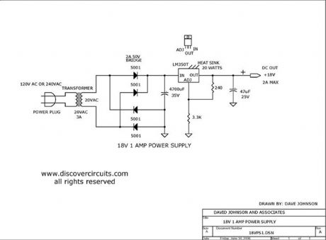
This is a classic linear power supply which produces a regulated 18v, rated at about 1 amp.
Source: discovercircuits (View)
View full Circuit Diagram | Comments | Reading(3068)
Computer Controlled 100ma Current Source (July 11, 2008)
Published:2012/9/5 21:03:00 Author:Ecco | Keyword: Computer Controlled, 100ma, Current Source
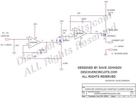
Often in industrial control systems a constant current source is needed, which is controlled by a computer and referenced to circuit ground. The circuit below converts a zero to 5v signal from a computer?s analog output into a current, with a full scale of 100ma. The circuit shown requires a 9v DC supply but any voltage from 9v to 12v will work.
Source: discovercircuits (View)
View full Circuit Diagram | Comments | Reading(2008)
AUDIO FREQUENCY DIGITAL NOISE GENERATOR
Published:2012/9/5 21:03:00 Author:Ecco | Keyword: AUDIO , FREQUENCY , DIGITAL , NOISE GENERATOR

When you need to test an audio circuit with broadband noise, this circuit works great. It uses just three inexpensive C-MOS ICs that generate a series of output pulses whose widths vary randomly. I included a level control pot.
Source: discovercircuits (View)
View full Circuit Diagram | Comments | Reading(4881)
5 VOLT MOMENTARY OPERATION TOUCH SWITCH
Published:2012/9/5 21:02:00 Author:Ecco | Keyword: 5 VOLT, MOMENTARY OPERATION , TOUCH SWITCH
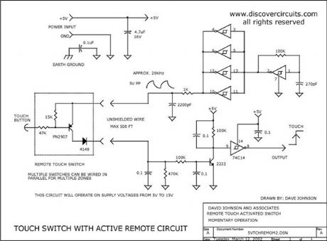
This simple circuit uses a single IC to form a nice touch switch circuit. A single transistor forms the remote active switch sensor. Multiple switches can be wired in parallel. The switch circuit can be located about 500 feet from the control circuit.
Source: discovercircuits (View)
View full Circuit Diagram | Comments | Reading(2390)
Pushbutton Activated Service Request Beeper
Published:2012/9/5 21:01:00 Author:Ecco | Keyword: Pushbutton , Activated Service Request, Beeper

A single press of a pushbutton switch turns on a beeper for one second but can?t be activated again for 60 seconds.
Source: discovercircuits (View)
View full Circuit Diagram | Comments | Reading(1851)
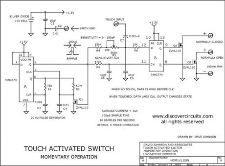
1.5V TOUCH ACTIVATED SWITCH
Published:2012/9/5 20:58:00 Author:Ecco | Keyword: 1.5V, TOUCH , ACTIVATED SWITCH
This circuit provides about one watt of non-isolated DC power for an automotive type 12v LED array lamp in addition to a standard incandescent table lamp.
Source: discovercircuits (View)
View full Circuit Diagram | Comments | Reading(1327)
| Pages:350/2234 At 20341342343344345346347348349350351352353354355356357358359360Under 20 |
Circuit Categories
power supply circuit
Amplifier Circuit
Basic Circuit
LED and Light Circuit
Sensor Circuit
Signal Processing
Electrical Equipment Circuit
Control Circuit
Remote Control Circuit
A/D-D/A Converter Circuit
Audio Circuit
Measuring and Test Circuit
Communication Circuit
Computer-Related Circuit
555 Circuit
Automotive Circuit
Repairing Circuit