
Circuit Diagram
Index 344
2 to 4 wire audio converter
Published:2012/9/10 21:04:00 Author:Ecco | Keyword: 2 to 4 wire , audio converter
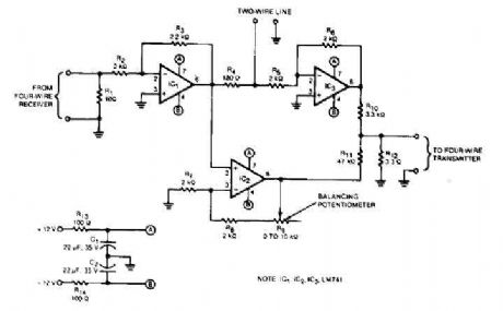
This audio converter circuit maintains 40 dB of isolation between the two halves of entry and exit of a four-line son, while allowing a line connecting two son. A balancing potentiometer, R, adjusts the gain of zero lC2to crossing the inlet to the outlet.
Source: discovercircuits (View)
View full Circuit Diagram | Comments | Reading(3775)
HiFi expandor with De-emphasis
Published:2012/9/10 21:04:00 Author:Ecco | Keyword: HiFi expandor , De-emphasis
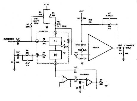
it can reduce its gain. The time it takes for the compressor to recover from overload is determined by the rectifier The expander eg capacitor to complete the compressor is shown in FIG. 2-13B. Here is an external op amp is used for the high rate of ascent. The compressor and expander have unity gain at 0 dB. Trim networks are shown for distortion (THD) and DC offset.
Source: discovercircuits (View)
View full Circuit Diagram | Comments | Reading(1)
High fidelity amplifier circuit
Published:2012/9/10 21:03:00 Author:Ecco | Keyword: High fidelity , amplifier
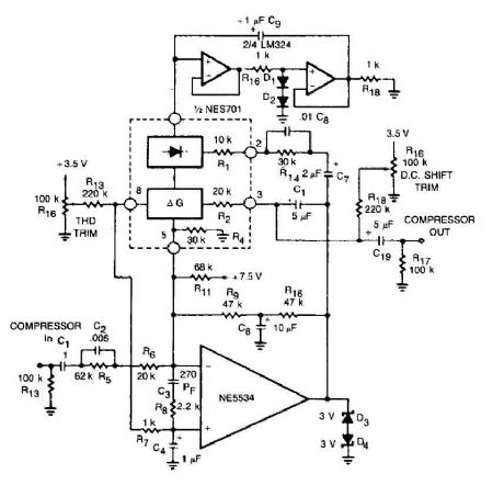
This circuit for a compressor uses a high-fidelity external op amp, and a high gain and wide bandwidth. A compensation network input is necessary for stability. The rectifier capacitor (Cg) is not grounded. but it is linked to the output of an op amp circuit.
Source: discovercircuits (View)
View full Circuit Diagram | Comments | Reading(1060)
Small current amplifier circuit
Published:2012/9/10 21:03:00 Author:Ecco | Keyword: Small current , amplifier
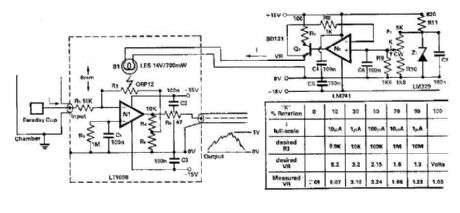
To amplify the small current signals as an electron collector inside a vacuum chamber, it is convenient for reasons of noise and bandwidth to have a head-amplifier attached to the chamber. Op N-amp 1 is a precision device with bipolar bias current and low offset voltage (1)-and the noise low, which allows the 100:1 attenuator comments to be used.
Source: discovercircuits (View)
View full Circuit Diagram | Comments | Reading(752)
GaAsFET amplifier circuit
Published:2012/9/10 21:02:00 Author:Ecco | Keyword: GaAsFET amplifier
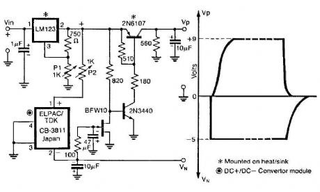
The control circuit operates to double from a positive supply, which, when turned on the power of the first door. and goes off when the first drain as shown in FIG. This circuit integrates the LM123, a three-terminal positive regulator and a dc dc + converter, whose output power drains and gates of GaAsFET-power relay in a power amplifier. The controller output drives a three-terminal DC + DC converter - which exit through an N-channel lFET properly so as to pull the base of the series pass transistor 2N6107 at a level to turn it on.
Source: discovercircuits (View)
View full Circuit Diagram | Comments | Reading(802)
Programmable gain amplifier
Published:2012/9/10 21:02:00 Author:Ecco | Keyword: Programmable gain , amplifier
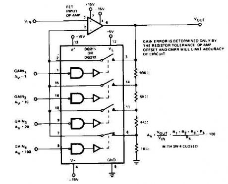
The circuit uses the DG212 which controlling the gain using resistors. To calculate the different gains SW4 should be closed. Gain error is determined only by the resistor tolerance op amp offset and CMR will limit accuracy of circuit.
Source: discovercircuits (View)
View full Circuit Diagram | Comments | Reading(0)
Offset controlled stereo amplifier circuit
Published:2012/9/10 21:02:00 Author:Ecco | Keyword: Offset controlled, stereo amplifier
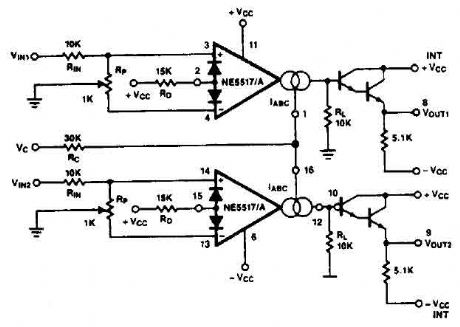
This stereo amplifier use the NE5517/A and has an excellent tracking of 0.3 dB typical easy. With the potentiometer, Rp, the offset can be adjusted. For AC-coupled amplifiers, the knob can be replaced by two resistors 5.1 k ohm.
Source: discovercircuits (View)
View full Circuit Diagram | Comments | Reading(2)
Unity gain Inverter amplifier circuit
Published:2012/9/10 21:01:00 Author:Ecco | Keyword: Unity gain , Inverter, amplifier
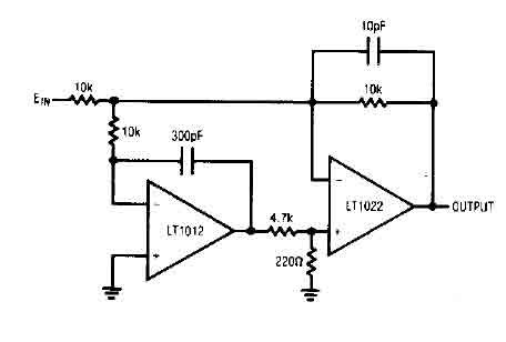
The circuit consists of a device with low drift LTl012. and a speed amplifier LTl022Jligh. The entire circuit is a unity gain inverter, with the summing node at the junction of three resistors 10k. The monitors what the Tl012 summing node, it compares to the mass, and drives the positive input LTI022, completing a loop to stabilize around the Tl022 L. The k 10 to 300 pF at the time constant LTI012 limit its response to low frequency signals. LTl022 handles the high-frequency inputs while LTl012 stabilizes the operating point.
Source: discovercircuits (View)
View full Circuit Diagram | Comments | Reading(1386)
Simple logarithmic amplifier circuit
Published:2012/9/10 21:01:00 Author:Ecco | Keyword: Simple , logarithmic, amplifier
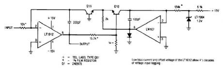
This simple logarithmic amplifier circuit use the LT1012 which has a low bias current allow 4 1/2 decades off voltage input logging.
Source: discovercircuits (View)
View full Circuit Diagram | Comments | Reading(2866)
High gain amplifier circuit
Published:2012/9/10 21:01:00 Author:Ecco | Keyword: High gain , amplifier
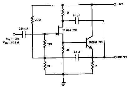
In this circuit nothing is left to chance in reducing input capacitance. The 2N5485, which has a very low-capacity legacy first, is always operated as a source follower with gate bias bootstrap.
Source: discovercircuits (View)
View full Circuit Diagram | Comments | Reading(2638)
2 Watt stereo amplifier with LM1877N-9
Published:2012/9/10 20:59:00 Author:Ecco | Keyword: 2 Watt , stereo amplifier
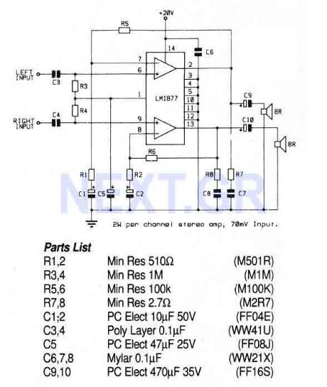
This circuit uses a stereo amplifier IC in a 14-pin DIL package that requires very few external components to make a complete 2 Watt per channel power amplifier.
Source: discovercircuits (View)
View full Circuit Diagram | Comments | Reading(1)
Stereo Preamplifier with balance and loudness
Published:2012/9/10 20:58:00 Author:Ecco | Keyword: Stereo Preamplifier , balance , loudness
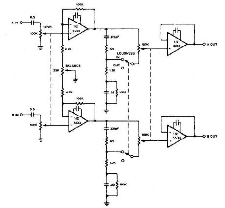
The circuit of preamplifier use the 5533 chip and features a combination of controls balance and volume. Due to the nonlinearity of the human auditory system, low frequencies must be boosted at low listening levels. Level pay, and LOUDNESS controls provide all the plays to produce the desired response from the music.
Source: discovercircuits (View)
View full Circuit Diagram | Comments | Reading(5078)
FSK Demodulator/Tone Decoder with RC2211N
Published:2012/9/10 20:58:00 Author:Ecco | Keyword: FSK Demodulator, Tone Decoder
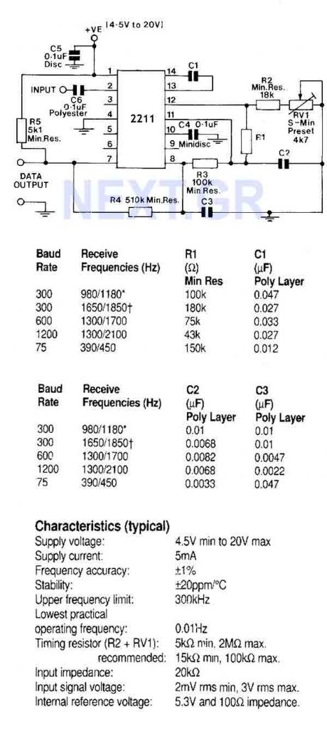
A monolithic phase locked loop for data communications. The IC contains a basic phase locked loop for tracking an input signal within the pass band, a quadrature phase detector which provided carrier detector and an FSK voltage comparator which provides FSK demodulation. In the circuit shown, the IC is used as an FSK demodulator such as would be found in the receiver circuit of a modem.
Source: discovercircuits (View)
View full Circuit Diagram | Comments | Reading(2938)
Audio compressor circuit
Published:2012/9/10 20:57:00 Author:Ecco | Keyword: Audio compressor
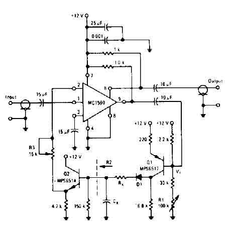
The amplifier drives the base of a common emitter PNP MPS6517 operating with a voltage gain of about 20. RL control varies the quiescent point of the transistor Q, so that varying amounts of signal exceed the level of V r, diode D 1 rectifies the positive peaks Ql output is only when these peaks are more larger than r V ' 7. 0 volts. The result is filtered ex Rx. s, controls the charging time constant or time of attack. Cx is involved in two loading and unloading. R2 (150 K, the input resistance of the emitter-follower Q2) controls the decay time.
Source: discovercircuits (View)
View full Circuit Diagram | Comments | Reading(5328)
Overload speaker protection circuit
Published:2012/9/10 20:56:00 Author:Ecco | Keyword: Overload speaker, protection
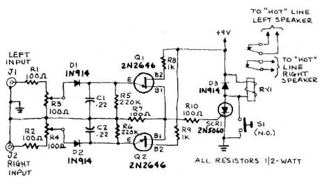
The circuit input is taken from the terminal loudspeaker or amplifier output jacks. If the right channel is large enough to charge C1 to a potential which exceeds the breakdown voltage of the emitter of Ql, a voltage pulse appears in R7. Similarly, if the left channel signal is large enough to charge C2 to a voltage that is greater than the breakdown voltage of the emitter of Q2 , a pulse appears in R7. The pulse triggers in R7 5CRI. A door sensitive SCR (LGT less than 15 RNA or IGT is the gate-trigger current) that locks in a conducting state and energizes Ryl. The action of the relay will interrupt the speaker circuit. and silence follows you must alert on the problem.
Source: discovercircuits (View)
View full Circuit Diagram | Comments | Reading(2091)
Q-multiplier filter circuit
Published:2012/9/10 20:56:00 Author:Ecco | Keyword: Q-multiplier, filter
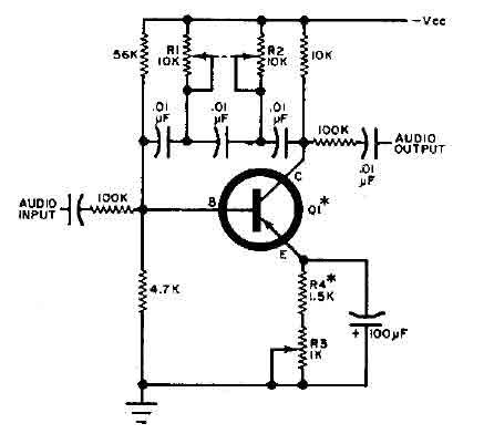
This circuit is selective for the tuning adjustment between two closely spaced tones audio. The frequency is dependent on the selective value capacitors and resistors in the feedback circuit between the collector and base of Q1. With the values shown, the frequency can be tuned to a hundred cycles or so-around 650 Hz Ri and R2 should be grouped. R3 potentiometer transmitter determines the sharpness of the response curve.
Source: discovercircuits (View)
View full Circuit Diagram | Comments | Reading(3040)
Automatic level control with NE570
Published:2012/9/10 20:56:00 Author:Ecco | Keyword: Automatic level , control
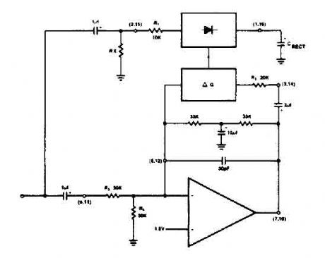
The NE570 can be used to make a high performance compressor FTA, except that the rectifier is connected to the input. This makes gain inversely proportional to the input level so that a drop of 20 dB input level will produce an increase of 20 dB gain. The output remains at a constant level. As shown, the circuit will maintain an output level of ± 1 dB for an input range of + 14 to -43 dB at 1 kHz.
Source: discovercircuits (View)
View full Circuit Diagram | Comments | Reading(2212)
Active crossover circuit with TL074
Published:2012/9/10 20:55:00 Author:Ecco | Keyword: Active crossover
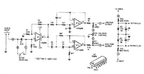
An audio source, like a mixer, preamp, EQ, or a recorder, is fed to the input of the Electronic Crossover Circuit. This signal is either AC or coupling, depending on the setting of switch 51, the non-inverting input of buffer amplifier Ul-a, a section of a quad BIFET, low amp TL074 noise made by Texas Instruments op. This stage has a gain of 2, and its output is distributed to both a low pass filter made by R4, R5, C2, C3, and Uld op-amp, and a high-pass filter made by R6, R7, C4 , C5, and op amp ULC. These are12 dB / octave Butterworth filters. The response of the Butterworth filter was chosen because it gives the best compromise between the damping and phase.
Source: discovercircuits (View)
View full Circuit Diagram | Comments | Reading(5413)
Automatic audio fader circuit
Published:2012/9/10 20:55:00 Author:Ecco | Keyword: Automatic, audio fader
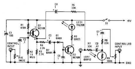
The automatic fader drops at the background music while the narration is in place. The control input through RIO, a preset audio level control, into an emitter-follower buffer stage CQI). The buffer provides high input impedance and ensures that the source impedance is low enough to drive the rectifier and smoothing circuit, consisting of DI, D2, and C5. The smoothed output drives a simple LED circuit. LD and R8 form an IR input pad through which the output is fed through C6 and C7 to the output jack.
Source: discovercircuits (View)
View full Circuit Diagram | Comments | Reading(4247)
Amplifier Compressor MC3340P
Published:2012/9/10 20:54:00 Author:Ecco | Keyword: Amplifier , Compressor
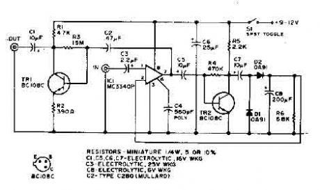
This audio compressor circuit use a MC3340P as a variable gain amplifier. The output is rectified and TR2 controls the gain of the ICL ..
Source: discovercircuits (View)
View full Circuit Diagram | Comments | Reading(3608)
| Pages:344/2234 At 20341342343344345346347348349350351352353354355356357358359360Under 20 |
Circuit Categories
power supply circuit
Amplifier Circuit
Basic Circuit
LED and Light Circuit
Sensor Circuit
Signal Processing
Electrical Equipment Circuit
Control Circuit
Remote Control Circuit
A/D-D/A Converter Circuit
Audio Circuit
Measuring and Test Circuit
Communication Circuit
Computer-Related Circuit
555 Circuit
Automotive Circuit
Repairing Circuit