
Circuit Diagram
Index 340
HiFi expandor with De-emphasis
Published:2012/9/11 21:25:00 Author:Ecco | Keyword: HiFi expandor , De-emphasis
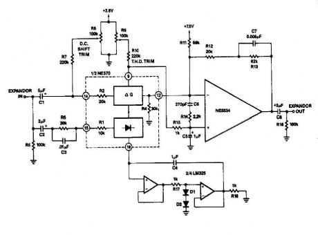
it can reduce its gain. The time it takes for the compressor to recover from overload is determined by the rectifier The expander eg capacitor to complete the compressor is shown in FIG. 2-13B. Here is an external op amp is used for the high rate of ascent. The compressor and expander have unity gain at 0 dB. Trim networks are shown for distortion (THD) and DC offset. (View)
View full Circuit Diagram | Comments | Reading(3531)
2 to 4 wire audio converter
Published:2012/9/11 21:24:00 Author:Ecco | Keyword: 2 to 4 wire, audio converter
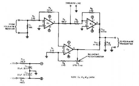
This audio converter circuit maintains 40 dB of isolation between the two halves of entry and exit of a four-line son, while allowing a line connecting two son. A balancing potentiometer, R, adjusts the gain of zero lC2to crossing the inlet to the outlet. (View)
View full Circuit Diagram | Comments | Reading(0)
Audio compressor circuit
Published:2012/9/11 21:22:00 Author:Ecco | Keyword: Audio compressor
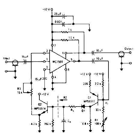
The amplifier drives the base of a common emitter PNP MPS6517 operating with a voltage gain of about 20. RL control varies the quiescent point of the transistor Q, so that varying amounts of signal exceed the level of V r, diode D 1 rectifies the positive peaks Ql output is only when these peaks are more larger than r V ' 7. 0 volts. The result is filtered ex Rx. s, controls the charging time constant or time of attack. Cx is involved in two loading and unloading. R2 (150 K, the input resistance of the emitter-follower Q2) controls the decay time. (View)
View full Circuit Diagram | Comments | Reading(0)
Automatic level control with NE570
Published:2012/9/11 21:20:00 Author:Ecco | Keyword: Automatic level , control
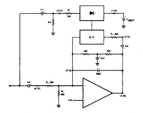
The NE570 can be used to make a high performance compressor FTA, except that the rectifier is connected to the input. This makes gain inversely proportional to the input level so that a drop of 20 dB input level will produce an increase of 20 dB gain. The output remains at a constant level. As shown, the circuit will maintain an output level of ± 1 dB for an input range of + 14 to -43 dB at 1 kHz. (View)
View full Circuit Diagram | Comments | Reading(0)
Metal Detector circuit with TDA2822
Published:2012/9/11 21:19:00 Author:Ecco | Keyword: Metal Detector

Here is a simple metal detector with TDA2822 and few NPN transistors. There is a small arrow connected from the Emitter of the T3 to the 10n Capacitor C4. That arrow is simply indicating signal flow as right to left in that particular wire, which is different from the remaining circuit's left to right. (View)
View full Circuit Diagram | Comments | Reading(3778)
Analogue to digital converter circuit
Published:2012/9/11 21:19:00 Author:Ecco | Keyword: Analogue to digital, converter
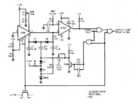
That simple 4 digits converter circuit has OUTPUT COUNT = 1 according to my f-IMHz to 10.000. All diodes are IN4146 POLYSTYRENE NPO. (View)
View full Circuit Diagram | Comments | Reading(3848)
16 bit Analogue to Digital Converter LTC1052
Published:2012/9/11 21:18:00 Author:Ecco | Keyword: 16 bit, Analogue to Digital , Converter
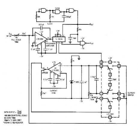
The circuit here is a A/D converter, that consisting of A2, a flip-flop, some doors and a current sink, is based on a current balancing technique. Again, the stabilized LTC 1052 50 no drift of V input 1 ° C is necessary to eliminate the offset errors of aid. (View)
View full Circuit Diagram | Comments | Reading(1835)
10 Bit A-D converter circuit
Published:2012/9/11 21:18:00 Author:Ecco | Keyword: 10 Bit , A-D converter
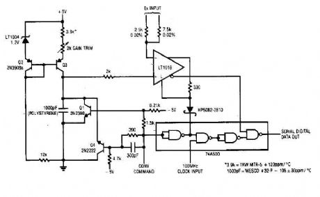
Each time a pulse is applied to the conversion of the control input, Ql resets the 1000 pF capacitor to 0 V. This action takes 200 ns to reset the falling edge of the convert command pulse, the capacitor begins to charge linearly. In exactly 10 microseconds, it loads to 2.5 V. The ramp is 10 microseconds applied to the positive input of the LTl016. The LT1016 compares the ramp Ex, the unknown, its negative input. For a 0 V - 2.5 V range, Ex is applied to the resistance of 2.5 k ohm. (View)
View full Circuit Diagram | Comments | Reading(1631)
A/D Converter with LT1018
Published:2012/9/11 21:18:00 Author:Ecco | Keyword: A/D Converter
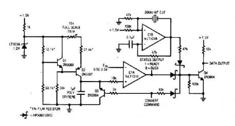
The converter has a 60-ms conversion consumes 460 pA of 1's. 5 V power supply and maintains an accuracy of 10 bits on a 15 ° C in the temperature range of 35 ° C. A pulse applied to convert the command line causes Q3, operating in reverse mode, the discharge path through the diode 10 kO, forcing its collector low. Q3 results of reverse mode switching in a capacitor discharge to 1 mV of ground. During the time of the ramp value is less than the input voltage, output of the CIA is low. (View)
View full Circuit Diagram | Comments | Reading(1503)
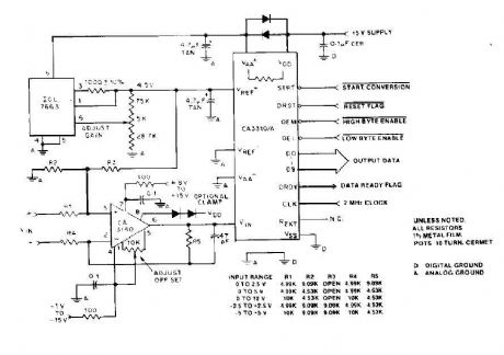
High Speed A/D converter 12-bit
Published:2012/9/11 21:17:00 Author:Ecco | Keyword: High Speed , A/D converter, 12-bit
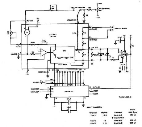
This system performs a complete conversion of 12 bits in 10 p unipolar or bipolar. This converter is accurate to ± 12-bit LSB Y2 and a typical gain TC of 10 ppm / ° C. In unipolar mode, the system range is 0 V to 9.9976 V, with each bit having a value of 2.44 mY. For the accuracy of true conversion, an A / D converter must be trimmed so that, given the results just the exit code of input levels of Y2 Y2 LSB LSB below to above the exact voltage represents the code. (View)
View full Circuit Diagram | Comments | Reading(1417)
Simple A/D converter circuit with 2504
Published:2012/9/11 21:16:00 Author:Ecco | Keyword: Simple A/D converter
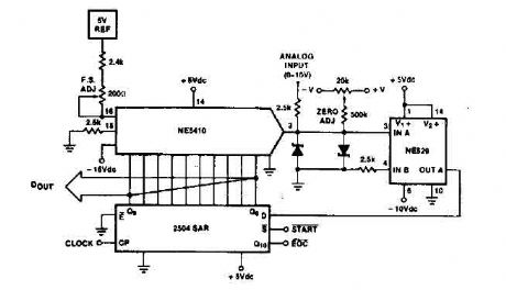
Time IO-bit conversion is 3.3 MHz with a p 3. Clock. This converter uses an approximation 2504 12-bit register in successive operating mode where the short-cycle end signal conversion is taken from the first bit used in the SAR (QLO). (View)
View full Circuit Diagram | Comments | Reading(1132)
14 Bit A-D Converter with ICL7134B
Published:2012/9/11 21:16:00 Author:Ecco | Keyword: 14 Bit , A-D Converter
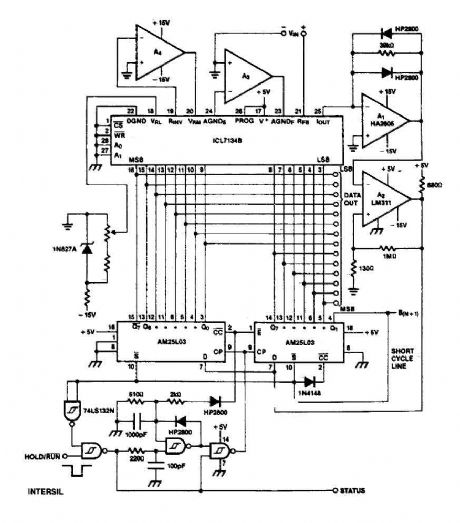
The circuit ICL7134B base is a bipolar input AID converter broadband, using two AM25L03s to form a successive approximation register 14-bit. The comparator is a circuit with two stage amplifier HA2605 front, used to reduce the settling time problems in the pro summing node (see A020). Warning nu11ing offset of this amplifier is needed and if wide temperature range operation is desired, an auto-zero circuit using a lCL7650 is probably desirable (see A053). The clock, using two gates TTL Schmitt trigger operates at a slower pace for the first 8 bits, where the settlement time is more critical than for the last 6 bits. (View)
View full Circuit Diagram | Comments | Reading(1490)
Cyclic A/D converter circuit
Published:2012/9/11 21:15:00 Author:Ecco | Keyword: Cyclic A/D converter
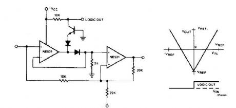
The cyclic converter consists of a chain of identical stages, each of which detects the polarity of the input. Step V REF then subtracted from the double entry and the rest if the polarity is correct. The signal is full wave rectified and the rest of V IN - V REF is doubled. (View)
View full Circuit Diagram | Comments | Reading(1051)
Differential A/D Converter circuit CA3110
Published:2012/9/11 21:15:00 Author:Ecco | Keyword: Differential, A/D Converter
By using an op amp BiMOS CA3140 provides good orientation skills for high bandwidth signal input, and can quickly adjust the energy output at its terminal CA33IO WINE. The CA3140 can also lead to near the negative supply rail. (View)
View full Circuit Diagram | Comments | Reading(1700)
Tone Doorbell circuit
Published:2012/9/11 21:14:00 Author:Ecco | Keyword: Tone Doorbell
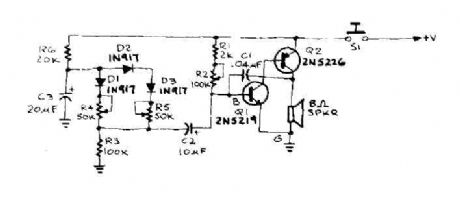
When the door is pushed, you hear a whisper that slide up to a higher frequency. The oscillator frequency is determined by AF coupling capacitance, C 1 and the value of the resistor connected between the base of IQ and the earth. This resistance, RBG is equal to (Ri + R2) RJ. First, suppose that 51 is closed and R2 have been adjusted to produce a pleasant, low frequency tone. The capacitor C3 charges through R6 until it reaches such a tension that will cause diode Dl to conduct. (View)
View full Circuit Diagram | Comments | Reading(1263)
Car windshield wiper delay
Published:2012/9/11 21:03:00 Author:Ecco | Keyword: Car, windshield , wiper, delay
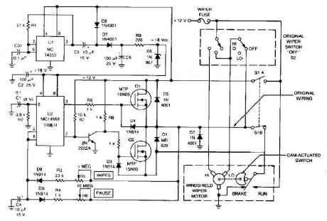
The circuit provides a windshield wiper delay, dynamic braking and windshield wipers when they reach the rest position. This prevents the blades passing, which could lead them to stop at a point where they interfere with the vision of drivers. With the original wiper switch off, switch turns on the MLS delay circuit and disconnects the wiring SIB from automobiles. When SI is turned off, the original wiring system and controls the delay circuit is bypassed. (View)
View full Circuit Diagram | Comments | Reading(1)
RIAA preamplifier CA3410
Published:2012/9/11 21:02:00 Author:Ecco | Keyword: RIAA , preamplifier
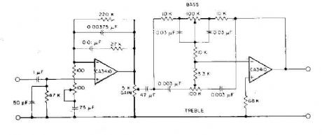
This circuit has read the RIAA equalization, tone controls, and adequate gain to drive most power amplifiers conunercial by using CA3410 op amp BiMOS. Total harmonic distortion, pushed to provide an output of 6-V, is less than 0.035% in audio-frequency range from 150 Hz to 40 kHz. Full stereo preamp is to duplicate this circuit using the CA3410 remaining two amplifiers. (View)
View full Circuit Diagram | Comments | Reading(0)
CAR IMMOBILIZER CIRCUIT
Published:2012/9/11 21:01:00 Author:Ecco | Keyword: CAR IMMOBILIZER
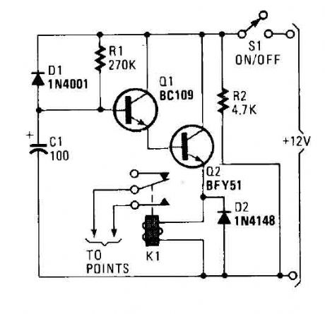
A flip of 51 puts the system in action. Power for the circuit is captured from the ignition switch, and circuit receives no power until the ignition switch is closed. When the camera is turned on, the capacitor C1 is charged and the emitter follower Darlington pair (formed by Q1 and Q2) are cut, so no voltage is applied to the relay (Kl), which serves as a load QL transmitter. normally open relay contacts are connected through the points of the vehicle. (At this point, the relay contacts are open and have no effect on the ignition system). Cl charges through R, causing the voltage at the base of Ql to rise steadily. (View)
View full Circuit Diagram | Comments | Reading(1)
Car Wiper-Speed Controller
Published:2012/9/11 20:59:00 Author:Ecco | Keyword: Car, Wiper-Speed Controller
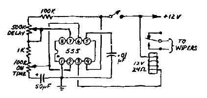
This 12V wiper speed controller circuit uses the 555 timer. And can be fitted to any car. Its one of those very easy and usefull circuits. (View)
View full Circuit Diagram | Comments | Reading(1)
Car Voltmeter Circuit
Published:2012/9/11 20:59:00 Author:Ecco | Keyword: Car Voltmeter
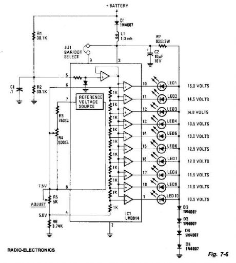
This screen uses ten LEDs to display a voltage range of 10.5 to 15 volts. Each LED represents a step 0.5wvolt tension. The heart of the circuit is the 3914 points LM / bar display driver. Trimming potentiometer R5 is adjusted so that 7.5 volts is applied to the upper side of the bulkhead. D2 resistor R7 and diode D5 to tighten the voltage applied to the LED 3 volts. A lowpass filter consisting of L1 and C2 guards against voltage spikes. The diode D1 is used to protect against reverse voltage where the voltmeter is connected backwards. (View)
View full Circuit Diagram | Comments | Reading(2036)
| Pages:340/2234 At 20321322323324325326327328329330331332333334335336337338339340Under 20 |
Circuit Categories
power supply circuit
Amplifier Circuit
Basic Circuit
LED and Light Circuit
Sensor Circuit
Signal Processing
Electrical Equipment Circuit
Control Circuit
Remote Control Circuit
A/D-D/A Converter Circuit
Audio Circuit
Measuring and Test Circuit
Communication Circuit
Computer-Related Circuit
555 Circuit
Automotive Circuit
Repairing Circuit