
Circuit Diagram
Index 332
Bedini SG Energiser
Published:2012/9/16 21:53:00 Author:Ecco | Keyword: Bedini SG Energiser
John Bedini has been working in what is sometimes known as the free energy field for 35 years now. He would be amongst the first to correct this description as he would describe himself as involved with Free Radiant Energy which is not the same thing i.e. he is harnessing a form of energy little understood by the most of us. (View)
View full Circuit Diagram | Comments | Reading(4533)
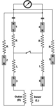
Swiss ML Testakica
Published:2012/9/16 21:52:00 Author:Ecco | Keyword: Swiss , ML Testakica
The Unit is started by hand by revolving the two disks in opposite directions and continues to move without further input. This device has only two moving parts namely the bearing races at the centre of the disk. The disk are made of clear plastic upon which are placed flat a series of fifty blade type steel or aluminium sections equally spaced around the middle sections of each disk. The speed of the revolving disks is about 50 to 60 rpm limited to this by magnetic impulses from the magnetic section on the rim. (View)
View full Circuit Diagram | Comments | Reading(1127)
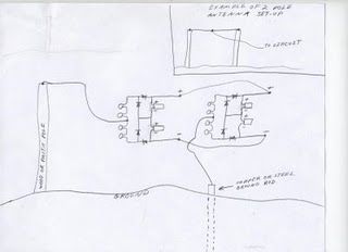
Tesla's Energy Reciever
Published:2012/9/16 21:52:00 Author:Ecco | Keyword: Tesla, Energy Reciever
Tesla's free-energy receiver was patented in 1901 as An Apparatus for the Utilization of Radiant Energy. The patent refers to the Sun, as well as other sources of radiant energy, like cosmic rays. That the device works at night is explained in terms of the night-time availability of cosmic rays. Tesla also refers to the ground as a vast reservoir of negative electricity. . (View)
View full Circuit Diagram | Comments | Reading(1570)
Kapanadze Free Energy Generator
Published:2012/9/16 21:52:00 Author:Ecco | Keyword: Kapanadze , Free Energy , Generator
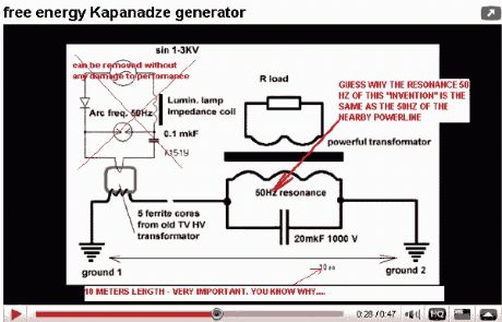
Georgia Republic inventor, Tariel Kapaladze, claims to have invented a 5 kilowatt free energy generator. In a demonstration video, the device appears to produce copious amounts of energy from no visible source. Though it appears to be extracting energy from the aether, some people think it could be a matter of getting energy from the electrical grid through inductive coupling. (View)
View full Circuit Diagram | Comments | Reading(6441)
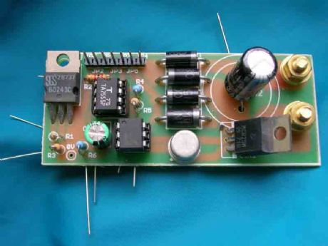
Bedini Circuit
Published:2012/9/16 21:51:00 Author:Ecco | Keyword: Bedini
The power is all in the timed switching process. There are two main principles I use of switching the radiant energy the John Bedini way. First, the SG/SSG, Icehouse unidirectional circuit or John Bedini Monopole with the School Girl Circuit (SG) Mechanical-Oscillator-Energizer and second, the John Bedini/Ron Cole switching oscillator circuit. Since my SSG4a/SG4a is a John Bedini/Ron Cole switching oscillator circuit, I should have called it BC4a meaning Bedini/Cole4a. (just to get the facts straight :) The main difference is the transistor arrangement of the first, usually in parallel, meaning for every wire a transistor/multiplying the J. Bedini circuit on the same heat-sink, which is used mainly for charging batteries and driving the rotor. (View)
View full Circuit Diagram | Comments | Reading(2924)
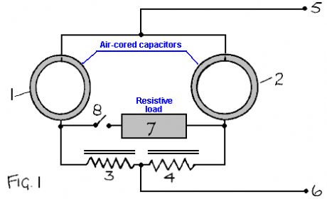
Free heater circuit by Rosemary Ainslie
Published:2012/9/16 21:51:00 Author:Ecco | Keyword: Free heater, Rosemary Ainslie
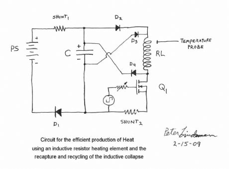
Rosemary's original test circuit is shown in the article she tried to have published in a refereed scientific journal, but the submission was always rejected. In the last 5 months, I have had extensive email correspondence, and numerous telephone conversations with Rosemary, who lives in South Africa. After studying her work, I was absolutely thrilled with her discovery of the super-efficient heating effect. In mid-February of this year, I proposed to her an idealized schematic of her DC resonance circuit to produce the effects she had discovered. (View)
View full Circuit Diagram | Comments | Reading(8858)
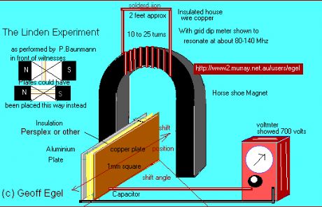
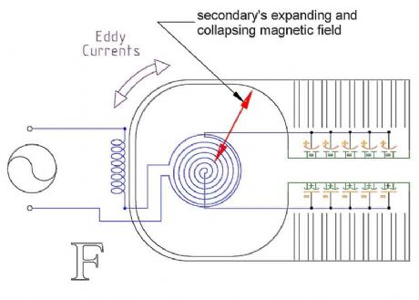
Free Energy Circuit
Published:2012/9/16 21:50:00 Author:Ecco | Keyword: Free Energy
This type of design can produce a very high amperage current for a faction a second that can used to do some useful work if properly harnessed. A point to remember is that Paul Baumann built his first device in prison and as such did not have access to exotic materials as is often described in other theories of how the Testakica was said to have worked. One would conclude from this, that as such, that the home experimenter should also be able to build such a device from material from around the house. (View)
View full Circuit Diagram | Comments | Reading(1945)
12 coil Pulse Monopole/Generator
Published:2012/9/16 21:50:00 Author:Ecco | Keyword: 12 coil, Pulse Monopole, Generator
Fully functional Bedini motor pulse charger powered by micro-controller. All variables (coil sensitivity thresh-hold and motor power (current) consumption) controlled by software program. I can manipulate triggering of motor and triggering of cap pulse disharge. Results have convinced me this is the cheaper way to build and experiment. I haven't blown any components yet with this experiment with no protection Neon (Ne2) on transistor. (View)
View full Circuit Diagram | Comments | Reading(2217)
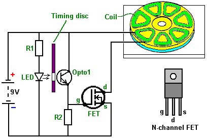
Free energy Bicycle lights
Published:2012/9/16 21:49:00 Author:Ecco | Keyword: Free energy, Bicycle lights
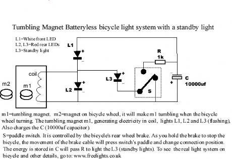
This bicycle safety flashing light system is based on a newly invented electrical generating system, NO battery needed, No friction on any parts of the bicycle. No drag. get the energy almost free (at least on bicycle). Very bright. Standby light. (View)
View full Circuit Diagram | Comments | Reading(4139)
Hans Coler Passive Circuit
Published:2012/9/16 21:49:00 Author:Ecco | Keyword: Hans Coler Passive
He called this device the Stromerzeuger and for a few watts from a dry battery it provided 6 kW continuously. He was refused development support because it was a perpetual motion machine. Hans also invented a passive device which he called the Magnetstromapparat. His unit required very careful and slow adjustment to get it operating but when it started it continued on test in a locked room for three months of continuous operation. (View)
View full Circuit Diagram | Comments | Reading(1638)
Free energy Schematic II
Published:2012/9/16 21:49:00 Author:Ecco | Keyword: Free energy
If you decide to use 2 circuits, i just connect their outputs together...neg output from first circuit to neg output of second circuit & pos output from first circuit to pos output of second circuit. And take readings from same place....from where you conected the 2 circuits together. (View)
View full Circuit Diagram | Comments | Reading(1517)
Motionless Pulsed Energy Generators
Published:2012/9/16 21:48:00 Author:Ecco | Keyword: Motionless Pulsed, Energy Generators
A solid-state electrical generator including at least one permanent magnet, magnetically coupled to a ferromagnetic core provided with at least one hole penetrating its volume; the hole(s) and magnet(s) being placed so that the hole(s) intercept flux from the permanent magnet(s) coupled into the ferromagnetic core. A first wire coil is wound around the ferromagnetic core for the purpose of moving the coupled permanent magnet flux within the ferromagnetic core. A second wire is routed through the hole(s) penetrating the volume of the ferromagnetic core, for the purpose of intercepting this moving magnetic flux, thereby inducing an output electromotive force. A changing voltage applied to the first wire coil causes coupled permanent magnet flux to move within the core relative to the hole(s) penetrating the core volume, thus inducing electromotive force along wire(s) passing through the hole(s) in the ferromagnetic core. (View)
View full Circuit Diagram | Comments | Reading(2229)
Free Energy device
Published:2012/9/16 21:48:00 Author:Ecco | Keyword: Free Energy
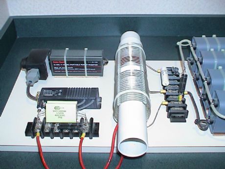
This is a simple straight forward machine that was basically designed in the 1890's by Nikola Tesla and modified for modular circuitry by Don Smith. There are so many ways to do this that it boggles the mind, but this circuit will power what you need. This setup with a 120v-30 amp isolation transformer is capable of 3600 watts continuous before overheating the transformer! It will handle much larger transformers and multiple transformers. (View)
View full Circuit Diagram | Comments | Reading(5506)
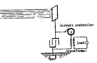
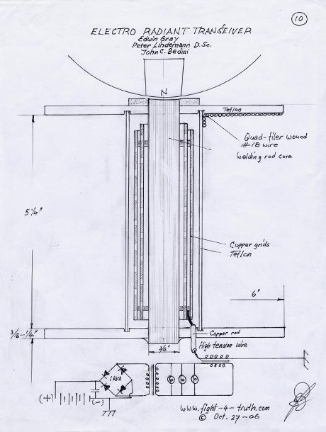
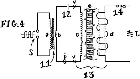
Utilisation of Radiant Energy
Published:2012/9/16 21:47:00 Author:Ecco | Keyword: Utilisation , Radiant Energy
This was filed on 21 March 1901 and granted on 5 November 1901. It was entitled: 'Apparatus for the Utilisation of Radiant Energy'. By installing two metal plates, one high above the ground and the other at ground level, with wires connecting the plates to separate electrodes of a capacitor, it was stated that the capacitor became charged to a very high potential, the energy input being that radiated to Earth from outer space. This may well have motivated the efforts of T. Henry Moray but, so far as this Applicant's invention is concerned, no such input from overhead components is necessary as a quite different energy source is at work, namely the zero-point vacuum energy activity of our quantum. (View)
View full Circuit Diagram | Comments | Reading(1343)
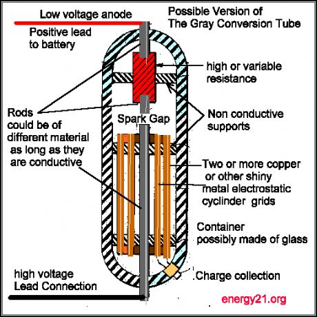
Electret Circuit
Published:2012/9/16 21:47:00 Author:Ecco | Keyword: Electret
Arcing completes a circuit -- closes a system -- between two voltage potentials. When arcing occurs, two oppositely charged static voltage potentials can cancel each other out. The arcing problems that occur are usually between two electrically isolated voltage potentials pressures necessary to hold a charge and they are part of the same circuit -- completes a closed system. (View)
View full Circuit Diagram | Comments | Reading(931)
Solid State Free energy Circuit
Published:2012/9/16 21:47:00 Author:Ecco | Keyword: Solid State, Free energy
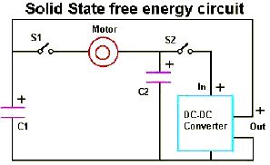
It's very simple actually. The idea is that we use what we have learned from the capacitor tests to create a circuit that uses the capacitors to run the load and then by discharging the 1/2 full capacitor into a DC-DC converter we can recharge the initial cap and start again. And have some energy left over. (View)
View full Circuit Diagram | Comments | Reading(4680)
Free energy Battery Charger
Published:2012/9/16 21:46:00 Author:Ecco | Keyword: Free energy , Battery Charger
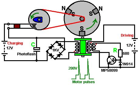
With this system, the rotor is started spinning by hand. As a magnet passes the triple-wound tri-filar coil, it induces a voltage in all three coil windings. The magnet on the rotor is effectively contributing energy to the circuit as it passes the coil. One winding feeds a current to the base of the transistor via the resistor R. This switches the transistor hard on, driving a strong current pulse from the battery through the second coil winding, creating a North pole at the top of the coil, boosting the rotor on its way. As only a changing magnetic field generate a voltage in a coil winding, the steady transistor current through coil two is unable to sustain the transistor base current through coil one and the transistor switches off again. (View)
View full Circuit Diagram | Comments | Reading(13285)
Simple self-powered circuit
Published:2012/9/16 21:46:00 Author:Ecco | Keyword: simple self-powered
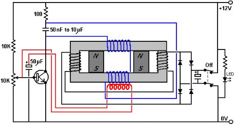
This simple circuit is started running by connecting a twelve volt battery across the terminals, causing the large diameter Light-Emitting Diode to light up. When the battery is removed, the LED stays lit up because the circuit has become self-powering. While, at this scale, this is not a particularly useful project, it is an interesting one because conventional science says that it is quite impossible to do this. (View)
View full Circuit Diagram | Comments | Reading(2930)
Free energy magnet motor
Published:2012/9/16 21:44:00 Author:Ecco | Keyword: Free energy , magnet motor
This invention relates to a method of producing useful energy with magnets as the driving force and represents an important improvement over known constructions and it is one which is simpler to construct, can be made to be self starting, is easier to adjust, and is less likely to get out of adjustment. The present construction is also relatively easy to control, is relatively stable and produces an amazing amount of output energy considering the source of driving energy that is used. (View)
View full Circuit Diagram | Comments | Reading(6841)
Self runner Generator
Published:2012/9/16 21:42:00 Author:Ecco | Keyword: Self runner Generator
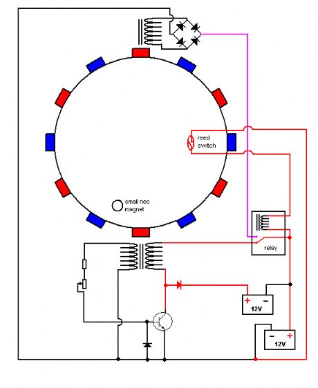
The timing must be exact to get those high voltage spikes. I used a tiny magnet on the rotor, that triggered a reedswitch allowing the relay to pulse the energy from the recovery coil to the primary battery. In the same time the rest of the circuit is disconnected form the primary battery. The recovery coil has to have at least 20Ohms resistance, the higher the better, because when the speed rises at startup, you can see on the meter, that the voltage across the recovery coil increases. (View)
View full Circuit Diagram | Comments | Reading(3805)
| Pages:332/2234 At 20321322323324325326327328329330331332333334335336337338339340Under 20 |
Circuit Categories
power supply circuit
Amplifier Circuit
Basic Circuit
LED and Light Circuit
Sensor Circuit
Signal Processing
Electrical Equipment Circuit
Control Circuit
Remote Control Circuit
A/D-D/A Converter Circuit
Audio Circuit
Measuring and Test Circuit
Communication Circuit
Computer-Related Circuit
555 Circuit
Automotive Circuit
Repairing Circuit