
Circuit Diagram
Index 355
Pyroelectric infrared sensing automatic lamp circuit (7)
Published:2012/9/3 22:30:00 Author:Ecco | Keyword: Pyroelectric , infrared sensing, automatic lamp
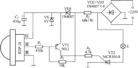
As shown in the figure, it is a inductive automatic light with RDP-18 pyroelectric infrared sensor module, and RDP-18 is a new module produced by Jiangnan radio factory which is located in Jinhua, Zhejiang, and it integrates pyroelectric infrared control circuit, PIR sensor and Fresnel lense, so the circuit is very simple.
(View)
View full Circuit Diagram | Comments | Reading(5766)
Pyroelectric infrared sensing automatic lamp circuit (9)
Published:2012/9/3 22:39:00 Author:Ecco | Keyword: Pyroelectric, infrared sensing , automatic lamp

As shown in the figure, it is a inductive automatic light with TWH9512 pyroelectric infrared sensor dedicated module, and it can be used for occasions such as bathroom, storage room, stairs aisle lights control, and it can realize that lights are lit when people come, and turned off when people leave. At the same time, it also has light control circuit, and it can automatically close circuit during the day, so the lights will not be lit. Another feature of the switch is that it uses two-wire connection, so you don't need to change the original indoor wiring, you can directly replace the normal power switch, then the lights are reconfigured as infrared lamps automatically.
(View)
View full Circuit Diagram | Comments | Reading(2430)
Dual-channel radio remote control light switch circuit
Published:2012/9/3 22:26:00 Author:Ecco | Keyword: Dual-channel, radio , remote control , light switch
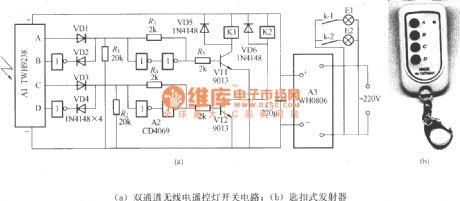
As shown in the figure, it is a dual-channel radio remote control light switch circuit with dedicated radio transmitter and receiver modules, and it can independently control the on-off of two lamps, and the circuit structure is very simple.
Figure b shows the key chain emitter.
(View)
View full Circuit Diagram | Comments | Reading(3554)
Dual flashing light string circuit ( 1 )
Published:2012/9/3 22:20:00 Author:Ecco | Keyword: Dual , flashing light string
As shown in the figure, it is a two-way flashing light string controller. After getting power, it can make light strings E1 and E2 flash alternately, this circuit can also be transformed commercially double-headed ( lights) wall lamp, and two lights will flash alternately.
(View)
View full Circuit Diagram | Comments | Reading(1132)
Dual flashing light string circuit (3 )
Published:2012/9/3 22:09:00 Author:Ecco | Keyword: Dual, flashing light string
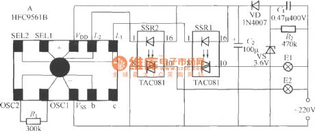
As shown in the figure, it is a dual flashing string lights controller which uses HFC9561B audio integrated circuit skillfully. HFC9561B ( produced by Wenzhou Fenghua Electronic Co., Ltd.) is also known as the four-tone alarm integrated circuit.
(View)
View full Circuit Diagram | Comments | Reading(1048)
Double-control lamp switch circuit
Published:2012/9/3 21:45:00 Author:Ecco | Keyword: Double-control, lamp switch
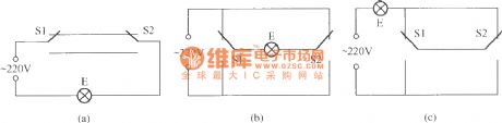
Dual - control switch is also known as the double switch, it is generally installed in two different places of the up-down layer or aisle, and it can independently control the on-off of the same lamp. The FIG provides three different connections, S1 , S2 are 1 x 2 single pole double throw switch which can independently control the on-off of lamp E. In Figure (b), each switch has the phase line and zero line of power supply, so the installation is more convenient, but it need to pay special attention to the short circuit of phase and zero lines' two ends in maintenance.
(View)
View full Circuit Diagram | Comments | Reading(1298)
Four-way flashing light string circuit ( 4 ) ( CS9801 )
Published:2012/9/3 20:56:00 Author:Ecco | Keyword: Four-way , flashing light string
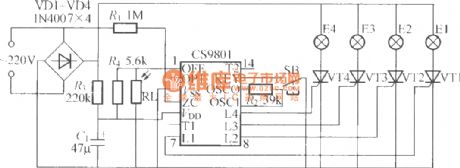
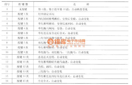
As shown in figure, it is a four-way flashing light string controller CS9801 with ASIC, it has four outputs; single-key cycle can control 16 kinds of tricks, and choose 16 paragraphs or the first 8 paragraphs of patterns, the following 8 paragraphs of patterns. The circuit also has a photo-resistor RL which allows light string to be automatically turned off during the day, flash at night; This circuit is very suited to control a Christmas tree. RL can choose the MG45 photosensitive resistor or thyristor MCR100-8. The following table shows the 16 patterns stored in CS9801.
(View)
View full Circuit Diagram | Comments | Reading(1279)
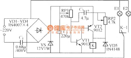
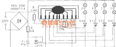
Four-way flashing light string circuit ( 5 ) ( 5G169 )
Published:2012/9/3 21:13:00 Author:Ecco | Keyword: Four-way, flashing light string
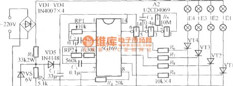
As shown in the figure, it is a four-way flashing light string controller with 5G169 light controlled ASIC produced by Shanghai Components factory 5. It can make the four-way light string E1 ~ E4 be lit in a cycle, and it can automatically change the brightness and cycle direction of the light string. Regulating RP1 can change the the lantern string flowing rate, adjusting RP2 can change the degree of light string's gradual brightness ( dimming fade or bright ); thyristor can use MCR100-8.
(View)
View full Circuit Diagram | Comments | Reading(997)
Four-way flashing light string circuit ( 6 ) ( SH-123 )
Published:2012/9/3 21:26:00 Author:Ecco | Keyword: Four-way , flashing light string
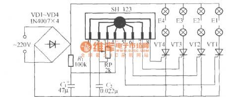
As shown in the figure, it is a water-flowing and horse-running four-way flashing light string controller, and its core component is an SH-123 holiday light controlled ASIC. VT1 ~ VT4 are available in MCR100-8 thyristor, and each road lantern's power should be below 100W.
(View)
View full Circuit Diagram | Comments | Reading(3078)
Four-way flashing light string circuit ( 8 )
Published:2012/9/3 21:30:00 Author:Ecco | Keyword: Four-way , flashing light string
As shown in the figure, it is a multi - pattern four-way flashing light string controller with ASIC SH-803, SH-803 has eight kinds of program methods and a variety of dimming speeds, and it can select a program pattern by trigger controlling terminal. VT1 ~ VT4 should use MCR100-8 thyristors; pressing SB can choose any patterns change.
(View)
View full Circuit Diagram | Comments | Reading(5350)
Low Power Under- and Over-Voltage Monitor
Published:2012/9/4 1:47:00 Author:Ecco | Keyword: Low Power , Under- and Over-Voltage, Monitor
This voltage monitor has two threshold, VTH for undervoltage and VTH’ for overvoltage. Using the component values shown in the schematic diagram below, this circuit give 6V for VTH and 15V for VTH1. Above 6V, the LED indicator of this voltage monitor circuit will increase the flash rate until reach 15V. This circuit will stop flashing at voltage below 6V and above 15 volts since there will be no current flowing through C1. At threshold boundary, the output of LM10 will saturate to negative below VTH and saturate to positive above VTH’.
To customize circuit we can select the resistors values according to chosen VTH and VTH’ using the following formula:
VTH=[R4(R1+R2)Vref]/[R1(R3+R4)];
VTH’=[R4(R1+R2)Vref]/[R1(R3+R4)-R3(R1+R2)]
Since the current consumption is very small (around 500uA), this voltage monitor will be suitable for various application demanding low cost solution, such as battery monitoring, small testing equipments, or power line indication.
(source: freecircuitdiagram)
(View)
View full Circuit Diagram | Comments | Reading(2230)
5V FET Voltage Regulator
Published:2012/9/4 1:45:00 Author:Ecco | Keyword: 5V , FET , Voltage Regulator
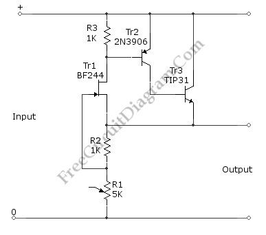
This voltage regulator circuit gives a stable 5V output from unregulated inputs (more than 5V). The stability of the output voltage is good enough, only change less than 0.1 volts when the load current changes about 60mA. Here is the schematic diagram of the circuit:
The basic principle of the voltage regulation rely on the mechanism of keeping the the FET’s gate voltage at the cut-off point. The FET’s gate volage is the voltage across R2. At zero volt (when there is no current flowing through R2), the FET will be conducting, and a small current at FET (Tr1) will cause much larger current to flow through Tr3. This current will flow through R2 and the gate voltage becomes negative. A some level the negative voltage at FET’s gate will cut-off the FETs current and keep the output voltage stable. (source: freecircuitdiagram)
(View)
View full Circuit Diagram | Comments | Reading(1842)
26V-to-5000V DC-DC Converter
Published:2012/9/4 1:44:00 Author:Ecco | Keyword: 26V-to-5000V, DC-DC Converter
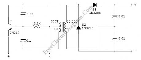
This circuit can provide 5,000 VDC from 26 VDC. This circuit has ripple of under 0.01% due to Voltage-doubling capacitors. As sinusoidal oscillator, a 2N217 transistor is used. The diode and the capacitors at the output stage should be of high voltage type. Here is the schematic diagram of the circuit:
(source: freecircuitdiagram)
(View)
View full Circuit Diagram | Comments | Reading(952)
Transceiver Saver (Overvoltage Protector)
Published:2012/9/4 1:42:00 Author:Ecco | Keyword: Transceiver Saver , Overvoltage Protector

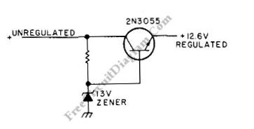

This is a transceiver saver circuit that protect a transceiver device (applicable to other device as well) from overvoltage of the power supply. This circuit is used to protect the device by regulating the power supply, avoiding damaging the device if overvoltage occurs. If the transceiver transmits current of above 2A, a heatsink should be used for the transistor. The value of resistor must provide output of 12.6 V during normal operation, you can make trial and error through measurement when choosing this., you can start with value around 100R. It’s recommended to use a high wattage Zener diode. Here is the schematic diagram of the circuit: (source: freecircuitdiagram)
(View)
View full Circuit Diagram | Comments | Reading(821)
Auto-Off 12V NiCd Battery Charger
Published:2012/9/4 1:40:00 Author:Ecco | Keyword: Auto-Off , 12V , NiCd Battery Charger
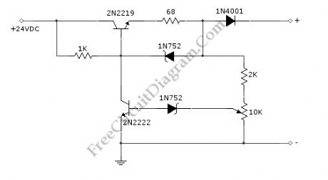
NiCd/NiCad battery charger circuit is still needed since some application demanding high current is still rely on NiCd type, since this type is still superior in term of high current output (low internal resistance) and low cost. This battery charger circuit is used to charge 12V NiCd battery at around 74 mA until battery is fully charged. This circuit need around 4 hours to fully recharge a totally empty/dead battery, depends on the battery capacity. Here is the schematic diagram of the circuit:
This circuit is basically a current source with auto cut-off. The current regulation is done by maintaining a fix voltage across a 68R at the emitter of 2N2219 transistor. This voltage is stabilized by a 5.6V zener diode 1N752, which keep the voltage at 68R resistor at around 5V, giving a constant current of 74 mA. The auto-off feature work by monitoring the output voltage (before the 1N4001 diode) relative to ground, as this voltage increases in accordance with the battery voltage which is being charged. After the battery voltage reach the fully-charged level, the lower 1N752 zener diode will pass the current to activate the 2N222 transistor, which short the upper transistor’s base, turning off the charging process. To calibrate the shut off point, connect a 270 ohm / 2 Watt resistor across the charge terminal and adjust the pot until the charging terminal voltage show 15.5V level.
(View)
View full Circuit Diagram | Comments | Reading(2994)
Foldback Current Limited High Voltage Regulator
Published:2012/9/4 1:36:00 Author:Ecco | Keyword: Foldback , Current Limited, High Voltage , Regulator
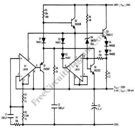
This circuit is high voltage regulator which has foldback current limiter protection. This circuit uses LM10 comparator with voltage reference, and this core integrated circuit is connected directly to high voltage circuitry. This high voltage direct connection is possible since the IC is inserted to a bias network and directly drop the applied voltage, so this IC is only suffering small voltage across its supply pins.
The foldback current limiter is different with ordinary current limiter in the way the limiter responds to dynamic load. When we plot the regular current limiter, when the load draw a linearly increasing current, the plot of the current will be linear ramp which stops at a specified level determined by the limiter. A foldback current limiter will give same response until the current reach the maximum level, but will fold the current back to a much lower current level if the load try to further increase the current. This foldback action will prevent the final driver transistor in the regulator from overheating. (source: freecircuitdiagram)
(View)
View full Circuit Diagram | Comments | Reading(1797)
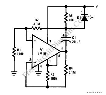
LM10 Battery Voltage Threshold Indicator
Published:2012/9/4 1:33:00 Author:Ecco | Keyword: Battery , Voltage Threshold , Indicator
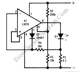
A battery threshold indicator circuit shown in the schematic diagram below has current regulation mechanism in driving the LED. A sufficient current should be satisfied at the minimum voltage but no excessive current when the voltage is at the highest level. Balance pin (5) is used as the reference voltage for regulating the current. This pin generate 23 mV, which is internally temperature compensated.
This battery voltage threshold indicator circuit overcomes the difficulties caused by voltage change across the diode biasing resistor.
When the voltage on the reference-feedback terminal (8) drops below 200 mV, the reference output (1) rises to supply the feedback voltage to the op amp through D2, so the LED current drops to zero. The minimum threshold voltage for these circuits is basically imited by the bias voltage for the LEDs. Typically, this is 1.7V for red, 2V for green and 2.5V for yellow. These two circuits can be made to operate satisfactorily for threshold voltages as low as 2V if a red diode is used. (source: freecircuitdiagram)
(View)
View full Circuit Diagram | Comments | Reading(0)
Direct High Voltage DC Regulator
Published:2012/9/4 1:31:00 Author:Ecco | Keyword: Direct, High Voltage, DC Regulator
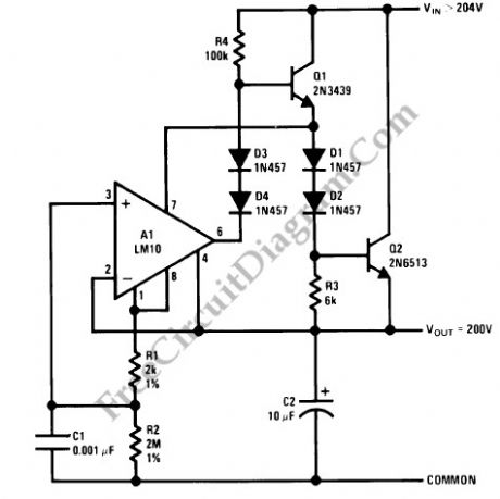
This regulator circuit stabilize the output voltage at 200V directly (without a transformer). Although the output voltage is high, this circuit only suffer a tension of the voltage drop (Vinput-Voutput), which is suffered mainly by the transistors. The op-amp suffers even less tension, since it regulate the applied voltage at their pins around the level of transistor’s bias voltage level.
(source: freecircuitdiagram)
(View)
View full Circuit Diagram | Comments | Reading(1773)
Overvoltage Protector with Relay
Published:2012/9/4 1:29:00 Author:Ecco | Keyword: Overvoltage Protector , Relay
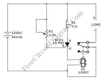
An overvoltage protector circuit is shown in the schematic diagram below. This circuit will work to disconnect the protected device from the power supply when an overvoltage occurs at the supply. This circuit uses a silicon-controlled rectifier (SCR) and normally-closed 12-V relay, K1. The silicon-controlled rectifier is connected in parallel to 12-V line to monitor for the overvoltage condition. This applied signal is sensed by the SCR’s gate. Here is the schematic diagram of the circuit:
The K1′s contacts remain closed and SCR1 remains off as long as the applied voltage stays below a preset value. When overvoltage occurs, the SCR1 will be triggered causing K1′s contacts open and halt current flow to the load. R1 is used to set the trigger point of SCR1.(source: freecircuitdiagram)
(View)
View full Circuit Diagram | Comments | Reading(1700)
Logic Power Control for 78xx Regulator
Published:2012/9/4 1:28:00 Author:Ecco | Keyword: Logic Power Control, Regulator
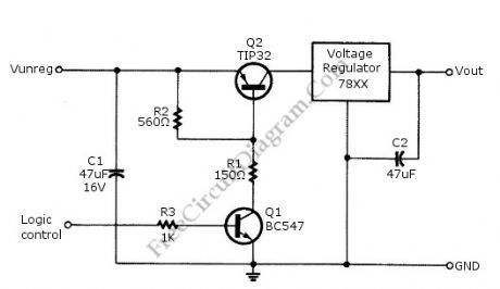

Logic power control of analog regulator can be useful in application where a digital circuit/controller need to control power source, such as in EEPROM programmer or other power controls. This is a circuit provide ON-OFF control for 78xx regulator using digital (TTL or CMOS) signal level. This circuit uses transistors in series with the 78XX regulator, which it’s base is controlled by logic level input. Here is the schematic diagram of the circuit: (source: freecircuitdiagram)
(View)
View full Circuit Diagram | Comments | Reading(1690)
| Pages:355/2234 At 20341342343344345346347348349350351352353354355356357358359360Under 20 |
Circuit Categories
power supply circuit
Amplifier Circuit
Basic Circuit
LED and Light Circuit
Sensor Circuit
Signal Processing
Electrical Equipment Circuit
Control Circuit
Remote Control Circuit
A/D-D/A Converter Circuit
Audio Circuit
Measuring and Test Circuit
Communication Circuit
Computer-Related Circuit
555 Circuit
Automotive Circuit
Repairing Circuit