
Circuit Diagram
Index 303
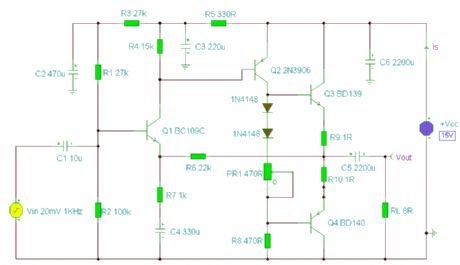
5 Watt Class-A Audio Amplifier
Published:2012/10/12 22:52:00 Author:muriel | Keyword: 5 Watt , Class-A, Audio Amplifier
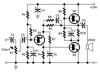
In the old valve days, most commercial audio amplifiers suited for compact integrated mono or stereo record players used a one-valve amplifier topology. The circuit was usually implemented by means of a multiple type valve, e.g. a triode pentode ECL86. Common features for those amplifiers were: Class A operation, output power in the 3 - 5W range, input sensitivity of about 600mV for full output power, THD of about 3% @ 3W and 1KHz. Best types showed THD figures of 1.8% @ 3W and 0.8% @ 2W. This solid-state push-pull single-ended Class A circuit is capable of providing a sound comparable to those valve amplifiers, delivering more output power (6.9W measured across a 8 Ohm loudspeaker cabinet load), less THD, higher input sensitivity and better linearity. (View)
View full Circuit Diagram | Comments | Reading(2455)
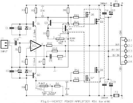
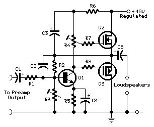
45W HEXFET Power Amplifier
Published:2012/10/12 22:51:00 Author:muriel | Keyword: 45W , HEXFET , Power Amplifier
View full Circuit Diagram | Comments | Reading(1222)
3 Band Equalizer
Published:2012/10/12 22:50:00 Author:muriel | Keyword: 3 Band, Equalizer
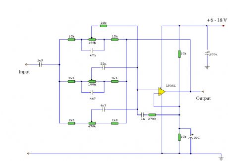
A tone control circuit made with a single op-amp and having three ranges, bass, middle and treble controls.
Notes:Using a single op-amp this easy to make equalizer offers three ranges, low frequency,mid frequency,and high. With component values shown there is approximately +/-20dB of boost or cut at frequencies of 50Hz, 1kHz and 10kHz. Supply voltage may be anything from 6 to 30 Volts. Maximum boost 20dB is only realized with maximum supply voltage of 18 Volt. (View)
View full Circuit Diagram | Comments | Reading(3581)
A 32 Watt per channel stereo power amplifier
Published:2012/10/12 22:49:00 Author:muriel | Keyword: 32 Watt, per channel , stereo , power amplifier
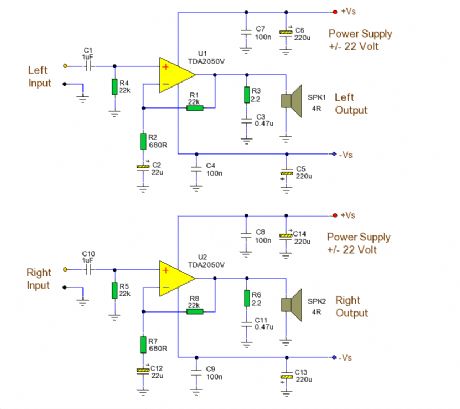
A 32 Watt per channel stereo power amplifier made using the TDA2050V monolithic integrated circuit. NotesThis circuit is for a 32 Watt stereo audio power amplifier using the TDA20501. With a dual 22 Volt supply this amplifier can deliver 32W into 8 ohm loudspeakers. Moreover, the TDA 2050 delivers typically 50W music power into 4 ohm load over 1 sec at VS= 22.5V and f = 1KHz.
This is a power amplifier and requires 200mV RMS for full output. Voltage gain is 30.5dB with resistor values shown. Closed loop gain is set by Ratio R1/R2. Increase R2 for less gain and vice versa. Power bandwidth is 20Hz to 80KHz. R3, C3 and R6, C11 form a zobel network to prevent high frequency instability.The speaker is direct coupled, therefore no expensive large value electrolytics are needed and the bass will be crisp and clean. It is advisable to place fuses in the power supply (not shown). (View)
View full Circuit Diagram | Comments | Reading(2227)
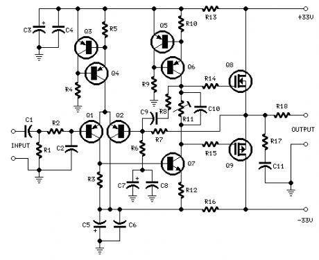
30-W MosFet Audio Amplifier
Published:2012/10/12 22:48:00 Author:muriel | Keyword: 30-W, MosFet, Audio Amplifier
This project was a sort of challenge: designing an audio amplifier capable of delivering a decent output power with a minimum parts count, without sacrificing quality. The Power Amplifier section employs only three transistors and a handful of resistors and capacitors in a shunt feedback configuration but can deliver more than 18W into 8 Ohm with <0.08% THD @ 1KHz at the onset of clipping (0.04% @ 1W - 1KHz and 0.02% @ 1W - 10KHz) and up to 30W into a 4 Ohm load.
(View)
View full Circuit Diagram | Comments | Reading(1954)
30w + 30w GUITAR AMPLIFIER
Published:2012/10/12 22:46:00 Author:muriel | Keyword: 30w + 30w, GUITAR AMPLIFIER
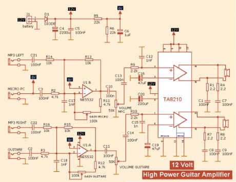
View full Circuit Diagram | Comments | Reading(1390)
300 Watt MOSFET HI-FI Power Amplifier
Published:2012/10/12 22:45:00 Author:muriel | Keyword: 300 Watt, MOSFET, HI-FI, Power Amplifier
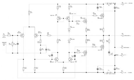
The amplifier consists of two completely separate monaural amplifiers each channel has its own power supply, resulting in zero inter-channel cross talk, a common phenomenon in amplifiers sharing the same power supply. In order to obtain the full output power each supply transformer should be rated at 40VAC - 0 - 40VAC at 640VA. Unlike many designs relying on the reservoir capacitors to supply peak currents, I prefer to have the raw power available from the transformer resulting in much faster transients.
Although the RAS 300 specifications are moderate, when listening to it you will immediately experience the massive reserve power available and never have any cause of anxiety that something is going to give in that one would when driving many amplifiers loud. You will hear nothing but reality with no distortion at any level and I guarantee that this amplifier will divulge the best qualities of any equipment connected to it.
(View)
View full Circuit Diagram | Comments | Reading(2852)
3 Channel Spectrum Analyzer
Published:2012/10/12 22:44:00 Author:muriel | Keyword: 3 Channel, Spectrum Analyzer
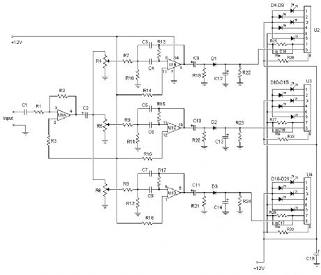
This 3 channel 15 LED spectrum analyzer is the perfect addition to any audio amp project. It produces fantastic displays on three LED bars that can be individually adjusted for any particular frequency range. The circuit will take line level output from most any audio source, and operates on 12V DC. This means that it can even be run in a car. (View)
View full Circuit Diagram | Comments | Reading(1462)
Amplifier 2x30W with STK465
Published:2012/10/12 22:43:00 Author:muriel | Keyword: Amplifier, 2x30W, STK465
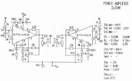
A amplifier of acoustic frequencies can be manufactured with discernible materials, despite is known so much the difficulties of finding of materials, what the problem of regulations. These difficulties are overcome relatively easily if we find amplifier in form completed.
Completed STK465 is an amplifier of acoustic frequencies that offers qualitative output, using minimal exterior elements. Substantially he is one of big completed force. Has a line pins and incorporated metal surface for adaptation in cooler. The provision pins in a line, facilitates the placement completed in the end printed and his support in cooler. The circuit functions in a big range of benefits of catering, from 20V as 60V, and it attributes 30WRMS, when the tendency of catering is above 50V and composer resistance of loudspeaker is the 4 or 8 Ohm. The catering should be symmetrically.
When it functions with tendency 56V then the tendency will be ± 28V as for the ground. With this recommended tendency of catering, the attributed force is 30 WRMS in charge 8W. The price of deformity is acceptable and oscillates around in the 0,08% for force of expense from 1W until 30W. Curve response his it is extended from 10Hz and reaches 100 KHz, with divergence 0dB and -3dB respectively, measured in force 1W. Using evolved techniques, completed amplifier STK465, can minimise the deformities even in highest levels of force. Other characteristically that determines the completed circuit they are: the wide area and the high aid.
(View)
View full Circuit Diagram | Comments | Reading(971)
two transistor operation
Published:2012/10/12 22:42:00 Author:muriel | Keyword: two transistor
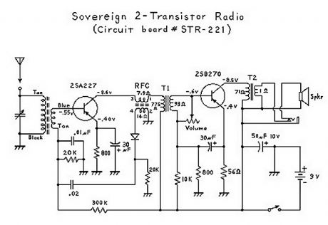
It has been interesting analyzing these radios. You have to give the Japanese credit for even making a radio that can drive a speaker with only 2 transistors! Basically, the first transistor (Q1) performs double-duty. It first acts as an RF amplifier, with some of the signal being fed back to the antenna coil to provide some regeneration for better selectivity and sensitivity. (This also results in a non-linear amplification of the signal which results in noticeable distortion.) The RF (radio frequency) signal is then rectified ( detected ) by the diode, and then the resultant audio signal is fed back to the base of the first transistor where it acts as the first AF (audio frequency) amplifier. (This is called a reflex circuit.) The audio signal is then fed through an interstage transformer to Q2 (the second transistor). The transformer provides impedance matching. The second transistor acts as a power amplifier, with the output signal going through an audio output transformer (to provide impedance matching again), and then finally to the speaker. Everything about this circuit is designed to provide maximimum gain; consequently there is no AGC (automatic gain control), and stronger stations come in a lot louder than weaker stations; unlike 6-transistor (or more) radio circuits which have an AGC circuit or function. (View)
View full Circuit Diagram | Comments | Reading(2026)
2N3055 Power Amplifier
Published:2012/10/12 22:41:00 Author:muriel | Keyword: 2N3055, Power Amplifier
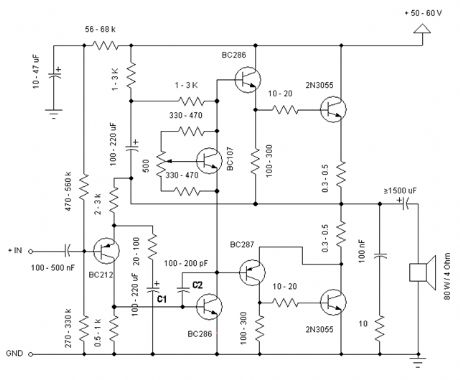
Simple and low cost. The optimal supply voltage is around 50V, but this amp work from 30 to 60V. The maximal input voltage is around 0.8 - 1V. As you can see, in this design the components have a big tolerance, so you can build it almost of the components, which you find at home. The and transistors can be any NPN type power transistor, but do not use Darlington types... The output power is around 60W. (View)
View full Circuit Diagram | Comments | Reading(2579)
25W Mosfet audio amplifier
Published:2012/10/12 22:40:00 Author:muriel | Keyword: 25W, Mosfet, audio amplifier
View full Circuit Diagram | Comments | Reading(1169)
21W Class AB amplifier
Published:2012/10/12 22:37:00 Author:muriel | Keyword: 21W, Class AB, amplifier

This is an instrument amplifier for monitoring music when on stage. It provides 21W output power of this little design. Previously I had a decent 10W amplifier (RED Free Circuits), but we blew that one somehow. Now I will put this into the old box. I haven't built it yet, but the simulations say it works as I designed. In this design, wiring is important due to no differential amplifier. I might need to add ripple rejection with a zener as in the above design.
(View)
View full Circuit Diagram | Comments | Reading(1974)
20W Bridge Audio Amplifier
Published:2012/10/12 22:35:00 Author:muriel | Keyword: 20W, Bridge, Audio Amplifier
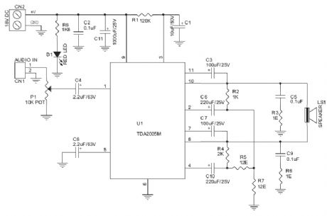
20W Bridge Audio Amplifier kit, based on the TDA2005 IC, a class B dual audio amplifier, specifically designed for car radio applications etc.
Power supply - 18 VDC
Output power - 20 W, 4 Ω
IC built in Thermal Shut-down, Load dump voltage surge protected
Terminal pins for connecting left and right audio signal inputs
Relimate Connector for connecting Potentiometer (POT) for volume adjustment
Power Battery Terminal (PBT) for easy power supply and speaker connection
Power-On LED indicator
Heatsink for IC
Four mounting holes of 3.2 mm each with nut and stud
PCB dimensions 63 mm x 65 mm (View)
View full Circuit Diagram | Comments | Reading(1805)
22 Watt Stereo Amplifier
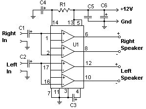
Published:2012/10/12 22:34:00 Author:muriel | Keyword: 22 Watt, Stereo Amplifier
View full Circuit Diagram | Comments | Reading(942)
22 Watt Audio Amplifier
Published:2012/10/12 22:33:00 Author:muriel | Keyword: 22 Watt, Audio Amplifier
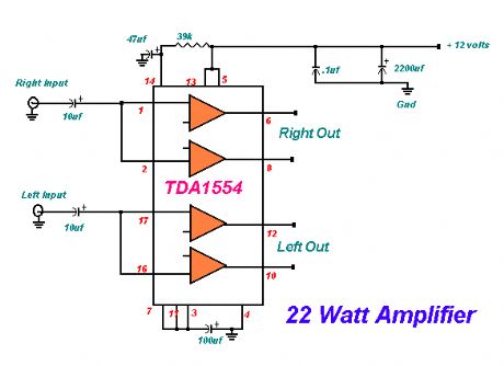
The 22 watt amp is easy to build, and very inexpensive. The circuit can be used as a booster in a car audio system, an amp for satellite speakers in a surround sound or home theater system, or as an amp for computer speakers. The circuit is quite compact and uses only about 60 watts. The circuit is not mine, it came from Popular Electronics.
(View)
View full Circuit Diagram | Comments | Reading(1306)
personal stereo audio amplifier
Published:2012/10/12 22:32:00 Author:muriel | Keyword: personal, stereo, audio amplifier
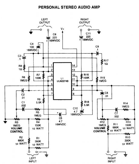
View full Circuit Diagram | Comments | Reading(2016)
2 Watt audio amplifier made from discrete components.
Published:2012/10/12 22:31:00 Author:muriel | Keyword: 2 Watt, audio amplifier
This was one of the earliest circuits that I ever designed and built, in Spring 1982. At that time I had only an analogue meter and a calculator to work with. Although not perfect, this amplifier does have a wide frequency response, low harmonic distortion about 3%, and is capable of driving an 8 ohm speaker to output levels of around 5 watts with slightly higher distortion. Any power supply in the range 12 to 18 Volts DC may be used. The amplifier operates in Class AB mode; the single 470R preset resistor, PR1 controls the quiescent current flowing through the BD139/140 complimentary output transistors. Adjustment here, is a trade-off between low distortion and low quiescent current. Typically, under quiescent conditions, current is about 15 mA rising to 150 mA with a 50 mV input signal. The frequency response is shown below and is flat from 20Hz to 100kHz: (View)
View full Circuit Diagram | Comments | Reading(1499)
5,000W ultra-light, high-power amplifier, without switching-mode power supply
Published:2012/10/12 22:30:00 Author:muriel | Keyword: 5,000W, ultra-light, high-power, amplifier
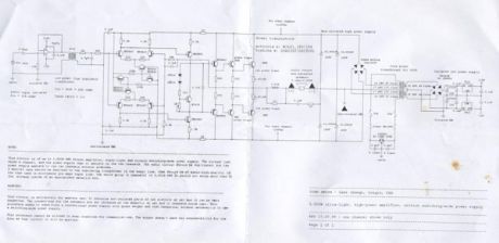
This circuit is of an 2x 2,500W RMS stereo amplifier, super-light and without switching-mode power supply. The circuit just shows a channel, and the power supply that it assists to the two channels. The audio circuit should be duplicated, but the power supply assists to the two channels without problems.
A special care should be destined to the insulating transformer of the audio line, that should be of audio-high-quality, of the type used in microphone pre amps input line. The whole group (2 channels) of 5,000W RMS it should not weigh more than 32 lbs, already inside of an appropriate metallic box. (View)
View full Circuit Diagram | Comments | Reading(1598)
150W MP3 car amplifier
Published:2012/10/12 22:29:00 Author:muriel | Keyword: 150W, MP3, car amplifier
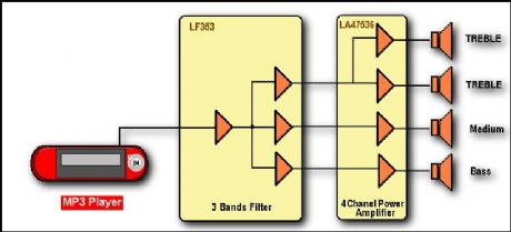
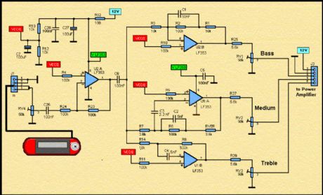
Here, it is a diagramm of an active loudspeaker. The LF353 of, National Semiconductor, is going to split audio signal into three bands. SANYO'S LA47536 is going to amplify these signals. In stereo mode, we shall have the action of eight high speakers who are going to create a very important sound pressure.
Three Band Active Tone Control:
LF353 Wide Bandwidth Dual JFET Input Operational Amplifier General Description These devices are low cost, high speed, dual JFET input operational amplifiers with an internally trimmed input offset voltage (BI-FET II technology). They require low supply current yet maintain a large gain band width product and fast slew rate. In addition, well matched high voltage JFET input devices provide very low input bias and offset currents. The LF353 is pin compatible with the standard LM1558 allowing designers to immediately upgrade e the overall performance of existing LM1558 and LM358 designs. These amplifiers may be used in applications such as high speed integrators, fast D/A converters, sample and hold circuits and many other circuits requiring low input offset voltage, low input bias current, high input impedance, high slew rate and wide bandwidth. The devices also exhibit low noise and offset voltage drift. (National Semiconductor) (View)
View full Circuit Diagram | Comments | Reading(1573)
| Pages:303/2234 At 20301302303304305306307308309310311312313314315316317318319320Under 20 |
Circuit Categories
power supply circuit
Amplifier Circuit
Basic Circuit
LED and Light Circuit
Sensor Circuit
Signal Processing
Electrical Equipment Circuit
Control Circuit
Remote Control Circuit
A/D-D/A Converter Circuit
Audio Circuit
Measuring and Test Circuit
Communication Circuit
Computer-Related Circuit
555 Circuit
Automotive Circuit
Repairing Circuit