
Circuit Diagram
Index 317
The typical application circuit of digital output - angle sensor signal conditioner UZZ9001
Published:2012/9/26 21:27:00 Author:Ecco | Keyword: typical application , digital, output - angle sensor , signal conditioner
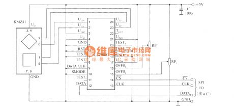
The UZZ9001 typical application circuit is shown in figure. C is the decoupling capacitor. SPI input / output interfaces can be directly matched with the microcontroller (μC), it uses single-chip to set UZZ9001. UZZ9001 measuring angle error is about ± 0.35°.
(View)
View full Circuit Diagram | Comments | Reading(1192)
The bus structure layout of low-power programmable sensor signal processor TSS400-S2
Published:2012/9/26 21:52:00 Author:Ecco | Keyword: bus structure layout , low-power programmable sensor, signal processor
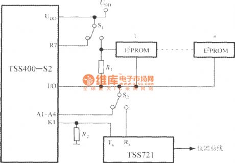
TSS400-S2 bus system allows one-way communication in a two-wire bus. The bus can use twisted pair. Under the request of host machine, the data can be transmitted from slave to host machine. When the bus is effective, the slave machine can start asynchronous data transmission. TSS400-S2's bus structure layout is shown in Fig. This circuit uses a Bus Interface circuit TSS721. It uses ENBUS instruction to complete the slave module remote reading.
(View)
View full Circuit Diagram | Comments | Reading(1006)
The interface circuit between 5-channel low-power programmable sensor signal processor AD7714 and DSP
Published:2012/9/26 22:25:00 Author:Ecco | Keyword: interface , 5-channel , low-power programmable sensor , signal processor, DSP
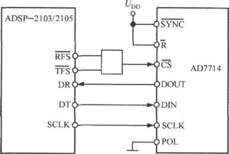
ADSP-2103 or ADSP-2105 is the digital signal processor produced by ADI. The interface circuit between AD7714 and ADSP-2103/2105 is shown as the chart. If ADSP-2103/2105 RFS non-end and TES non- end are configured as low level, the output is effective, then SCLK end is configured as serial clock output. The AD7714 's POL termination is connected to low level. In order to ensure that the AD7714 can work normally, ADSP-2103/2105 serial clock frequency should be limited to less than 3MHz.
(View)
View full Circuit Diagram | Comments | Reading(835)
50 Hz Pulse Generator circuit
Published:2012/9/26 21:37:00 Author:muriel | Keyword: 50 Hz, Pulse Generator
Here is a Crystal based pulse generator that gives 50Hz clock pulses from its output. This circuit can be used as the front end of circuits that require precision 50Hz pulses.The circuit uses two counter ICs CD4060 and CD 4017 to divide the basic frequency to generate 50 Hz pulses. CD4060 is the ripple free binary counter IC and its basic frequency is controlled by a crystal connected in its pin 10 and 11. A 4.9152 MHz crystal is used in the circuit to generate clock pulses. CD4060 divides the 4.9152 crystal frequency by 16,384 so that from the Q13 (output pin 3) 300 Hz clock pulses available.
These clock pulses are then fed into the clock input pin14 of CD4017. It is the Johnson decade counter that divides the 300Hz pulses into 50 Hz pulses which are available from its Q5 (pin1) output.
50Hz Pulse Generator Circuit Diagram
(View)
View full Circuit Diagram | Comments | Reading(1274)
Magnetic Field Sensor circuit
Published:2012/9/26 21:37:00 Author:muriel | Keyword: Magnetic, Field Sensor

This DIY magnetic field sensor circuit is very simple and can detect fixed magnetic fields or fields that are varying at an audio frequency. The unit is not intended to provide accurate measurement of magnetic field strength.
A small and not very powerfull bar magnet can be detected at about 100 mm from the sensor. It has a Hall Effect sensor (UGN3503U) and IC2 (OP77GP or TL071CP), a precision opamp which is used to provide some additional amplification. Meter ME1 is connected between the output of IC2 and the potential divider and it therefore responds to the voltage difference between the two. If audio rather than DC performance is of most importance it would be advisable to use TL071CP for IC2 and then reduce the output resistor from 33k to 27k.
A 6V battery supplies power to the magnetic field sensor circuit and the current consumption is only about 9mA. Do no use a 9V battery as this will result in the maximum supply voltage rating of IC1 being exceeded.
DIY Magnetic Field Sensor Circuit Diagram
(View)
View full Circuit Diagram | Comments | Reading(4124)
FM Radio Receiver circuit
Published:2012/9/26 21:35:00 Author:muriel | Keyword: FM, Radio Receiver
This simple fm radio receiver circuit consists of a regenerative rf stage, TR1, followed by a two of three-stage audio amplifier, TR2 to TR4. In some areas 3 stages of audio amplification may not be necessary, in which case TR3 and its associated components can be omitted and the free end of capacitor C5 connected to the collector of TR2. The critical part of the fm radio receiver is the first stage, TR1/VC1, where the wirings must be kept as short as possible. Coil L1 is formed by winding 8 turns of 1mm (20 swg) enamelled copper wire on a 6 mm diameter former, which is then removed. After that L1 should be stretched carefully and evenly to a length of about 13mm.
FM Radio Circuit Diagram
Transistors ListTR1 = BF199TR2 = TR3 = TR4 = BC547
Video presentation and photos of the working receiver
by Aleksandar
(View)
View full Circuit Diagram | Comments | Reading(949)
Processor Fan Controller circuit
Published:2012/9/26 21:35:00 Author:muriel | Keyword: Processor, Fan, Controller

This Processor Fan Control circuit is intended to be used with relatively old PCs, since more recent models generally have a fan control circuit already integrated into the motherboard. These controllers ensure that the amount of cooling is increased if the processor becomes too warm and decreased if the processor temperature is relatively low. The circuit described here consists of only a handful of components, which you will probably already have in a drawer some-where. Transistors T1 and T2 are driven into conduction by the base current ?owing to the fan via P1 and D1. There will always be a current ?owing through R1, and it will be approximately 120 times as large as the current through R2. R3 has been added to prevent the base current of T2 from becoming too large when P2 is set to its minimum resistance. D1 ensures that even at this extreme setting, the voltage on the base-emitter junction of T3 will still be large enough to allow it to conduct.
Processor Fan Control Diagram
(View)
View full Circuit Diagram | Comments | Reading(2248)
Flashing Light Circuit
Published:2012/9/26 21:35:00 Author:muriel | Keyword: Flashing Light
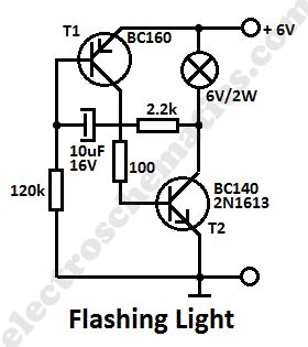
This simple flashing light circuit is powered with 6 volts/0.5A and has a low current consumption when the light bulb is off. The flashing frequency is set by only one capacitor. Transistor T1 may be replaced with BC160 and T2 with BC140.
Simple Flashing Light Circuit Diagram
(View)
View full Circuit Diagram | Comments | Reading(2352)
Electronic Mosquito Repellent circuit
Published:2012/9/26 21:34:00 Author:muriel | Keyword: Electronic, Mosquito Repellent

This electronic mosquitoes repellent circuit is easy to build but is kind of hard to adjust on the exact sound frequency which will reppel the mosquitoes. With frequencies between 2 KHz and 2.5 KHz which mimic male mosquitoes buzz, it seems you can get the best effect.
Mosquitoes Repellent Circuit Diagram
(View)
View full Circuit Diagram | Comments | Reading(1357)
Precise FM Tuning Indicator
Published:2012/9/26 21:33:00 Author:muriel | Keyword: Precise FM, Tuning Indicator
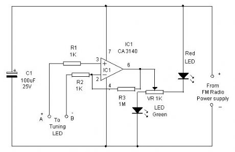
Here is an add on circuit to your FM radio for precise tuning of stations. Usually an LED indicator is provided in FM radio to see whether the station is tuned or not. But it is difficult to see the precise tuning points since the variation in the LED brightness cannot be detected easily. This circuit solves the problem.The circuit uses the Op Amp IC CA3140 as a differential amplifier to sense the voltage level between the terminals of the tuning LED. The output of IC1 drives two LEDs one Red and one Green to indicate whether the station is precisely tuned or not. If both LEDs remain off, it indicates precise tuning. If anyone LED is on, it indicates that tuning is not precise. If both LEDs remain on, it indicates that there is no signal.
Precise FM tuner Circuit
(View)
View full Circuit Diagram | Comments | Reading(1335)
12 Volts Transformerless Power Supply
Published:2012/9/26 21:24:00 Author:muriel | Keyword: 12 Volts, Transformerless, Power Supply

This 12 Volts transformerless power supply take advantage of the fact that a Zener diode is also a normal diode that conducts current in the forward direction. During one half wave, the current ?ows via D1 through the load and back via D4, while during the other half wave it ?ows via D3 and D2. Bear in mind that with this circuit (and with the bridge rectifier version), the zero voltage reference of the DC voltage is not directly connected to the neutral line of the 230-V circuit.
Transformerless Supply Circuit Schematic
(View)
View full Circuit Diagram | Comments | Reading(1673)
5V Switch-Mode Power Supply circuit
Published:2012/9/26 21:24:00 Author:muriel | Keyword: 5V, Switch-Mode, Power Supply
This 5 volts Switch Mode Power Supply circuit use the IC from National Semiconductor has been producing and designing ICs for use in switch-mode power supplies for many years. The application of these devices is normally straightforward, helped by the excellent documentation that is available. A typical example of a switch-mode power supply is that based on the LM2671 or LM2674.The components for it are available for outputs of 3.3 V, 5 V and 12 V. There is also a version providing a presettable output voltage. Within the specified application, the supplies can deliver currents of up to 500 mA. Note-worthy is the high switching frequency of 260 kHz.
This has the advantage that only low-value inductor and capacitors are needed, and this results in excellent efficiency and small dimensions. In normal circumstances, the efficiency is 90% and may even go up to 96%. Both ICs provide protection against current and temperature overloads.
The LM2671 has a number of additional facilities such as soft start and the option to work with an external clock. The latter enables several supplies to be synchronized so as to give better control of any EMC (ElectroMagnetic Compatibility). The application shown in the diagram provides an output voltage of 5 V and an output current of up to 500 mA. Diode D1 is a Schottky type ((Uco≥ 45 V and Imax≥ 3 A).
5 volts switch mode power supply
(View)
View full Circuit Diagram | Comments | Reading(1274)
Sound Generator: The Old West Sounds
Published:2012/9/26 21:21:00 Author:muriel | Keyword: Sound Generator
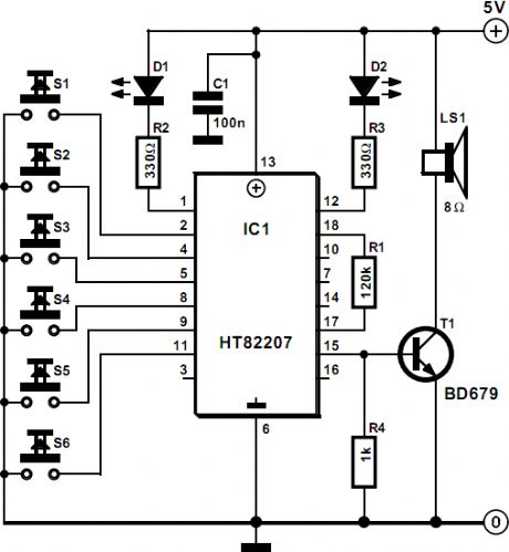
This sound generator circuit will produce 6 sound effects from the old west and it shows how far integration can be taken: IC1, a Type HT82207 from Holtek does virtually everything. Only a (small) loudspeaker and the necessary selectors need to be added.The standard 18-pin Type HT82207 is an integrated sound generator, producing sounds typical of the Old West. The various sounds are selected by S1 – S6 as listed below. In the quiescent state, the circuit draws a current not exceeding 1 μA. (View)
View full Circuit Diagram | Comments | Reading(1761)
Audio Clipping Indicator
Published:2012/9/26 21:18:00 Author:muriel | Keyword: Audio Clipping, Indicator
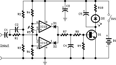
This Audio Clipping Indicator circuit was intended to detect clipping in preamp stages, mixers, amplifiers etc. and can be used as a separate, portable unit, to signal by means of a LED when the output wave form of a particular audio stage is “clipping” i.e. is reaching the onset of its maximum permitted peak-to-peak voltage value before an overload is occurring. This will help the operator in preventing severe, audible distortion to be generated through the audio equipment chain.This unit is particularly useful in signaling overload of the input stages in mixers, PA or musical instruments amplification chains, but is also suited to power amplifiers. A careful setting of Trimmer R5 will allow triggering of the LED with a wide range of peak-to-peak input voltages, in order to suit different requirements.
Unfortunately, an oscilloscope and a sine wave frequency generator are required to accurately setup this circuit. Obviously, the unit can be embedded into an existing mixer, preamp or power amplifier, and powered by the internal supply rails in the 9 – 30V range. The power supply can also be obtained from higher voltage rails provided suitable R/C cells are inserted. SW1 and B1 must obviously be omitted.
Clipping Indicator circuit diagram
(View)
View full Circuit Diagram | Comments | Reading(1766)
Safe 12V Car Adapter circuit
Published:2012/9/26 21:17:00 Author:muriel | Keyword: 12V, Car Adapter
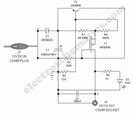
Safe 12V car adapter described here can be used to limit a +12 volt car battery current, available from the in-dash cigar lighter power port, to below 2.6 Amperes for use with portable electronic gadgets and travel chargers on long car journeys. This circuit will protect the car electric system against possible short circuits across the cigar power port.The 12 volts car adapter circuit is connected to the car +12V electric system via the cigar lighter plug J1. The +12V arrives on the board via a reverse voltage protection diode D1. Capacitor C1 decouples the input to the circuit. The current limited 12V output can be taken from the cigar lighter socket J2.Red LED (D2) is a simple power status indicator. After construction,boxed up the unit using a suitable ABS enclosure.
Working of this electronic fuse is very simple. Usually,the mosfet switch T1 is driven via resitor R2 and the 12V from the car battery is available at the output jack J2. The current flow through sense resistor R1 produces a voltage drop,which is at a certain level will force transistor T2 to switch on. This in turn switches off T1 somewhat and the output supply current to the connected electrical load is reduced to prevent costly disasters.
Note: Use a good quality heatsink for T1. Only for cars with negative ground only!
12 volts car adapter circuit diagram
(View)
View full Circuit Diagram | Comments | Reading(1577)
InfraRed Remote Control Tester
Published:2012/9/26 21:17:00 Author:muriel | Keyword: InfraRed, Remote Control, Tester
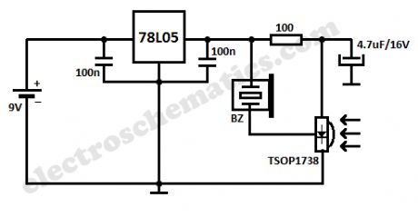
This small InfraRed Remote Control Tester circuit is used for checking the operation of an infrared remote control unit. The circuit is based on the idea of connecting a piezo buzzer directly to an IR receiver IC.Operation of the remote control is indicated by the buzzer making a chattering noise. The circuit is very sensitive and has a range of several metres.The TSOP1738 integrated IR receiver accepts, amplifies and demodulates the IR signal from the remote control, producing an output with a frequency of around 700 Hz. The piezo buzzer is connected to its output, rendering the signal audible. All the other components are simply concerned with producing a stable 5 V power supply from the 9 V PP3-(6F22) type battery.
Instead of the TSOP1738 similar devices from other manufacturers can be used, and of course carrier frequencies other than 38 kHz can be used. The circuit still works if there is a mismatch between the nominal carrier frequencies of the transmitter and receiver IC, but range is reduced. It is still, however, adequate for determining whether a remote control is producing an IR signal or not.
IR Remote Tester Circuit Diagram
(View)
View full Circuit Diagram | Comments | Reading(0)
Flame Failure Monitor
Published:2012/9/26 21:16:00 Author:muriel | Keyword: Flame Failure, Monitor
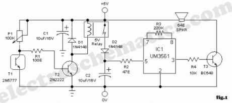

A minimum amount of hardware is needed to build a simple flame or fire failure monitor that enables you to monitor the status of the flame in a chamber/furnace. Owing to its integrated alarm generator, the interface can be easily adapted for use with a wide range of light/heat sensors. Here a readily available photo transistor 2N5777 (T1) works as the flame sensor. The 5V regulated dc supply for this circuit can be derived from a 12 V mains adaptor or a 9V rechargeable battery. In the presence of the flame, T1 conducts (resistance low) and most of the base current of relay driver transistor T2 find an alternative easy path via T1. As a result T2 remains cutoff. If flame is absent, T1 behaves almost an open circuit, and the current through P1 and R1 flows into the transistor’s (T2) base.
Next, the 5V reed relay is energised and 5V positive supply is extended to the alarm generator circuit built around the siren generator UM3561(IC1). Output signals from IC1 is amplified by transistor T2 to drive a standard 64 Ohm 1W mylar speaker.
For optimum perfomance, enclose phototransistor (T1) in a suitable long tube and add an optical assembly (see fig.2). The adjustment of sensitivity set preset pot P1 is also very critical.
Flame (fire) Monitor Circuit Diagram
(View)
View full Circuit Diagram | Comments | Reading(1233)
Sound Controlled Toggle Switch
Published:2012/9/26 21:16:00 Author:muriel | Keyword: Sound Controlled, Toggle Switch
Here is a simple toggle switch that can be operated through sound signals such as whistle or clap. The output of the toggle remains either low or high until the microphone senses the next sound signal. The circuit is too sensitive and can be used to control AC loads through the relay.The sound signal received by the condenser mic will be amplified by IC1. TL071 is the high gain Operational Amplifier used in the preamplifier section of radio and tape recorder. The amplified output is used to control the JK Flip Flop IC CD4027 designed in the toggle mode. When the clock input pin 14 of IC2 gets a low to high pulse from IC1, its output turns high and remains as such. When the next pulse arrives, the output of IC2 turns low. In this way it functions as a toggle switch. Variable resistor VR adjusts the sensitivity of MIC at the particular sound level. Relay driver T1 can be used to operate the relay.
Sound Controlled Toggle Switch
(View)
View full Circuit Diagram | Comments | Reading(717)
The proximity switch circuit with integrated magnetic field sensor HMC1001
Published:2012/9/25 21:25:00 Author:Ecco | Keyword: proximity switch , integrated , magnetic field, sensor
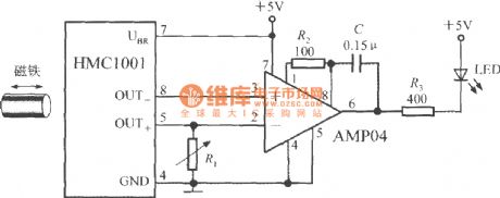
As shown in figure, the proximity switch circuit is composed of HMC1001, operational amplifier (AMP04) and light emitting diode (LED). The operational amplifier is used as a comparator. When you move magnet with length being 6mm~12mm to HMC1001 in a predetermined position, the output voltage of MR bridge will reach 30mV, then the comparator flips, and output becomes a low level to light LED. If the magnet is removed, the comparator outputs high level to turn off LED. Obviously, the circuit is equivalent to the proximity switch of indicator light, and it can be used to detect displacement, rotate speed and other non-electricity. Adjusting R1 can set the threshold voltage of the switch.
(View)
View full Circuit Diagram | Comments | Reading(2375)
The interface circuit of pressure transmitter ( wideband strain signal conditioner 1B31)
Published:2012/9/25 21:35:00 Author:Ecco | Keyword: interface , pressure transmitter , wideband, strain signal , conditioner
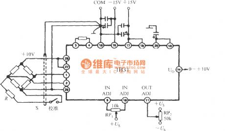
The interface circuit between typical pressure transmitter ( such as Dynisco's 800 series of pressure transmitter ) and 1B31 is shown as the figure. 1B31 outputs +10 V excitation voltage, the pressure transmitter outputs 30mV voltage in full scale. The gain of 1B31 is set 333.3 times to convert the 0 to 10,000 pounds / inch 2 pressure into 0 ~ 10V output. In order to eliminate ground loop, the signal return side and shielded cable must be grounded in the same place. S is the calibration switch, R is the branch calibration resistor to calibrate 80 % of full-scale output point.
(View)
View full Circuit Diagram | Comments | Reading(1545)
| Pages:317/2234 At 20301302303304305306307308309310311312313314315316317318319320Under 20 |
Circuit Categories
power supply circuit
Amplifier Circuit
Basic Circuit
LED and Light Circuit
Sensor Circuit
Signal Processing
Electrical Equipment Circuit
Control Circuit
Remote Control Circuit
A/D-D/A Converter Circuit
Audio Circuit
Measuring and Test Circuit
Communication Circuit
Computer-Related Circuit
555 Circuit
Automotive Circuit
Repairing Circuit