
Circuit Diagram
Index 313
Crystal Controlled 38 kHz IR Transmitter
Published:2012/10/8 2:35:00 Author:muriel | Keyword: Crystal,38 kHz, IR Transmitter
This is a precision 38 kHz Infrared transmitter using MOS integrated circuit uPD 6121.It uses the NEC transmission format ideally suited for remote operation in TV, VCD Player etc. The NEC transmission format includes leader codes, custom codes (16 bits), and data codes (16 bits).The frequency of oscillation is determined by the Crystal. The IR LEDs connected to the output emits IR pulses at 38kHz.The circuit is ideal for most IR Sensors since these are designed for 38 kHz pulsed IR rays. The circuit uses IC uPD6121. It is a CMOS version designed for IR transmission. It operates between 2 and 3.3 volts DC and maximum current consumption is 1 uA. It is a 20 pin IC.
Data codes of IC uPD 6121.
32 Codes single inputs, 3 Codes double inputs, expandable up to 64codes through SEL pin (pin7).Details of Pin connections are shown in the data sheet.
Crystal is connected between the OSCO (Pin8)and OSC1 (Pin9). Output drives a medium power NPN transistor T1 and the IR LEDs connected to its emitter gives pulsed IR rays
Crystal Controlled 38 kHz IR Transmitter Circuit
IC uPD 6121 Datasheet
IR Diodes and Crystal
(View)
View full Circuit Diagram | Comments | Reading(1095)
Servo Motor Controller
Published:2012/10/8 2:34:00 Author:muriel | Keyword: Servo Motor, Controller
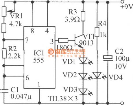
This is the simple basic design of Servo pulse generator. It uses the CMOS IC 7555 in the Astable mode to generate pulses to drive the servo motor. The circuit can be suitably modified to get pulses of sufficient length.A Servo is a small device that has an output shaft. This shaft can be positioned to specific angular positions by sending the servo a coded signal. As long as the coded signal exists on the input line, the servo will maintain the angular position of the shaft. The angular position of the shaft is determined by the duration of a pulse that is applied to the control wire. This is called Pulse Coded Modulation.
The servo typically requires pulse every 20 milliseconds (.02 seconds). The length of the pulse will determine how far the motor turns. Generally, 1.5 millisecond pulse will make the motor turn to the 90 degree position. This is called the Neutral Position. If the pulse is shorter than 1.5 ms, the motor will turn the shaft to close to 0 degrees. If the pulse is longer than 1.5ms, the shaft turns closer to 180 degrees.
Servo Motor Controller Circuit diagram
The circuit is designed to give control signals to the Servo.IC1 is designed as an Astable multi vibrator which can give pulses for the operation of the Servo. The 10KPot VR2, R1 and capacitor C1 determines the High and Low time of pulses. Since VR2 is variable, High time varies from 2.07 mS to 1.03 mS. The low time will be 40.5 mS. By adjusting VR1, it is easy to get exact timing.VR3 adjust the control voltage of 1.6 volts to the control pin 5 of IC1.
Servo Motor
A control voltage can also be supplied from outside. Then VR3 should be omitted. The control volt can be provided from a variable power supply that gives output of 0-10 volts. The control voltage will control the position of the servo motor connected to the output. When the control voltage changes, the servo will move to the new position corresponding to the new control voltage value. 0 volt causes the servo to remain at one end and 10 volts to other end. If the control volt is 5 volts the servo remains in the center position. (View)
View full Circuit Diagram | Comments | Reading(1777)
The counter composed of digital circuit
Published:2012/10/7 21:58:00 Author:Ecco | Keyword: counter , digital circuit
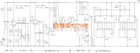
The counter with digital circuit is shown in the figure, and it uses infrared as detection signals, and it can be used for active target scan counting appliances. It is applied to the production line to rapidly and accurately count move items on the conveyor belt. It also can be used for other purposes such as inbound or outbound passenger counting. The characteristics of the circuit is simple structure, easy making, economical and practical use. The most outstanding advantage is that it can accurately count any items with different shade numbers.
(View)
View full Circuit Diagram | Comments | Reading(1264)
The grating circuit using transistor circuit
Published:2012/10/7 21:50:00 Author:Ecco | Keyword: grating, transistor
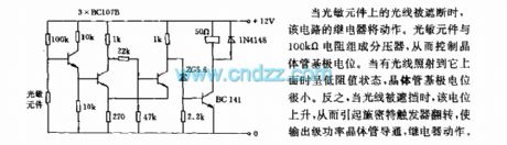
When the light on photosensitive element is interrupted, the circuit's relay operates. The photosensitive element and 100kΩ resistor form a voltage divider, thereby controlling the transistor base potential. When light is exposured to it, it is in a low-resistance state, the transistor base potential is very small. Conversely, when the light is blocked, the potential is increased, thereby causing the Schmitt trigger flip, the output stage power transistor is turned on, then relay operates.
(View)
View full Circuit Diagram | Comments | Reading(1043)
Isolated programmable voltage / current sensor 1B22 used in pressure measurement system
Published:2012/10/7 21:43:00 Author:Ecco | Keyword: Isolated , programmable voltage, current sensor , pressure measurement system
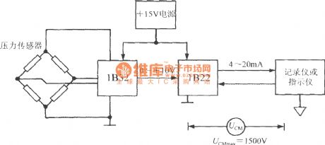
The output signal of pressure sensor 1B32 firstly converted into 0 ~ +10 V voltage signal by bridge sensor signal conditioner, then the 1B22 converts it into 4 ~ 20mA current signal which is finally sent to recorder or indicator. The highest insulation voltage = 1500V ( RMS) UCMmax between public ground of secondary instrument and the power ground of 1B22.
(View)
View full Circuit Diagram | Comments | Reading(1590)
S / R ( set / reset ) pulse generator circuit ( integrated magnetic field sensor HMC1001/1002 )
Published:2012/10/7 21:39:00 Author:Ecco | Keyword: S / R , set , reset, pulse generator, integrated, magnetic field sensor
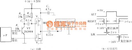
S / R pulse is set / reset pulse, of which amplitude depends on the measurement sensitivity of the MR sensor. For example, Tesla meter is composed of HMC1001/1002, when the minimum measurable flux density is 50nT, the amplitude of pulse current is required not less than 3A; when the minimum measurable flux density is 10 nT, the pulse current amplitude is not less than 4A. The higher measurement sensitivity is, the higher pulse current amplitude is. The circuit uses a microprocessor circuit to generate the S / R pulse, and the circuit is shown as the figure. This circuit uses +16 ~ +20 V power supply, and the pulse current can be more than 4A.
(View)
View full Circuit Diagram | Comments | Reading(2850)
Unipolar mode temperature compensation circuit with linear output integrated magnetic field sensor AD22151
Published:2012/10/7 21:28:00 Author:Ecco | Keyword: Unipolar mode, temperature compensation, linear output , integrated, magnetic field sensor
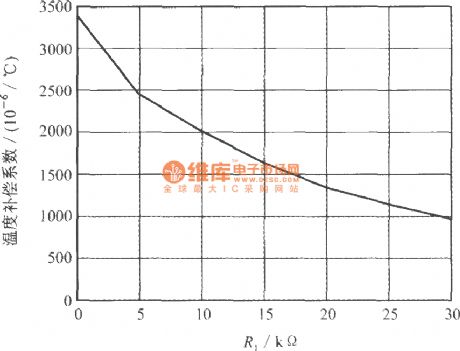
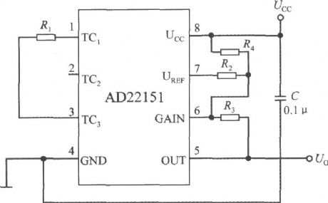
The feature is that R1 is connected between the TC1 end and TC3 end, so that the potential of magnetic null point is not equal to UCC / 2 to compensate for the high temperature coefficient below -2000 × 10-6/ ℃. When TC2 end is open, the compensating resistor R1 and internal resistor RB form the temperature compensation coefficient voltage divider. Under unipolar mode, the relationship curve between R1 resistance value and temperature compensation coefficient is shown as below.
(View)
View full Circuit Diagram | Comments | Reading(2422)
Cold Sensor Circuit
Published:2012/10/7 21:15:00 Author:muriel | Keyword: Cold Sensor
This circuit monitors the temperature level in Air-conditioned rooms, Labs, Cold storage etc. and intimate you whether the low temperature is maintained in the room or not. It gives audio visual indications when the Air-conditioning system or freezing system fails and temperature rises. This prevents the spoilage of stored materials. If the temperature is above the preset level, it gives LED indications first and after Four minutes it gives loud beeps inviting immediate attention.The circuit uses NTC Thermister as temperature sensor. Its resistance decreases when the temperature in its vicinity increases above one degree or more.IC1 is wired as a voltage comparator with its inverting and non inverting inputs tied to two potential dividers. The non inverting input (pin3) receives a variable voltage from the potential divider comprising the NTC Thermister and VR1. Similarly, the inverting input (pin 2) also receives an adjustable voltage from the potential divider R1 and VR2. Preset VR1 adjusts the voltage level at pin 3 slightly lower than that of pin 2 in the idle state in which the room temperature is below 26 degree. VR2 adjusts the voltage level at pin2 of IC1 slightly higher than that of pin 3.
Cold Sensor Circuit diagram
Errata : Pin 8 of IC CD4060 is ground. It should be connected to negative rail.
Normally IC1 will give Zero volt output since its pin3 gets lower voltage than pin2.This is due to high resistance of Thermister in cold. When the Refrigeration system fails, room temperature rises above 30 degree and the resistance of Thermister decreases. This allows more current to flow into pin 3 and output of IC1 becomes high. This triggers T1 and Yellow LED turns on indicating that the room temperature is rising. If this condition persists, T1 remains conducting and the reset pin 12 of IC2 reach the ground potential and the IC2 starts oscillating. With the given values of C1 and R5, Q8 output becomes high after 2 minutes. This makes the Red LED flashing. If the condition continues, Q9 output becomes high after 4 minutes and buzzer starts beeping. In short, if the refrigeration system is not restarted within 4 minutes buzzer beeps to invite the attention.
NTC Thermister and IC CD4060
(View)
View full Circuit Diagram | Comments | Reading(1640)
The high power control circuit with 3 different driving ways
Published:2012/9/28 22:51:00 Author:Ecco | Keyword: high power, control circuit, 3 , different driving ways
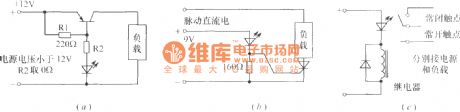
Flashing light-emitting diode can be used as the core component of high-power multi- load control circuit to drive various incandescent flashing lights. Figure (a) shows a high - power transistor driving circuit; Figure (b) shows a bidirectional thyristor-controlled with high-power drive circuit ; The circuit shown in Figure (C) uses a relay to control load. VT can use 3AD, 3CD high power PNP transistor. Transistor can also use one - way , but the load current is the pulsating DC current. The loads of 3 kinds of circuits can intermittently work under the control of flashing light-emitting diode.
(View)
View full Circuit Diagram | Comments | Reading(1078)
High voltage regulator circuit with optocoupler
Published:2012/9/28 22:37:00 Author:Ecco | Keyword: High voltage, regulator, optocoupler
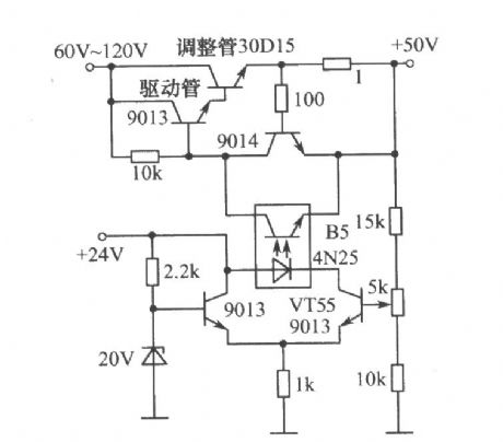
The circuit is shown as the figure. Usually, the drive tube needs to use transistor (Figure 9013) with higher withstand. When the output voltage increases, VT55's bias increased, then the forward current of light emitting diode in B5 increases, so that the voltage across poles of photodiodes decreases, the adjustment tube BE junction bias voltage is lowered while the internal resistance increases, so that the output voltage is reduce ; Conversely, the output voltage increases, thereby maintaining the stability of the output voltage.
(View)
View full Circuit Diagram | Comments | Reading(3394)
The typical application circuit of LB140 5-bit LED level indicator driver IC
Published:2012/9/28 22:52:00 Author:Ecco | Keyword: typical application , 5-bit , LED level , indicator, driver IC
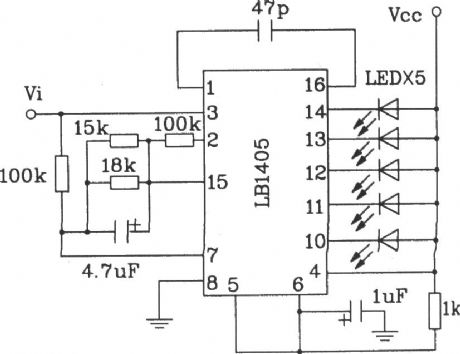
BL1405 is widely used in the recorder and tape recorders for level indication.
(View)
View full Circuit Diagram | Comments | Reading(2857)
The interface circuit composed of optocoupler
Published:2012/9/28 22:28:00 Author:Ecco | Keyword: interface , optocoupler

As shown in figure, the optocoupler 4N25 in circuit plays the role of the the coupled pulse signal and isolation microcontroller 89C51 system and output section, so that the current of two parts is independent from each other. Output portion of the ground wire is connected to the chassis or earth, while the 89C51 system power ground wire is floating, and it is not connected to the ground wire of AC power to avoid the effect from power changes of output on microcontroller power, so it reduces interference the system suffered and increase system reliability.
(View)
View full Circuit Diagram | Comments | Reading(2548)
The application circuit of bridge sensor signal conditioner 1B32 macthed with multi-channel pressure sensor
Published:2012/9/28 21:58:00 Author:Ecco | Keyword: application , bridge sensor ignal conditioner , multi-channel pressure sensor
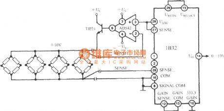
The excitation power can drive multiple bridge sensors after passing AD542 and TIP32. AD542 is the operational amplifier which uses Bi-FET as input stage for the starting buffer. TIP31 is the epitaxial NPN power transistor, and its maximum reverse voltage is 45V, and the maximum collector current is 3A, the maximum power consumption is 40W. The circuit can provide +10 V, 300mA excitation source in the temperature range of -25 ~ +80 ℃. When 1B32's 333.3 GAIN is grounded, the gain is set to 333.3 times.
(View)
View full Circuit Diagram | Comments | Reading(1623)
Panic Alarm Circuit
Published:2012/9/28 21:05:00 Author:muriel | Keyword: Panic Alarm Circuit
Imagine the Panic situation in the Midnight when an intruder tries to break into the house. This Alarm will help you with its loud Police siren to abort the attempt of intrusion. With a single clap, the circuit generates the alarm for three minutes and then goes off. This is sufficient to catch the attention of neighbours.The circuit is a sensitive Clap switch with timer action. IC1 is designed as a sensitive inverting amplifier to amplify the sound signals from the condenser mic. Variable resistor VR1 set the sensitivity of mic and resistor R1 and VR2 set the gain of the amplifier. If the sensitivity of mic and amplifier is suitably adjusted, the circuit can detect the sound from a distance of 5meters or more.
Panic Alarm Circuit Diagram
(View)
View full Circuit Diagram | Comments | Reading(1197)
Portable Power Supply circuit
Published:2012/9/28 21:05:00 Author:muriel | Keyword: Portable, Power Supply
Here is an ideal Power Supply Unit for trouble shooting the circuit boards. It gives Five and Nine volt regulated DC from a Rechargeable battery. It is portable and handy and can also functions as a Mobile Charger. Transformer less power supply is used in the circuit to charge the battery from mains. This makes the unit compact and light weight. The circuit has two sections. The front end is a charger section with capacitor C1 as the main element. It is an X rated 400 Volt AC capacitor that reduce the 230 volt AC to low volt AC through the Rectance property. Low volt AC is then rectified by the full wave bridge rectifier comprising D1 through D4.
Resistor R1 bleeds the stored current from C1 when the power is disconnected. Resistor R2 reduces the inrush current into the circuit at power on. Rectified AC is then made ripple free by C2 for charging the 9 Volt Rechargeable battery. Zener diode ZD regulates the charging voltage to 15 volts and resistors R3 and R4 gives around 80 to 100 mA charging current. Diode D6 prevents discharge of battery back to the bridge.
Variable resistor VR1 and transistor T1 forms a voltage indicator. LED lights when the battery is fully charged and goes off if the battery voltage reduces below 7 volts. VR1 sets the low voltage level. This prevents deep discharge of battery. When the circuit is connected to mains and S1 is in ON position, battery charges through D5, R3, R4 and D6. When the unit is unplugged from mains, 9 volt output power will be available from the battery. Voltage regulator IC1 gives 5 volt DC. Switch S2 can be used to select 9 v or 5v output.
Portable Power Supply Circuit diagram
Note: Connect a fully charged 9 Volt battery and adjust VR1 till the LED light up. During this adjustment, the circuit should be disconnected from the mains. Use the power supply only after disconnecting it from Mains. The 5volt DC from it can be used for charging the Mobile phone. Use a suitable pin for that. Rechargeable battery can be an ordinary PP3 battery or High current NiMh battery.
(View)
View full Circuit Diagram | Comments | Reading(1656)
Cellphone Charger Using Bike Battery
Published:2012/9/28 21:04:00 Author:muriel | Keyword: Cellphone Charger, Bike, Battery
This is the simple and easy way to tap current from a Motor Bike battery to charge the Mobile Phone. Most of the Mobile Phone battery pack has three 1.2 volt cells making the voltage to 3.6 volts. For fast charging of the battery pack, each cell requires more than 1.2 volts and sufficient current. This circuit can deliver 5 volts at 300 mA to charge the battery quickly. The circuit is Voltage and Current regulated and with Polarity and Surge protection components.
Mobile Charger using Bike Battery Circuit Schematic
The circuit uses a Positive Voltage regulator IC 7805 to give 5 volt regulated output. The components around IC1 are meant for protecting the IC so as to give smooth output power. Zener diode ZD act as the Input Surge protecting diode. It provides 7.2 volts to the input of the regulator IC from the 12 volt bike battery. Diode D1 is the Output Surge and Input Short protecting diode.
When a surge voltage exceeding maximum voltage rating of the regulator is applied to the input or when a voltage in excess of the input voltage is applied to the output, the regulator will be destroyed. If the input terminal shorts with the ground, the output voltage increases above the input voltage(ground potential)and the charge in the capacitor connected to the output flows into the input side which is also fatal to the regulator. Both these situations can be avoided by using the Zener at the input and the diode D1 across the regulator. Capacitor C1 and C2 provide stability to the regulator and these should be soldered close to the legs of the regulator. Capacitor C3 act as a buffer to give constant voltage in the output.7805 Datasheet
7805 IC can tolerate maximum 35 volts and its current rating is 1 Amps maximum. Resistor R1 restricts the charging current to around 330 mA as per the Ohms law. Even if the current is low, charging process will not be affected. Slow charging with 80 to 100 mA current is generally advised. But in case of an emergency, quick charging can be done with high current
Assemble the circuit on a Perfboard and enclose in a small case that can be fitted near the Bike battery. Use suitable pins to connect with the Mobile phone. Charging current can be tapped from the battery using Alligator Clips. Before using the circuit, double check the connections especially the polarity of connectors and measure output voltage and current using a Digital Multi Meter. The same circuit can be used for charging Mobile battery from 12 volt Car battery or from a 12 volt Solar panel.
IC 7805 Pin connection and Alligator Clips
(View)
View full Circuit Diagram | Comments | Reading(1320)
Lithium battery cell tester circuit
Published:2012/9/28 21:03:00 Author:muriel | Keyword: Lithium battery cell, tester
3 Volt Lithium Cells are extensively used in low power applications such as Digital clocks, Toys etc. These are also used in Computer Mother boards as backup power source to keep the memory. The circuit described here is a handy tester to check the voltage level in the used Lithium cell before throwing it away.Even if it carries less than 2 volts, it can be used again in some very low power applications that require less than two volts.The circuit uses an LED as a Zener diode to give 2.2 V reference voltage to compare the voltage level in the Lithium cell.IC1 (TL071) is used as a Voltage comparator. The low noise JFET Operational Amplifier TL071 is used in the circuit since it requires very low input bias current. Its inverting input is connected to the junction between R2 and a Green LED. Here LED is used like a Zener diode to give 2.2 V (Forward voltage of Green LED) as reference voltage.This LED has dual function. It act as a power on indicator as well as low value Zener which is not commonly available.
The non inverting input of IC1 receives voltage from the Lithium battery under test. When the non inverting input is not connected to the battery, output of IC1 will be low since its inverting input gets higher voltage than non inverting input. The low output from IC1 keeps T1 non conducting and the Green half of the Bicolour LED remains off.At the same time the high voltage in the collector of T1 gives base bias to T2 and it conducts. The Red half of the bicolour LED lights.
Lithium Cell Tester Circuit diagram
When a Lithium battery is connected to test points, the non inverting input of IC1 gets higher voltage (more than 2.2 volts) and the output of the comparator swings high. This makes T1 conducting and Green half of Bicolour LED lights indicating that the battery under test is holding more than 2.2 volts. At the same time T2 turns off since its base goes to ground potential. Red LED remains off in this state. In short, Green LED lights if the battery holds more than 2.2 volts.
TL071 and BC548 Pin Connections
Lithium battery cell
(View)
View full Circuit Diagram | Comments | Reading(1605)
Automatic Gate Lamp circuit
Published:2012/9/28 21:02:00 Author:muriel | Keyword: Automatic Gate, Lamp
This circuit lights the Premises of House around 6 pm and turns off in the morning. Its working is fully automatic and uses the light sensing property of LDR. Unlike other LDR based circuits, it will not cause lamp flickering during the light transition so that CFL and fluorescent lamps can be used. It also exploits the Schmitt trigger action of timer IC 555 for a clean switching.LDR and timer IC 555 are used in the circuit for automatic switching. Light Dependent Resistor offers very high resistance around 10 Meg ohms in dark but in light it has only 100 ohms or less resistance. So it it is an ideal component to switch on lamps based on the presence or absence of sun light. Here it is used to trigger the timer IC 555 which is designed as a Schmitt trigger.
Schmitt Trigger
The popular Timer IC 555 has two internal comparators. These are Threshold comparator and Trigger comparator. The Set and Reset action of these comparators can be used for On/ Off actions. Here the IC 555 functions as a Bistable with Schmitt trigger action. The upper comparator (Threshold comparator) of IC 555 trips at 2/3 of the supply voltage and the lower comparator(Trigger comparator) trips at 1/3 of the supply voltage. In the circuit, the inputs (pin6 and pin2) of both the comparators are shorted and connected to the junction of LDR and the Preset VR1.
In day light, LDR passes more current and the current into the upper comparator (pin6) is above 2/3 Vcc. This resets the internal Flip-Flop of IC. At the same time, the current into the lower comparator (pin2) is more than 1/3 Vcc. Both these condition causes low output from IC1.
Automatic Gate Lamp Circuit
When the light falling on the LDR decreases, its resistance increases, and the current flowing to the upper and lower comparators of IC1 decreases. The input voltage of upper comparator decreases below 2/3 Vcc and that of lower comparator below 1/3 Vcc. This causes, high output from pin 3 of IC1. This triggers T1 and the relay connected to its collector turns on. The lamp gets AC through the Common and NO (Normally Open) contacts of the relay. Only the Phase line is connected through the relay contacts. The neutral line goes as such.
VR1 adjusts the sensitivity of LDR at the particular light level at which the lamp turns on. Capacitor C2 maintains the base voltage of T1 for clean switching action and also avoids relay clicking. Diode D1 removes back e.m.f when T1 switches off.
IC 555 Internal Circuit
Note: LDR should be placed away from the Lamp light but it should get day light. Use 6 Volt PCB relay. Wiring connections are given in the diagrams.
PCB Relay and Wiring connection
Caution: Take extreme care while connecting AC line to the relay contacts. Do not touch the relay contacts when the circuit is connected to mains. Provide sleevings to relay contacts to avoid accidental shorting.
PCB Relay
(View)
View full Circuit Diagram | Comments | Reading(1680)
Motion detector alarm circuit
Published:2012/9/28 21:02:00 Author:muriel | Keyword: Motion detector, alarm
This motion detector alarm circuit can detect a moving person from a distance of 1 meter. It uses a Dual IR Transmitter-Receiver module HOA1405. When the sensor detects the reflected IR rays, Alarm will sound for 2 minutes. The circuit can be modified for various applications including AC operated alarm systems.
Motion Detector Circuit Schematic
The main element in the motion detector circuit is the Dual IR reflective sensor HOA 1405. It has a built in IR diode and an NPN Photo transistor. The black covering of the module filters visible light rays and allow IR rays to fall on the Photo transistor. When the Photo transistor receives IR rays, it conducts. The collector of the Photo transistor is connected to the trigger pin2 of a short duration Monostable timer built around IC NE 555.
With the given values of R4 and C2, output of IC1 remains high for two minutes to light LED and to activate the buzzer. In the standby state, the photo transistor inside the Dual Reflector module remains non conducting since its base is not getting IR rays. When a person comes in front of the module, the reflected IR rays will trigger the Photo transistor and its Collector goes to ground potential. This triggers the Monostable and Alarm sounds.
IR Dual Reflective Sensors
(View)
View full Circuit Diagram | Comments | Reading(1552)
Three State Voltage Indicator circuit
Published:2012/9/28 21:02:00 Author:muriel | Keyword: Three State, Voltage Indicator
This is an ideal circuit to monitor the Voltage level in 12 volt Lead Acid batteries used in Inverters .For the perfect operation of Inverters, the battery voltage should be between 12 and 13.5 volts. A fully charged battery shows 13.5 volts. If the voltage reduces below 10 volts, the Inverter will not give back up. Moreover, if the Inverter is continuously charging without attaining 13.5 volts, it indicates that the battery is not accepting and holding charge.The circuit is too simple and uses only a few components. It shows three indications.
1. If the battery has 13.5 volts, Green half of the bicolor LED lights.2. If the battery has 12 volts(Normal) LED will be Off3. If the battery voltage reduces below 10 volts, Red half of bicolour LED lights.
About the Semiconductors
The important components of the circuit are a two lead type bicolour LED and the Operational Amplifier CA3140.
Bicolour LED
The Bicolour LED used in the circuit is a Two Lead type. That is, it can give Red or Green lights based on the polarity of the leads. If the leads are connected in one direction, it gives one colour and if the leads are reversed, it gives the second colour. Thus there is no Anode- Cathode arrangement. Both the leads can function as Anode and Cathode. The internal arrangement of the LED automatically changes the direction of current based on the polarity. Here the LED used gives Red and Green colours.
BIcolour LED Datasheet
CA3140This Operational Amplifier is a 4.5 MHz BiMOS Op Amp with gate protected MOSFET inputs and Bipolar output. Its inputs have very high input impedance (1.5T Ohms).It require very low input current (10pA) and hasvery high speed of performance. The IC can operate between 4 – 36 volts with single or dual power supply.CA3140 is internally phase compensated for stable operation
(View)
View full Circuit Diagram | Comments | Reading(881)
| Pages:313/2234 At 20301302303304305306307308309310311312313314315316317318319320Under 20 |
Circuit Categories
power supply circuit
Amplifier Circuit
Basic Circuit
LED and Light Circuit
Sensor Circuit
Signal Processing
Electrical Equipment Circuit
Control Circuit
Remote Control Circuit
A/D-D/A Converter Circuit
Audio Circuit
Measuring and Test Circuit
Communication Circuit
Computer-Related Circuit
555 Circuit
Automotive Circuit
Repairing Circuit