
Circuit Diagram
Index 319
7805 Regulator IC Circuits
Published:2012/9/25 21:33:00 Author:muriel | Keyword: Regulator
Fixed voltage Positive and Negative regulator ICs are used in circuits to give precise regulated voltage.78 XX series regulator IC can handle maximum 1 ampere current. The Regulator ICs require minimum 1.5 higher input voltage than their voltage rating. For example 7805 IC requires minimum 6.5 volts to give 5 volt output. Here are some circuit designs of IC 7805 to monitor the output voltage.1.This is the manipulation of the Regulator IC 7805 to give 9 volt regulated output. Normally the pin2 of the regulator IC is connected to the ground. Here it is connected to a 3.9 volt Zener diode. So the output from the Regulator IC will be 9 volts.
7805 Circuit 12. This circuit can tell whether the IC 7805 is giving output or not. IC 7805 requires minimum 6.5 volt input to give 5 volt regulated output. When the input voltage is above 6.5 volts, Zener conducts and LED turns on indicating sufficient input voltage. Diffuse type Red LED requires 1.8 volts and Zener 4.7 volts .So to activate both these, input voltage should be minimum 6.5 volts. If the input voltage drops below 6.5 volts, Zener cutoff and LED turns off. This indicates the zero output from the regulator IC.
7805 Circuit 2
3. This is a simple LED monitor to tell the output voltage from 7805. If the input voltage is above 6.5 volts, LED shows full brightness. When the input voltage reduces below 6.5 volts, brightness of LED decreases.
7805 Circuit 3
(View)
View full Circuit Diagram | Comments | Reading(992)
PC Watcher | Turn On and you’ll hear the Alarm
Published:2012/9/25 21:32:00 Author:muriel | Keyword: PC Watcher, Alarm circuit
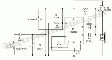
This little PC Watcher circuit will help you to prevent unauthorised access to your personal computer. After construction on a small piece of veroborad, enclose the whole circuit in a tamper proof plastic box and connect its input to a vacant USB port at the rear of your Desktop PC, using a standard USB cable.Now hide the unit in a suitable place. If anyone tries to switch on your PC, the circuit starts beeping to raise an aural-alert. The alarm function can be disabled by flipping the SPST toggle switch S1 to its ON position. The circuit is “self-powered” ie no additional power supply/battery is required!This alarm circuit is designed using the 14-stage ripple counter CD4060 (IC1). When computer starts running, 5 Volt dc available from its USB port is fed to the circuit through polarity protection diode D1. When IC1 gets power from the PC, it resets through C3 and R1 and starts oscillating. Reservoir capacitor C1 maintains the voltage to IC1 stable so that the oscillation is not affected by slight variations in the USB power line, while capacitor C2 suppresses any unwanted high frequency noise.Resistor R2 and capacitor C4 maintain the oscillation of IC1, as indicated by the beeping of piezo-buzzer connected to its output (pins 3&5) through an npn transistor switch T1. With the components values shown, the buzzer beeps intermittently (after an initial delay of 30 secs) for near 30 secs, then stops for the same period of time and the cycle repeats until the input condition is reversed.
PC On Alarm Circuit Schematic
(View)
View full Circuit Diagram | Comments | Reading(986)
Security Light & Switch with PIR Sensor
Published:2012/9/25 21:31:00 Author:muriel | Keyword: Security, Light, Switch, PIR Sensor
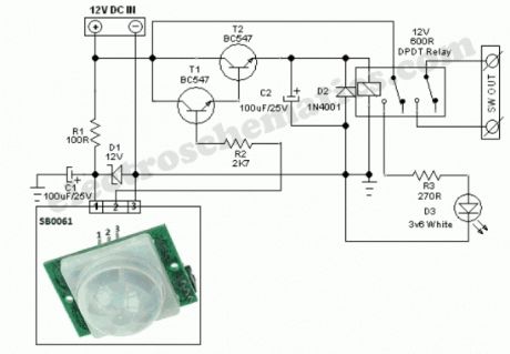
SB0061 is a pyroelectric sensor module,developed for human body detection. A PIR detector combined with a fresnel lens are mounted on a compact size PCB together with an analog IC (SB0061) and limited components to form the module. High level output (3.3V) of pre-settable variable width (5Secs -18 Minutes) is provided.
Circuit diagram of the PIR Motion Sensor Light and Switch based on SB0061 shown here can be used for security or corridor lighting in power saving mode. The 12V DC supply required for the whole circuit can be fed from any standard 12V ac mains adaptor/battery.
Working of the circuit is simple and straight forward. When any movement is detected within near 5-6 metres, around 3.3 Volt is appeared at the base of Transistor T1 and it conducts to fire the next relay driver transistor T2. As a result, the 12V DPDT relay is energised to power the White LED through current limiting resistor R3. Spare relay contacts can be used as a switch to control any suitable external load. The white LED and the relay remains ON for a duration based on the mono time setting in SB0061, ie from 5 Secs to 18 Minutes.
PIR Motion Sensor Circuit Schematic
(View)
View full Circuit Diagram | Comments | Reading(3977)
Pressure Sensor Alarm circuit
Published:2012/9/25 21:30:00 Author:muriel | Keyword: Pressure Sensor, Alarm circuit
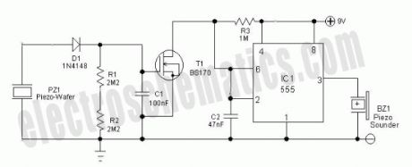
General purpose circuit of the simple pressure sensor alarm is built around a couple of readily available cheap components. Working of this circuit is straight forward and self-explanatory. When the circuit is powered by a 9V compact battery, the active piezo-sounder at the output of IC1 starts beeping for a short time and then goes into idle state.Whenever, the pressure sensor element (Piezo-ceramic wafer) is gently tapped, mosfet T1 is fired by the electric pulse from the sensor through related components and IC1 is again enabled by T1. As a result, the piezo-sounder starts beeping for a short duration, set by the in-circuit values of R3 and C2. Piezo-sounder at the output of IC1 can be replaced with a low current 6 to 9 V electromagnetic/solid-state relay to control external loads. Likewise, values of components T1,R3 and C2 are not very critical.You can experiment with another values to “tune” the circuit as per your requirements. Pressure sensors (in piezo-wafer form) are widely available with reputed hobby electronics components dealers.
Pressure Sensor Alarm Circuit Schematic
(View)
View full Circuit Diagram | Comments | Reading(1477)
Car Interior Light Dimmer
Published:2012/9/25 21:30:00 Author:muriel | Keyword: Car Interior, Light Dimmer
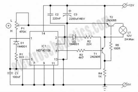
Ultra simple car interior light dimmer circuit of a pulse width modulated (PWM) energy saving dc lamp dimmer is described here. With the help of this circuit, you can control the intensity of the dome lamp in your car from near 5% to 90% using a single potentiometer. The circuit is designed for cars with negative ground.The circuit works off 12V dc supply from the car battery and is capable of driving dc incandescent lamps of wattages up to 24W!The design is based on IC1 (40106) astable multivibrator whose output is low for a period determined by R2 and high for a period determined by R1 and P1. Output from IC1 (at pin4) is applied to the base of transistor T1.Transistors (T1&T2) are switched on and the lamp is energized during the negative period of the output pulse of IC1. When the resistance of P1 is at maximum, the brightness of the lamp is at minimum level.
12V Light Dimmer Circuit Schematic
(View)
View full Circuit Diagram | Comments | Reading(2254)
Simple Touch Alarm circuit
Published:2012/9/25 21:29:00 Author:muriel | Keyword: Touch, Alarm circuit
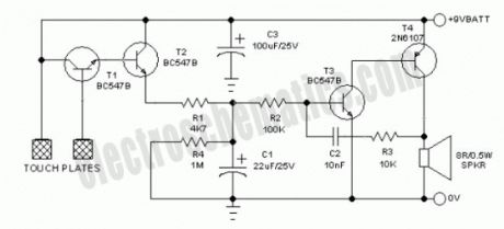
Touch the sensor of the alarm with your finger and it starts beeping, goes on for some time and then stops. Touching it again, and it goes again! This little and flexible circuit consists of a touch sensor and a directly coupled transistor amplifier with a small loudspeaker as the output load. Two sensor strips of metal are mounted side by side on a 1×1 cm size micasheet and connected to the input of the circuit.How the touch alarm works
Under normal conditions no current flows through switching transistors T1 and T2 and the potential across capacitor C1 is almost 0V. If the two touch plates are touched together by a finger, the alarm circuit is enabled by T1 and T2. Transistors T3and T4 form a complimentary pair amplifier, with positive feedback (regeneration) provided to the base of first transistor T3 via R3 and C2.The sound generator oscillates at a frequency determined by C2 and R3 and the bias voltage of T3. The bias voltage of T3 can be changed by changing the values of R2 (and R1). The alarm will provide quite loud audio output into an 8 Ohm speaker with a 9V battery at a current drain of less than 100mA. Needless to say, this is an ultra simple hobby circuit. You can experiment with different component values (R1,R2,C1,C2,R3 and R4, etc) to make your own special alarm!
Touch Alarm Circuit Schematic
(View)
View full Circuit Diagram | Comments | Reading(1693)
Photodiode Alarm circuit
Published:2012/9/25 21:28:00 Author:muriel | Keyword: Photodiode, Alarm circuit
This Photodiode based Alarm can be used to give a warning alarm when someone passes through a protected area. The circuit is kept standby through a laser beam or IR beam focused on to the Photodiode. When the beam path breaks, alarm will be triggered.
The circuit uses a PN Photodiode in the reverse bias mode to detect light intensity. In the presence of Laser / IR rays, the Photodiode conducts and provides base bias to T1. The NPN transistor T1 conducts and takes the reset pin 4 of IC1 to ground potential. IC1 is wired as an Astable oscillator using the components R3, VR1 and C3. The Astable operates only when its resent pin becomes high. When the Laser / IR beam breaks, current thorough the Photodiode ceases and T1 turns off. The collector voltage of T1 then goes high and enables IC1. The output pulses from IC1 drives the speaker and alarm tone will be generated.
Photodiode Alarm Circuit
IR Transmitter Circuit
(View)
View full Circuit Diagram | Comments | Reading(832)
Simple 12 Volt Charger circuit
Published:2012/9/25 21:27:00 Author:muriel | Keyword: 12 Volt, Charger
This is the circuit of a simple 12 volt battery charger for Lead Acid battery. It gives 12 volt and 5 Amps current for quick charging of the battery. If the battery is partially discharged, full charge will be attained in one hour.The circuit uses a 0-14 volt 5 Ampere Step down transformer and a 10 Amps Bridge rectifier module to convert AC to DC. Since pulsed DC is good for Lead Acid battery, a low value smoothing capacitor is used as C1.To monitor the charging status, Ampere meter is provided in the positive rail. LED act as the Charger on status.
Simple 12 Volt Battery Charger Circuit
When the output is connected to the battery terminals, the meter shows a higher reading depending on the current flow into the battery. As the battery attains full charge, its terminal voltage rises to 13.8 volts and current through the meter ceases. The meter reading then returns to zero. This indicates the full charge state and the charging can be terminated. (View)
View full Circuit Diagram | Comments | Reading(1389)
Charger On Demand
Published:2012/9/25 21:27:00 Author:muriel | Keyword: Charger
This Automatic Battery charger turns On only when the battery demands charging current. It can be used to charge 12 Volt Lead Acid or Tubular batteries .The automatic switching helps to keep the battery always in top condition. The overcharge and over discharge cut off facilities are included so that the charger can be left unattended for long periods.
The switching action through the relay is achieved by by sensing the terminal voltage of the battery under charge. Relay contacts break the AC supply to the charger transformer when the battery voltage rises above 14 volts. When the terminal voltage drops below 11.5 volts, relay contacts complete the Neutral path of AC supply to the charger transformer.
Operational Amplifier IC1 is used as a precision voltage comparator to monitor the voltage level of the battery. Its Inverting input gets a reference voltage of 1.8 V from the junction of Red LED and R3 while the Non inverting input gets slightly higher voltage of 2 volts ( as set by VR1). This makes output of IC1 high. PNP transistor then remains off to keep the relay de-energized. Since the Neutral line is connected through the Comm and NO contacts of the relay, AC path remains cut off and no charging takes place.
When the battery voltage drops below 11.5 volts, voltage at the Non inverting input (pin3) drops below that of the Inverting input (pin2) and the output of IC1 turns low. T1 then conducts to actuate the relay. Relay contacts completes the neutral path and charging process starts. Green LED indicates the charging process.
Charger On Demand Circuit
(View)
View full Circuit Diagram | Comments | Reading(1112)
Day Charger circuit
Published:2012/9/25 21:27:00 Author:muriel | Keyword: Day, Charger
This LDR controlled Adjustable charger can be used to charge the Rechargeable battery of portable devices. It charges the battery only during day time. This saves energy and prevents overcharging of the battery. The output voltage from the charger varies from 6 – 12 volts which can be adjusted. Current flow depends on the ambient light in the room.Charging current is obtained from a 0-12 volt 500 mA step-down transformer, a full wave rectifier D1through D4 and smoothing capacitor C1. LED indicates the power on status. LDR is used as a light sensitive switch for controlling the charging process. During day time, LDR offers less resistance and provides sufficient base bias to T1. When T1 conducts, output will be available from the emitter of T1.Pot VR1 controls the output voltage. Current flow depends on the resistance of LDR which in turn depends on the light falling on LDR. In bright day light, resistance of LDR reduces to 100 K or less and more current flows into the base of T1. When the LDR is in dark, its resistance increases to 10 Meg Ohm and prevents the base current to T1. T1 then turns off and output ceases.
Day Charger Circuit
Note: Keep the LDR / charger in a place where day light is available. Adjust VR1 till sufficient output voltage is obtained. Measure the output using a multimeter. Output current can be between 50 mA to 300 mA depending on the illumination. If continuous charging is required, replace LDR with a 470 ohms resistor.
(View)
View full Circuit Diagram | Comments | Reading(683)
Simple Battery Monitor circuit
Published:2012/9/25 21:25:00 Author:muriel | Keyword: Battery Monitor
This simple Battery Monitor lights an LED when the battery voltage drops below 9 volts. It is an ideal add on circuit to monitor the charge level in 12 volt miniature batteries used in Portable devices or Alarm systems. In the standby state, LED remains off.Working of the circuit is based on the base biasing of transistor T1. When the battery voltage is above 9 volts, base-emitter voltage will be same. This keeps both T1 and LED off. When the battery voltage reduces below 9 volts due to consumption, base voltage of T1 drops while its emitter voltage remains same since capacitor C1 is fully charged. At this stage, base of T1 becomes positive and T1 turns on. Capacitor C1 discharges through the LED and it lights.
Simple Battery Monitor Circuit
(View)
View full Circuit Diagram | Comments | Reading(842)
PC Heat Monitor Circuit
Published:2012/9/25 21:25:00 Author:muriel | Keyword: PC,Heat Monitor
The PC processor generates very high temperature during its operation which is dissipated by the large heat sink placed above the processor. If the heat sink assembly is not tight with the processor or the cooling fan is not working, PC enters into the Thermal shutdown mode and will not boot up. If the PC is not entering into thermal shutdown, the high temperature can destroy the processor. This simple circuit can be placed inside the PC to monitor the temperature near the processor. It gives warning beeps when the temperature near the heat sink increases abnormally. This helps to shutdown the PC immediately before it enters into Thermal shutdown.The circuit uses a Piezo element (one used in Buzzer) as the heat sensor. The piezo crystals reorient when subjected to heat or mechanical stress and generates about one volt through the Direct piezoelectric property. IC1 is designed as a voltage sensor with both the inputs tied through the capacitor C1.The non inverting input is connected to the ground through R1 to keep the output low in the standby state. The inputs of IC1 are very sensitive and even a minute change in voltage level will change the output state.
PC Heat Monitor Circuit
In the standby mode, both the inputs of IC1 are balanced so that output remains low. When the Piezo element accepts heat, it generates a minute voltage which will upset the input balance and output swings high. This triggers LED and Buzzer. Capacitor C2 gives a short lag before the buzzer beeps to avoid false triggering. Warning beep continues till the piezo element cools. (View)
View full Circuit Diagram | Comments | Reading(752)
Portable Solar Lantern
Published:2012/9/25 21:24:00 Author:muriel | Keyword: Portable,Solar,Lantern
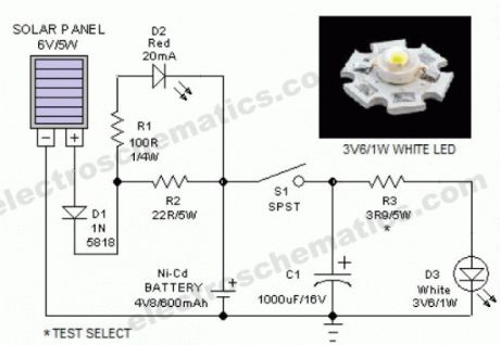

This portable solar lantern circuit uses 6 volt/5 watt solar panels are now widely available. With the help of such a photo-voltaic panel we can construct an economical, simple but efficient and truly portable solar lantern unit. Next important component required is a high power (1watt) white LED module. When solar panel is well exposed to sunlight, about 9 volt dc available from the panel can be used to recharge a 4.8 volt /600 mAh rated Ni-Cd batterypack. Here red LED (D2) functions as a charging process indicator with the help of resistor R1. Resistor R2 regulates the charging current flow to near 150mA.Assuming a 4-5 hour sunlit day, the solar panel (150mA current set by the charge controller resistor R2) will pump about 600 – 750 mAh into the battery pack. When power switch S1 is turned on, dc supply from the Ni-Cd battery pack is extended to the white LED (D3). Resistor R3 determines the LED current. Capacitor C1 works as a buffer.
Note: After construction, slightly change the values of R1,R2 and R3 up/down by trial&error method, if necessary.
Solar Lantern Circuit Schematic
(View)
View full Circuit Diagram | Comments | Reading(1666)
The Schmitt trigger circuit with hysteresis comparator
Published:2012/9/24 22:17:00 Author:Ecco | Keyword: Schmitt trigger , hysteresis comparator
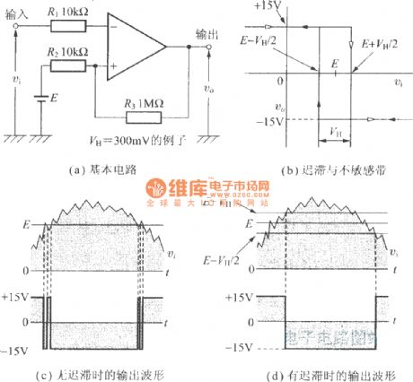
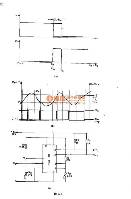
Figure a shows the basic circuit.
Figure b shows hysteresis and insensitive zone.
Figure c shows the output wave withouthysteresis.
Figure d shows the output wave withhysteresis.
(View)
View full Circuit Diagram | Comments | Reading(1659)
Recording head amplifier circuit
Published:2012/9/24 22:14:00 Author:Ecco | Keyword: Recording head amplifier
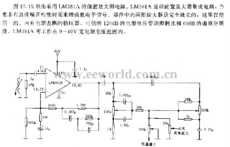
The preamplifier circuit using LM381A is shown in Figure 17.15. LM381A is a dual preamplifier IC which is used to enhance the low-level signal when it is required optimum noise performance. Two sets of amplifier devices are completely independent, the circuit here only uses one group. It contains the power supply decoupling regulator to provide 120dB power supply voltage variation rejection ratio and 60dB channel separation. LM381A can work in wide power supply voltage with range in 9 ~ 40V.
(View)
View full Circuit Diagram | Comments | Reading(1364)
Schmitt trigger circuit with inverting and non-inverting output
Published:2012/9/24 22:08:00 Author:Ecco | Keyword: Schmitt trigger , inverting , non-inverting output
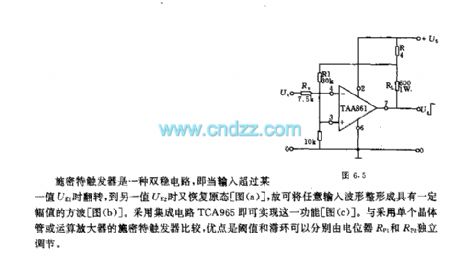
Schmitt trigger is a bistable circuit, when the input exceeds a certain value UE1, it flips and restores the original state until UE2, so it can shape any input waveform to the square wave with a certain amplitude. It uses integrated circuit TCA965 to achieve this function. Compared to using a single transistor or Schmitt trigger with operational amplifier, the advantage is that the threshold and hysteresis can be adjusted independently by potentiometers RP1 and RP2.
(View)
View full Circuit Diagram | Comments | Reading(1731)
The logarithm table circuits using operational amplifier
Published:2012/9/24 20:57:00 Author:Ecco | Keyword: logarithm table, operational amplifier
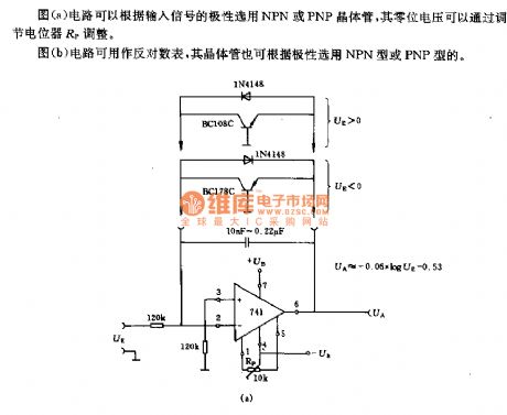
The circuit shown in Fig a can select NPN or PNP transistor in accordance with the polarity of the input signal, and its zero voltage can be adjusted by the potentiometer RP.The circuit shown in Figure b can be used as logarithm table, and its transistor can also select NPN or PNP according to polarity.
(View)
View full Circuit Diagram | Comments | Reading(941)
Wire Break Sensor Alarm circuit
Published:2012/9/25 1:06:00 Author:muriel | Keyword: Wire Break,Sensor,Alarm circuit
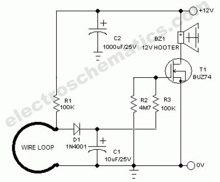
Circuit of a loop sensor based simple security alarm is described here. The sensor loop is nothing but a short length of thin enamelled copper wire, which bridges two input points of the electronic alarm circuit. When the loop is opened the alarm circuit fires an active electric/electronic hooter to raise an ear-splitting audio alert signal. The circuit requires 12 volt dc supply for proper working. When the loop is closed, anode terminal of diode D1 is at ground level and transistor T1 is off. When the loop opens, capacitor C1 is quickly charged via resistor R1 and diode D1, whereupon mosfet T1 comes on so that the hooter (BZ1) is switched on. If the loop is closed again, initial condition is maintained by grounding the anode of D1 and this stops the charging of C1. However, C1 is disharged fairly slowly via R2, so that T1 is not switched off immediately! This ensures that the alarm remains active for a little more time and then goes out slowly. This timeout can be changed by varying the value of R1,R2 and C1. Mosfet T1 may be one of many types of popular n-channel power mosfet, but it should be able to handle the selected 12V hooter of your choice.
Wire break alarm circuit schematic
(View)
View full Circuit Diagram | Comments | Reading(3314)
Electronic Cricket Match Game
Published:2012/9/25 1:05:00 Author:muriel | Keyword: Electronic Cricket,Match Game
This electronic cricket is a present for Kids. This simple battery powered circuit can be used to play Cricket Match with your friends. Each LED in the circuit indicates various status of the cricket match like Sixer, Run out, Catch etc.
The Circuit uses two ICs ,one in the Astable mode and the second in the display driver mode. IC1 is wired as an Astable Multivibrator with the timing elements R1, R2 and C1. With the shown values of these components very fast output pulses are generated from the Astable. Output from IC1 passes into the input of IC2 which is the popular Johnson Decade counter CD4017. It has 10 outputs. Of these 8 outputs are used. Output 9 ( pin9) is tied to the reset pin 15 to repeat the cycle. When the input pin 14 of IC2 gets low to high pluses, its output turns high one by one. Resistor R3 keeps the input of IC2 low in stand by state to avoid false indications.
Electronic Cricket Circuit Diagram
When the Push Switch S1 is pressed momentarily, the Astable operates and all the LEDs run very fast sequentially. When S1 is released, any one of the LED stands lit which indicates the status of the match. For example, if LED D7 remains lit, it indicates Sixer and if LED 8 remains lit, it indicates Catch out.
Label each LED for its status as shown in the diagram. Pressing of S1 simulates Bowling and Running LEDs indicates running of Batsman. (View)
View full Circuit Diagram | Comments | Reading(989)
Power switch with infrared proximity sensor
Published:2012/9/25 1:04:00 Author:muriel | Keyword: Power switch,infrared,proximity sensor
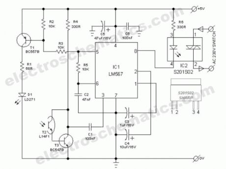

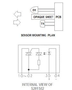
The power switch with infrared proximity sensor is intended for the recognition of obstructions at distances of a few millimetres to a few centimetres. This compact sensor switch can be used to open a water tap via a solenoid valve. In our circuit, the proximity sensor assembly is built from a discrete infrared light emiting diode (LD271-from Siemens/Osram) and a phototransitor (L14F1). A solid-state relay (S201S02-from Sharp) at the output of the circuit enables larger ac mains operated loads (for instance, the solenoid valve) to be switched.
How the infrared switch is working
At the heart the circuit is one renowned phase locked loop tone decoder chip (LM567 from NSC). When the pulsed infrared light signal from D1 is reflected by a nearby object, phototransistor T2 -through T3- provides a signal to pin 3 of IC1. If the signal frequency lies within the same band as that of the internal generator, output terminal (pin8) of IC1 is connected to earth, where upon LED in the solid-state relay (IC2) lights and the relay is energised.
Infrared Power Switch Circuit Diagram
Infrared proximity sensor compornents and parts
(View)
View full Circuit Diagram | Comments | Reading(1912)
| Pages:319/2234 At 20301302303304305306307308309310311312313314315316317318319320Under 20 |
Circuit Categories
power supply circuit
Amplifier Circuit
Basic Circuit
LED and Light Circuit
Sensor Circuit
Signal Processing
Electrical Equipment Circuit
Control Circuit
Remote Control Circuit
A/D-D/A Converter Circuit
Audio Circuit
Measuring and Test Circuit
Communication Circuit
Computer-Related Circuit
555 Circuit
Automotive Circuit
Repairing Circuit