
LED and Light Circuit
Index 44
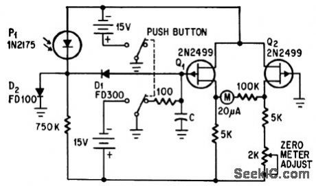
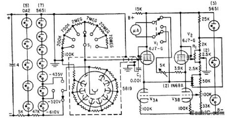
ILLUMINATION_TELEMETER
Published:2009/7/20 12:26:00 Author:Jessie
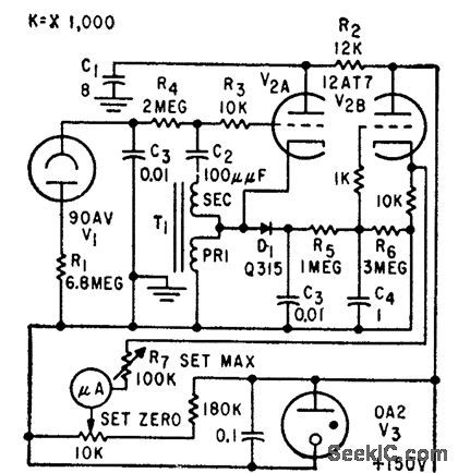
Prf rate of blocking oscillator, controlled by photocell output, can be transmitted over telephone lines to give accurate remote indication of day-light or other light intensity. D1, V2B, and meter provide local indication. Maximum illumination gives highest prf.-E. F. Hasler and G. Spurr, Ways to Measure Light Intensity at a Distance, Electronics, 32:29, p 48-49. (View)
View full Circuit Diagram | Comments | Reading(595)
SQUARE_WAVE_GENERATOR
Published:2009/7/20 12:08:00 Author:Jessie
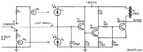
Intensity of light sets pulse and interpulse periods in range from 0.2 to 300 sec, using Schmitt trigger Q1-Q2. Capacitor C is charged and discharged through diodes D1 and D2 consisting of collector-base junctions of 2N1393 phototransistors.-A. K. Horvath, Photodiodes Control Pulse Intervals, Electronics, 38:11, p 72. (View)
View full Circuit Diagram | Comments | Reading(1)
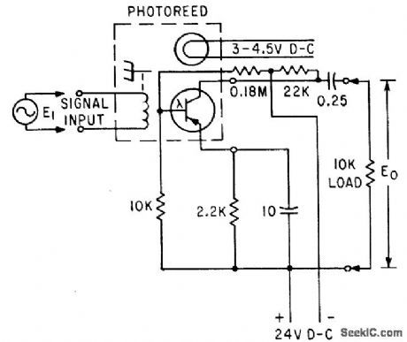
PHOTOREED
Published:2009/7/20 12:07:00 Author:Jessie
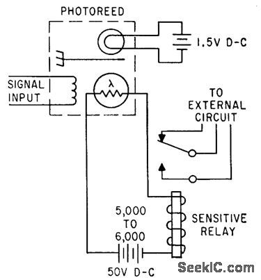
Combines resonant reed relay with photosensor to give frequency-sensitive control in which switching of contacts is accomplished by electro-optical techniques. Photosensor is exposed to intermittent light when reed vibrates like shutter between lamp and sensor.-Frequency-Sensitive Control Uses Light, Electronics, 34:36, p 88-91. (View)
View full Circuit Diagram | Comments | Reading(859)
EYE_MOTION_MVBR_CHAIN
Published:2009/7/20 12:06:00 Author:Jessie
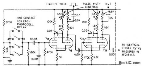
Illuminated photocell triggers mvbr chain. Starter-mvbr is triggered by positive pulse on grid of V1A, but remaining mvbr stages are triggered by negative pulse on cathode. Output pulses are taken from across 6,800-ohm resistor and a-c coupled to gate.-E. L. Thomas, R. Howat, and N. H. Mackworth, Tv Tracker Records Eye Focus Points, Electronics, 33:17, p 57-59. (View)
View full Circuit Diagram | Comments | Reading(628)
PROJECTILE_GLOW_DETECTOR
Published:2009/7/20 12:05:00 Author:Jessie

2N469A phototransistor detects brief low-intensity self-luminous shroud of projectile, and feeds high-gain pulse amplifier that elevates voltage enough to ionize thyratron that initiates discharge of spark-source capacitor for shadowgraph photography.-O. H. Bock and P. L. Clemens, Aerodynamic Measurements in a Hypervelocity Gun Range, Electronics, 34:44, p 33-37. (View)
View full Circuit Diagram | Comments | Reading(740)
MEASURING_FLASHES
Published:2009/7/20 11:46:00 Author:Jessie
Measures and holds intensity of single flash or total value of series of flashes.-C. R. Kerns, FET Circuit Stores Light Measurement, Electronics, 38:22, p 66. (View)
View full Circuit Diagram | Comments | Reading(734)
SINGLE_COLD_CATHODE_AMPLIFIER
Published:2009/7/20 11:45:00 Author:Jessie
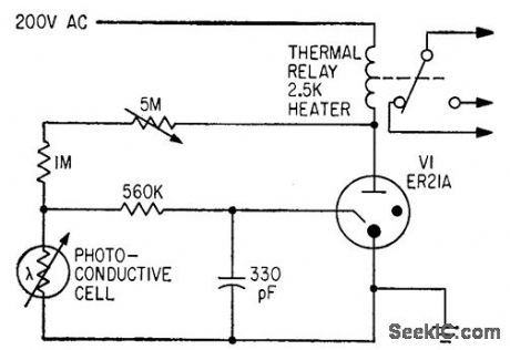
Actuates thermal relay directly from photoconductive cell, for turning on lights at sunset.-P. Bergweger, Photoelectric Control Using Cold Cathode Amplifiers, Electronics, 33:27, p 46-47. (View)
View full Circuit Diagram | Comments | Reading(1079)
CONVEYOR_LINE_JAM_DETECTOR
Published:2009/7/20 11:44:00 Author:Jessie
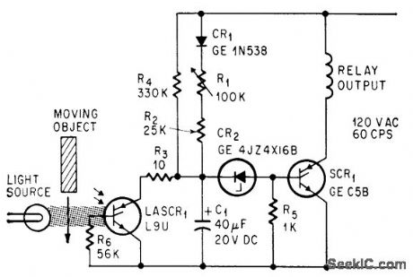
Interruption of light beam to light-activated scr for more than few millisec fires SCR1, opening relay. Momentary interruptions by objects moving normally on conveyor have no effect. Circuit resets automatically when light is restored.-E. K. Howell, Light-Activated Switch Expands Uses of Silicon-Controlled Rectifiers, Electronics, 37:15, p 53-61. (View)
View full Circuit Diagram | Comments | Reading(1460)
SEQUENTIAL_LED_FLASHER_WITH_REVERSIBLE_DIRECTION
Published:2009/7/9 2:13:00 Author:May
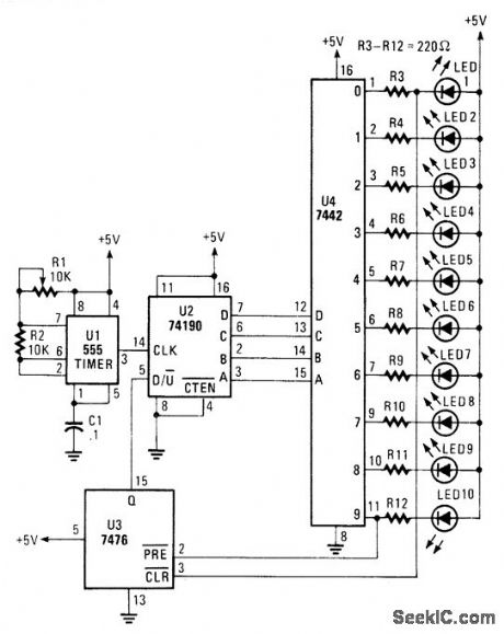
A 555 timer clocks a 74190 up/down counter. The 74190 drives BCD decoder driver 7442. The 7476 is used to reverse the count on 0 and 9, which results in an up-down-up-down count sequence. (View)
View full Circuit Diagram | Comments | Reading(6095)
CELL_GROWTH_MICROPHOTOMETER
Published:2009/7/20 11:35:00 Author:Jessie
Permits direct measurement of transmittance while stained cells are studied visually at magnification of 1,000 X. Beam-splitting mirror sends 90% of light to multiplier phototube. Maximum current sensitivity is 0.01 microamp full scale.-E. Gordy, Microphotometer Aids Biologists, Electronics, 32:28, p 62-64. (View)
View full Circuit Diagram | Comments | Reading(580)
MEASURING_TRANSIENT_LIGHT
Published:2009/7/20 11:27:00 Author:Jessie
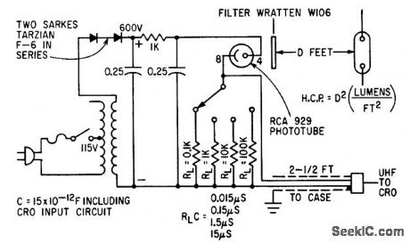
Used with cro for measuring rapidly changing light output of flashlamps.-H. E. Edgerton and R. O. Shaffner, Measuring Transient Light With Vacuum Phototubes, Electronics, 34:34, p 56-57. (View)
View full Circuit Diagram | Comments | Reading(717)
PHOTOSWITCHING_CIRCUIT
Published:2009/7/20 11:23:00 Author:Jessie
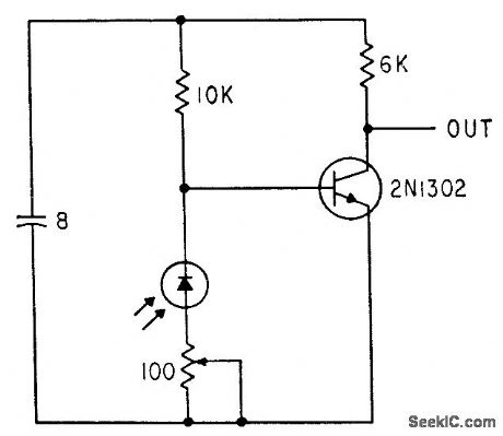
Circuit provides amplification along with switching for photo-diode mounted to pick up changes in light reflected by encoders disk.-F. W. Kear, How to Select Shaft-Position Encoders, Electronics, 35:35, p 48-51. (View)
View full Circuit Diagram | Comments | Reading(1137)
PHOTODIODE_PICKOFF
Published:2009/7/20 11:22:00 Author:Jessie
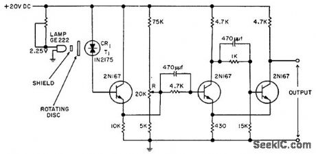
Used in measuring servo system lag. Responds to slot milled near edge of rotating disk. Accuracy is 0.17°in either direction. -J. D. Habegger, Photo Diode Pickoff Gives Accurate Angular Reference, EEE, 10:16, p 37. (View)
View full Circuit Diagram | Comments | Reading(770)
PHOTOELECTRIC_BANDPASS_FILTER
Published:2009/7/20 11:21:00 Author:Jessie
Output of phototransistor varies linearly with input signal at resonant frequency of photoreed, to give function of bandpass filter.-Frequency-Sensitive Control Uses Light, Electronics, 34:36, p 88-91. (View)
View full Circuit Diagram | Comments | Reading(778)
PHOTOCELLS_MONITOR_DEWPOINT_ON_METALLIC_MIRROR
Published:2009/7/20 11:08:00 Author:Jessie

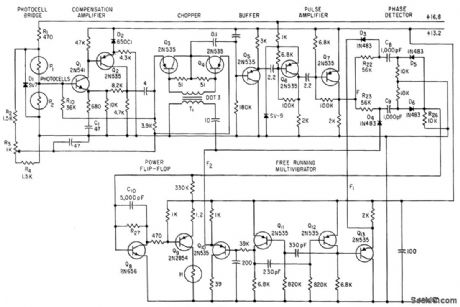
Two photocells in bridge circuit develop error signal for bang-bang servo that uses power flip-flop to turn heater H of metallic mirror on and off, to maintain constant-thickness film of dew or frost on mirror. Two-transistor chopper and a-c amplifier eliminate drift problems.-H. It. Farrah and P. E. Sherr, New Approach to Weather Data: Every Plane a Station, Electronics, 36:28, p 38-41. (View)
View full Circuit Diagram | Comments | Reading(752)
TAPE_READER
Published:2009/7/20 11:01:00 Author:Jessie
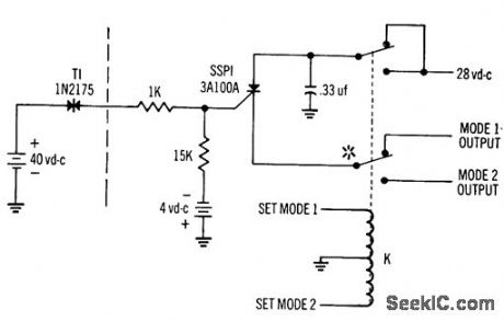
Simplified circuitry, few components, storage capability, and output power above 20 W are advantages of using silicon controlled switch in place of multistage amplifier for photoelectric paper-tape readers. Thyratron-like characteristics maintain output after photoelectric stimulus disappears, until cut off by control circuit. Asterisk on one pole of relay K indicates that similar pole is required for each bit in two-mode operation.-SCR Switch Eliminates Amplifier for Photoelectric Readers, Electronic Circuit Design Handbook, Mactier Pub. Corp., N.Y., 1965, p 222. (View)
View full Circuit Diagram | Comments | Reading(885)
LED_FLASHER
Published:2009/7/9 2:03:00 Author:May
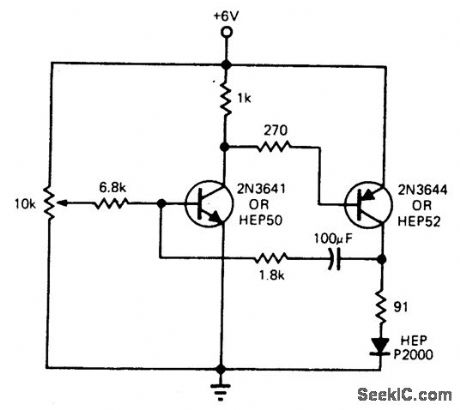
This circuit is designed to flash an LED. The 100-μF capacitor can be changed to alter the flash rate as desired. (View)
View full Circuit Diagram | Comments | Reading(0)
AUTOMATIC_LIGHT_CONTROL
Published:2009/7/20 11:00:00 Author:Jessie
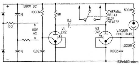
High-sensitivity vacuum phototube responds to illumination by changing mark-space periods of coldcathode mvbr so V2 is on most of the time when illumination is excessive. Thermal relay then gets heated sufficiently to switch off lights.-P. Bergweger, Photoelectric Control Using Cold Cathode Amplifiers, Electronics, 33:27, p 46-47. (View)
View full Circuit Diagram | Comments | Reading(830)
PAPER_FLAW_DETECTOR
Published:2009/7/20 10:49:00 Author:Jessie
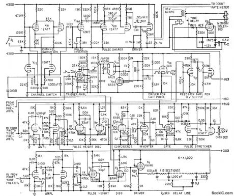
Locates defects in paper despite photomultiplier noise amplitudes comparable to flaw-signal amplitudes. Two identical phototubes are used, each with identical preamplifiers, amplifiers, and pulse height discriminators. One phototube looks at paper ahead of other. Output of leading phototube is delayed to give same effect as if both looked at same area at same time. Pulses due to real defects then occur at same time and pass coincidence circuit. Pulses due to noise are random in time and do not pass.-M. P. MacMartin, Sensitive Flaw Detector Solves Noise Problems, Electronics, 33:16, p 64-66. (View)
View full Circuit Diagram | Comments | Reading(947)
PHOTOELECTRIC_GAGING
Published:2009/7/20 10:36:00 Author:Jessie
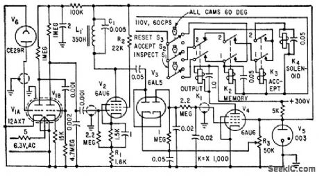
Checks dimensions of machine parts while they are rotating. Fail-safe circuit assures that only satisfactory pieces are accepted. Sorter is initially calibrated to desired sensitivity with go and no-go gages.-J. C. Frommer, Fail-Safe Photoelectric Inspection for Industry, Electronics, 32:31, p 74-75. (View)
View full Circuit Diagram | Comments | Reading(748)
| Pages:44/72 At 204142434445464748495051525354555657585960Under 20 |
Circuit Categories
power supply circuit
Amplifier Circuit
Basic Circuit
LED and Light Circuit
Sensor Circuit
Signal Processing
Electrical Equipment Circuit
Control Circuit
Remote Control Circuit
A/D-D/A Converter Circuit
Audio Circuit
Measuring and Test Circuit
Communication Circuit
Computer-Related Circuit
555 Circuit
Automotive Circuit
Repairing Circuit