
LED and Light Circuit
Index 59
MOS_LAMP_DRIVER
Published:2009/6/17 2:10:00 Author:May
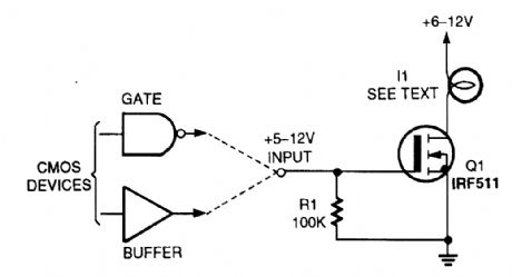
The circuit shows a way of using a MOSFET as a load driver. I1 can be a lamp, or any other load, that does not exceed the current rating of Q1. (View)
View full Circuit Diagram | Comments | Reading(849)
RUNNING_LIGHT_SEQUENCE_
Published:2009/6/17 2:10:00 Author:May

This running light sequencer drives 16 LEDs and runs from a 12-V supply. C1 can be varied to alter the rate of operation. (View)
View full Circuit Diagram | Comments | Reading(4914)
120_ac_SHIMMERING_LIGHT
Published:2009/6/17 2:06:00 Author:May
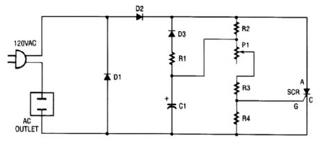
You can turn any ordinary household bulb into one that shimmers or blinks. This circuit works on any incandescent light up to 200 W, and runs on standard 120 Vac. The circuit uses an SCR to cause an ordinary lamp to shimmer. Note that one side of the lamp is connected directly to 120 Vac, and the other side of the lamp goes to the cathode of the SCR. As ac voltage is brought into the circuit through the line cord, it is full-wave rectified by diodes Dl and D2. That changes the ac to dc, and a portion of that dc voltage is applied to capacitor C1 through R2. Diode D3 blocks the (+) dc voltage so that only the voltage from the path of RI and D3 is clear. That forms an oscillator, which has a frequency de-termined by the setting of potentiometer PI (because the other components have fixed values).Remember to use extreme caution when using a device that connects to the ac line. Never use it outside or near water and always mount the entire kit inside a wooden or plastic (insulated) box to prevent any contact with the ac voltage. (View)
View full Circuit Diagram | Comments | Reading(948)
LIGHT_SEQUENCER
Published:2009/6/17 1:52:00 Author:May


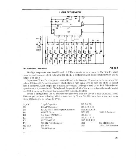
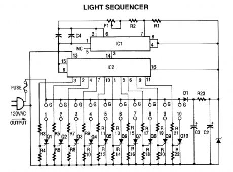
The light sequencer uses two ICs and 10 SCRs to create an ac sequencer. The first IC, a 555 timer, is used to provide clock pulses for IC2. The IC is configured as an astable multivibrator, and its output is on pin 3.Capacitors C1 and C4, along with resistor R2 and potentiometer PI, control the frequency of the pulses. IC2 is a 4017 Johnson counter, which shifts a high-signal level to each one of its 10 output pins in sequence. Each output pin is resistively coupled to the gate lead on an SCR. When the re-spective output pin on the 4017 is high and the positive half of the ac cycle is on
the anode lead of the SCR, it turns on. The lamp that is connected to its anode lights.Power is brought into the PC board by the line cord, then the circuit is fuse-protected. Diode LD1 changes the ac to pulsating, which is smoothed by CZ and C3. R23 limits the current, and zener diode D2 limits the dc voltage to 6 Vdc.
CI,040.1-μF Capacitor R2,R4,R6,C2 100-μF Capacitor R8,R10,R12,C3 47-μF, 350-V Electrolytic Capacitor R14,R16,R18D1 1N4007 Diode R20,R22 100-kΩ ResistorD2 6-V Zener (M747814)R3,R5,R7IC1 555 Timer IC R9,R11,R13IC24017 CMOS IC R15,R17,R19P1 500-kΩ Potentiometer R21 2.2-kΩ ResitstorQ1-Q10 106 SCR R23 15-kΩ 7-W ResistoR1 560-Ω Resistor (View)
View full Circuit Diagram | Comments | Reading(3198)
LED_Christmas_Tree_Light_Flasher
Published:2009/6/17 0:40:00 Author:May
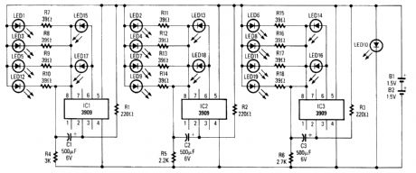
Three individual flashing circuits that use an LM3909 LED flasher/oscillator IC create the appearance of a pseudo-random firing order. The combination of C1/R4, C2/R5, and C3/R6 control the blink rate, which is between 0.3 and 0.8s, and the inherent wide tolerance range (-20% to +80%) of standard electrolytic capacitors add to the irregularities of the blink cycles. The continuous current drain is about 10 mA; however, if you decrease the values of R4 through R6 or C1 through C3 in order to increase the blink rate, the current will then increase proportionally.
Note in particular that extemal current-limiting resistors aren't needed for LED13 through LED18; the resistors are built into the ICs. LED10, which serves as the tree's star, is a special kind of flashing LED that blinks continuously at a fixed rate. (View)
View full Circuit Diagram | Comments | Reading(2993)
LED_Flasher_for_2_to_10_LEDs
Published:2009/6/17 0:10:00 Author:May
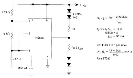
This LED flasher has double-ended output connection. The circuit can be used with 1 to 5 LEDs on each side as indicated. (View)
View full Circuit Diagram | Comments | Reading(743)
Super_LED_Flasher
Published:2009/6/17 0:07:00 Author:May
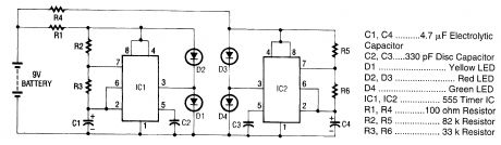
The super LED flasher is actually two complete LED flasher circuits on one circuit on one circuit board. The first LED flasher is made up of IC1 and LEDs D1 and D2. IC1 is a 555 timer IC configured as an astable (free-running) multivibrator with its output on pin 3.
The frequency of the 555's oscillation is controlled by R2, R3, and C1. Resistor R1 limits the input voltage to a low enough level to prevent damage to the IC. As the 555 IC oscillates, the output of pin 3 goes high (+) then low (-). When the output is high it supplies current to D1, which lights up.When it is low, pin 3 sinks current and D2 lights up. This happens because LEDs are polarity-sensi-tive (like all other diodes, they permit current flow in only one direction) and one lead of each LED has been connected to the respective polarity needed to light that LED.
The second LED flasher, made up of IC2 and LEDs D3 and D4, operates in the same way as the first LED flasher. (View)
View full Circuit Diagram | Comments | Reading(1726)
Dark-Activated_LED_Flasher
Published:2009/6/16 23:58:00 Author:May
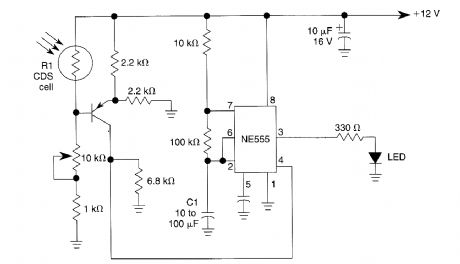
This circuit can be used as a small beacon or marker light, amd toys or novelty items. R1 is an LDR that has≥10 kΩ dark-resistance, or a CDS photocell. C1 determines the flash rate. (View)
View full Circuit Diagram | Comments | Reading(1097)
LED_Flashers
Published:2009/6/16 23:54:00 Author:May
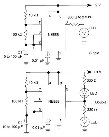
A 555 is used to switch an LED on and off. C1 determines the flash rate. Single ended (one LED) and double-ended (altemating) flashers are shown. (View)
View full Circuit Diagram | Comments | Reading(826)
MODULATED_LIGHT_RECEIVER
Published:2009/6/16 23:48:00 Author:May
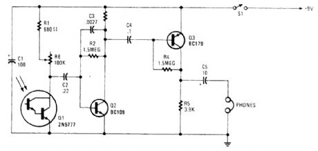
Using a phototransistor, this receiver will detect and demodulate a modulated light beam. R6 af-fects sensitivity. (View)
View full Circuit Diagram | Comments | Reading(2276)
36_LED_Flasher_Driver
Published:2009/6/16 23:48:00 Author:May
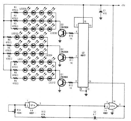
Originally intended as a 3-bell animation circuit for Christmas decorations, the circuit can be used for many other purposes that require a flasher of this kind. By re-connerting U2(see the data manual), more than three outputs can be be obtained. (View)
View full Circuit Diagram | Comments | Reading(1922)
FANTASTIC_SIMULATED_LASER
Published:2009/6/16 23:37:00 Author:May
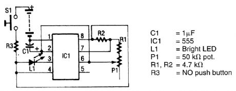
The circuit uses a 555 timer IC to power an ultrabright LED. The output is a pulsing red light that can be projected using lenses. An ultrabright Stanley LED, capable of 300-millicandle output, is tied to pin 3 of the 555 timer IC. That IC has been configured as an astable multivibrator. The fre-quency of this multivibrator is controlled by R1, R2, C1, and P1. You can vary the frequency by ad-justing P1, which changes the output from a slow blinking to a fast pulsating light. Resistor R3 is used to limit the current flowing into the circuit to a safe value, to prevent the LED and the IC from bum-ing out. Switch S1 applies power to the circuit when its button is pressed. (View)
View full Circuit Diagram | Comments | Reading(954)
Sequential_Flasher
Published:2009/6/16 23:36:00 Author:May

A 555 timer, IC1, drives a 4017 CMOS decade counter. Each of the 4017's first four outputs drives a CA3079 zero-voltage switch. Pin 9 of the CA3079 is used to inhibit output from pin 4, thereby disabling the string of pulses that the IC normally delivers. Those pulses occur every 8.3 ms, i.e., at a rate of 120 Hz. Each pulse has a width of 120 μs. Because of the action of the CA3079, the lamps connected to the triacs turn on and off near the zero crossing of the ac waveform. Switching at that point increases lamp life by reducing an inrush of current that would happen if the lamp were turned on near the high point of the ac waveform. In ad-dition, switching at the zero crossing reduces radio frequency interference (RFI) considerably. Cau-tion: The CA3079s are driven directly from the 117-Vac power line, so use care. (View)
View full Circuit Diagram | Comments | Reading(2977)
BI_COLOR_INDICATOR
Published:2009/6/16 22:36:00 Author:May
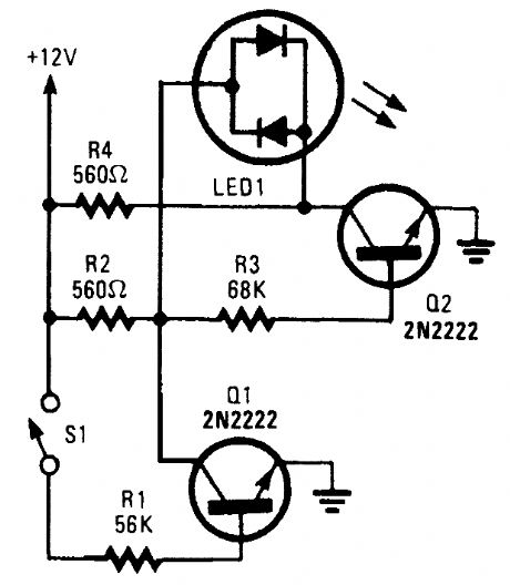
With S1 open, base bias is supplied to Q2 through avoltage divider (formed by R2 and R3), thus turning on the green element in the LED. That indicates that power is being supplied to the project.Ifyou close S1, current through RI biases Q1 on, thereby grounding the voltage divider and turning off Q2. That reverses the flow of current through the LED, which causes its red element to light. That indicates that the circuit is under power and S1 (really a DPDT switch), whose remaining section controls another circuit, is active. In this circuit, a bi-color LED is used to indicate when a circuit is under power and the status of S1. In that way, the LED does the job of two indicators. (View)
View full Circuit Diagram | Comments | Reading(1222)
POLARITY_INDICATOR
Published:2009/6/16 22:33:00 Author:May
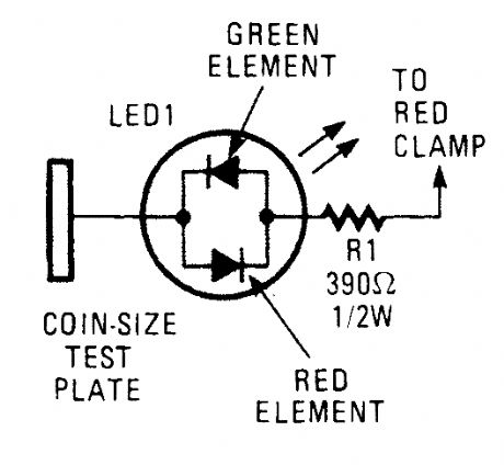
This circuit consists of a tri-color LED, a resistor, wire, and a coin-size test plate. You will have to build two such circuits-one for each black clamp on a set of auto battery jumper cables. The author installed the circuits inside the black clamps themselves using lengths of wire to make the connections to the red clamps.The first step is to connect one red clamp to what you believe is the positive post on the okay battery. Then, touch the test plate on the black clamp at the end of the cable to the negative termi-nal on the good battery. The LED will light red if the red clamp is on the wrong terminal. If so move the clamp to the other poJt and check again. If all is well, the LED will light green. Pick up the other black clamp and connect it to the remaining post on the good battery.Connect the remaining red clamp to what you assume to be the positive terminal on the bad battery. Now, touch the test plate on the remaining clamp to the engine block or a bare area on the dead car's frame. If the LED appears or doesn't glow, switch the red clamp to the other terminal and test again. When the LED glows green, attach the black clamp to the car's frame (which will prevent any sparks from occurring near the battery). When you remove the clamps, take the clamps off in reverse order to avoid sparks. (View)
View full Circuit Diagram | Comments | Reading(1)
BRAKE_AND_TURN_INDICATOR
Published:2009/6/16 2:43:00 Author:May
This might be a quick solution to getting the two-wire truck harness to support both turn and braking indications. (View)
View full Circuit Diagram | Comments | Reading(751)
HEADLIGHTS_ON_REMINDER
Published:2009/6/16 2:43:00 Author:May
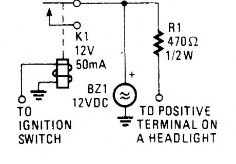
This circuit will sound alarm BZ1 if the ignition is turned off with the headlights on. (View)
View full Circuit Diagram | Comments | Reading(705)
HEADLIGHT_FLASHER
Published:2009/6/16 2:35:00 Author:May
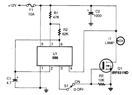
The headlight flasher is nothing more than a 555 oscillator/timer that's configured as an astable multivibrator (oscillator). Its input is used to drive the gate of an IRF53IND hexFET, which, in turn, acts like an on/off switch, turning the lamp on and off at the oscillating frequency (1 Hz). (View)
View full Circuit Diagram | Comments | Reading(2586)
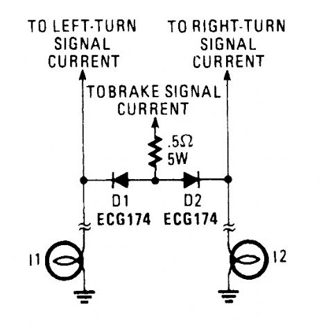
BRAKE_AND_TURN_SIGNAL_LIGHT_CIRCUIT
Published:2009/6/16 1:48:00 Author:May

This circuit enables single-filament tail lights to serve as combination brake lights and turn signals. (View)
View full Circuit Diagram | Comments | Reading(917)
4543B_COMMON_CATHODE_LED_DRIVER
Published:2009/6/15 23:50:00 Author:May
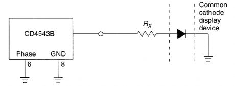
This circuit shows a way of driving a com-or an LED with a common cathode display segment CD4543B. (View)
View full Circuit Diagram | Comments | Reading(755)
| Pages:59/72 At 204142434445464748495051525354555657585960Under 20 |
Circuit Categories
power supply circuit
Amplifier Circuit
Basic Circuit
LED and Light Circuit
Sensor Circuit
Signal Processing
Electrical Equipment Circuit
Control Circuit
Remote Control Circuit
A/D-D/A Converter Circuit
Audio Circuit
Measuring and Test Circuit
Communication Circuit
Computer-Related Circuit
555 Circuit
Automotive Circuit
Repairing Circuit