
LED and Light Circuit
Index 43
ad_dc_INDICATOR
Published:2009/7/9 5:22:00 Author:May
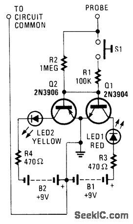
By using two switching transistors and two LEDs, this circuit can distinguish low-level ac and dc sig-nals. If the red LED illuminates, the signal is positive dc. If the yellow LED lights, the signal is negative dc.If the signal is ac, both LEDs will light. (View)
View full Circuit Diagram | Comments | Reading(885)
ELECTRONIC_IGNITION
Published:2009/7/9 5:18:00 Author:May
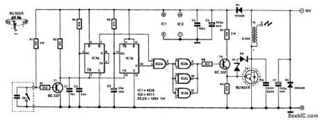
This electronic ignition circuit is intended to be inserted into a car's conventional ignition system. In effect, it replaces the original 12-V switching circuit in the primary winding of the coil by one generating more than 100 V. It thereby converts a current circuit, which is upset by lead and stray resistance, into a voltage circuit that is much more efficient.
The pulses emanating from the contact breaker, shown at the extreme lower left-hand side of the dia-sram, are applied to transistor T1 and subsequently differentiated by R3/C1. This causes a negligible igni-tion delay. The current through the contact-breaker points is determined by the value of R1. This value has been chosen to ensure that the points remain clean.
Transistor T1 is followed by two monostables, IC1A and IC1B, which are both triggered by the output pulses of T1. However, whereas IC1A is triggered by the trailing edge, IC1B is triggered by the leading edge.
Monostable IC1A passes a pulse of about 1.5 ms (determined by R4/C2) to NAND gate IC2A. This gate switches off high-voltage Darlington T3 via gates IC2B, IC2C and IC2D, and driver T2, for the dura-tion of the pulse. Gate IC2 ensures that T3 is switched on only when the engine is running, to prevent a current of some amperes flowing through the ignition coil.
As long as pulses emanate from the contact breaker, ICIB is triggered and its Q output remains logic high. The mono time of this stage is about 1 s and is determined by R5/C3.
Darlington T3 is switched on via T2 and IC2A through IC2D as long as IC1A does not pass an ignition pulse. When the engine is not running, the Q output of IC2B goes low after 1 s and this causes T2 and T3 to be switched off. The two series-connected 180-V zener diodes protect the collector of the BU932R against too high of a voltage. The Darlington must be fitted on a suitable heatsink. (View)
View full Circuit Diagram | Comments | Reading(6555)
VISUAL_CW_OFFSET_INDICATOR
Published:2009/7/9 5:17:00 Author:May
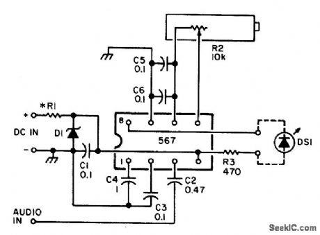
An NE567 tone decoder, tuned to the transceiver's CW offset frequency, ensures that the transceiver will be transmitting on the same frequency as the received CW signal. Simply tune the transceiver so that the LED lights. Eight to 13 Vdc is required; this can be taken from the transceiver supply or an extra battery. Audio is taken from the speaker or headphone output. (View)
View full Circuit Diagram | Comments | Reading(1070)
AUDIO_AMPLIFIER_VOLUME_INDICATOR
Published:2009/7/9 5:12:00 Author:May
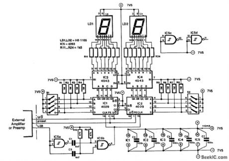
The indicator IS intended for use with an audio gmplifier or preamp⒒fter, but it can also be used in other applcations where a number of steps or changes must be counted rapidly.To prevent interferencewith the audio signal,the circuit is a static design.Thus,if the volume control is not adjusted,the circuit does nothint.
The circuit does not need an external clock signal,because this IS derived from any changes h theleast significant bit (LSB).This is done by two differentiating networks:R9/C1 and RIO/C2,which double the frequencY of an available LSB signal.
Moreover,to ensure that the counters of the indicator remain in step with the volume control,signals“up/down”and preset from the preamplifier are used.It might seem rather extravagant to couple the state of the counters in the prearnplifter with that the present counters,but it is a good way to keep the connections between the two units to a minimum,Furthermore,the present counters operate In 8-bit BCD,instead of 6-bit binary as used by those h the volume control (in the preamplifier).All that is required to display the state of the volume control are a couple of BCD-to-7-segment decoders and 7-segment displays.
The preset h the indicator must be set h BCD code,Leading zeros are not suppressed so numbers up to and including 9 are displayed,startingwith a 0,The DIP switches and resistors RI through R8 In the diagram can be omitted if only one fixed preset is likely to be used.The resistors should be replaced by jump leads. (View)
View full Circuit Diagram | Comments | Reading(3026)
THIRD_BRAKE_LIGHT
Published:2009/7/9 4:56:00 Author:May
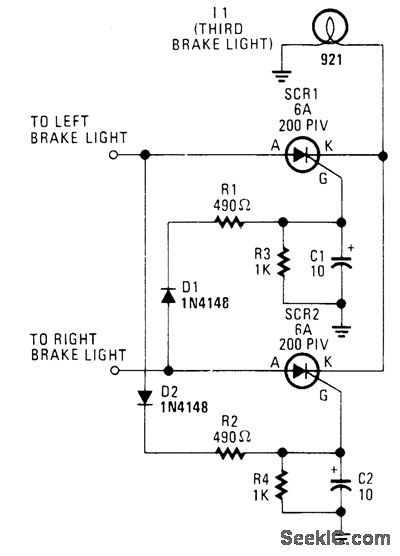
The circuit is designed to light (via SCR1 and SCR2) only when both the left and right brake lights are activated. The circuit operates on 12-V negative-ground systems. When the brake pedal is depressed, 12 V is applied to the left and right brake lights. The gates of the two SCRs are trig-gered and current flows through the SCRs, which turns on the third brake light. (View)
View full Circuit Diagram | Comments | Reading(1016)
INTERIOR_CONVENIENCE_LIGHT
Published:2009/7/9 4:53:00 Author:May

When the door is closed, this circuit keeps the dome light on for a period determined by R1/C1. The time is approximately (1.1)R1 x C1. (View)
View full Circuit Diagram | Comments | Reading(878)
CAR_LIGHTS_MONITOR
Published:2009/7/9 4:48:00 Author:May

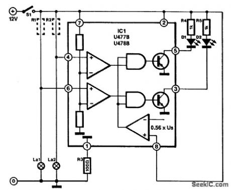
This circuit is for the purpose of monitoring automotive lighting. Two special ICs are available from Telefunken that are designed to measure the current through a light bulb. In practice, detecting whether a current flows through a bulb or not is a most suitable way of determining whether the bulb still works.
If a small resistance is connected in series with a bulb, a small voltage drop will develop across it when the bulb lights (R1 and R2 in the diagram). Each IC can cope with only two bulbs, so three or four ICs are needed per car. The junction of the bulb and resistor is connected to one of the inputs (pin 4 or pin 6) of the IC. The potential across the resistor is compared in the IC with an internal reference voltage. Depend-ing on which of the tWo ICs is used, the voltage drop must be about 16 mV (U477B) or 100 mV (U478B). This voltage drop is so small that it will not affect the brightness of the relevant bulb.
The value of the series resistor is determined quite easily. If, for instance, it is in series with the brake light (normally 21 W), the current through the bulb, assuming that the vehicle has a 12-V battery, is 21÷12=1.75 A. The resistance must then be of 16÷1.75=9 mΩ (U477B) or 100÷1.75=57 mΩ (U478B).
These resistors can be made from a length of resistance wire (available from most electrical retailers).Failing that, standard circuit wire of 0.7 mm diameter can be used. This has a specific resistance of about 100 mΩ per meter. However, in most cars, the existing wiring will have sufficient resistance to serve as series resistor.
LEDs can be connected to the outputs of the IC (pins 3 and 5). These will only light if the relevant car light fails to work properly. (View)
View full Circuit Diagram | Comments | Reading(1484)
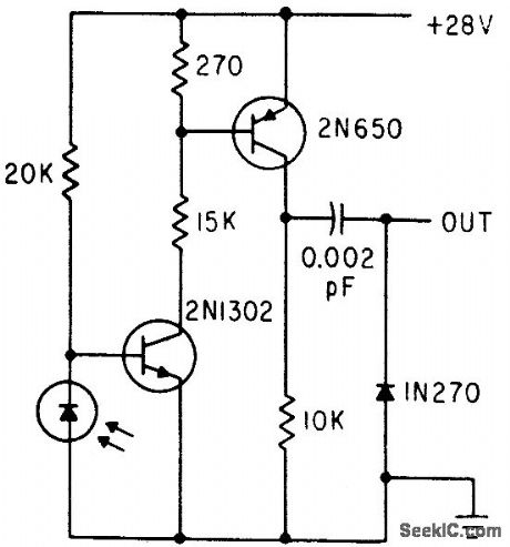
LAMP_CONTROL
Published:2009/7/20 7:17:00 Author:Jessie
Phototransistor Q1 senses lamp intensity and controls firing angle of scr's Q3 and Q4 through unijunction transistor Q2.-R. L. Carvajal, Phototransistor Regulates Illumination Intensity, Electronics, 38:20, p 101. (View)
View full Circuit Diagram | Comments | Reading(978)
PHOTOMULTIPLIER_FOR_GAMMA_RAY_SPECTROMETER
Published:2009/7/20 7:13:00 Author:Jessie
Flashes of light from scintillator crystal are picked up by EM19579 photomultiplier to measure underwater gamma radiation, and amplified output of photomultiplier is fed to surface equipment through coaxial cable that also serves as 2,000-V high-voltage lead for anode.-G. K. Riel, New Underwater Gamma Spectrometer, Electronics, 36:10, p 56-8. (View)
View full Circuit Diagram | Comments | Reading(1204)
LAMP_TRIGGERED_SCR_GIVES_VARIABLE_PHASE_CONTROL_OF_POWER
Published:2009/7/20 7:34:00 Author:Jessie
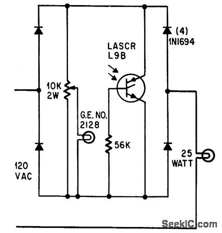
Miniature 2128 lamp with low-mass filament triggers light-activated scr in 1 millisec when lamp is across scr and in about 3 cycles at low a-c lamp voltage. Potentiometer thus provides phase control of scr for dimming 25-w lamp or equivalent-wattage load.-E. K. Howell, Light-Activated Switch Expands Uses of Silicon-Controlled Rectifiers, Electronics, 37:15, p 53-61. (View)
View full Circuit Diagram | Comments | Reading(1261)
AGC_FOR_PHOTODETECTOR_AMPLIFIER
Published:2009/7/20 7:33:00 Author:Jessie
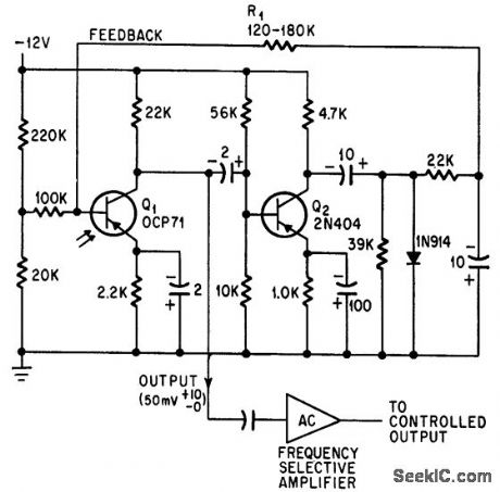
Holds photodetector output signal constant within 2 db for 4-db variation in ambient light level. -P. H. Sydenham, Photodetector Gain Control Aids Signal Discrimination, Electronics, 38:23, p 111. (View)
View full Circuit Diagram | Comments | Reading(805)
FLICKER_LIGHT
Published:2009/7/9 2:20:00 Author:May
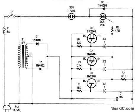
This circuit will produce a flicker light effect with an ordinary incandescent lamp. Three UJT relaxation oscillators fire the SCR in a pattern. (View)
View full Circuit Diagram | Comments | Reading(1563)
TIME_OUT_TIMER
Published:2009/7/20 19:55:00 Author:Jessie
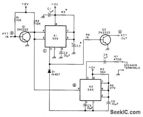
Prevents unnecessary repeater timeouts by generating warning tone in loudspeaker of mobile transceiver when transmitter is on too long. Normal push-to-talk line is broken and connected to points A and D. Pushing talk button starts timer. Time in seconds is 1.1 R3C3, with R3 in megohms and 03 in microfarads. Thus, 1 megohm and 27μF give 30 s, while 2 megohms and 81μF give 180 s.-J. A. Kvochick, Keeping the Wind Down, 73 Magazine, Feb. 1977, p 50. (View)
View full Circuit Diagram | Comments | Reading(1009)
ACCESS_TONE_GENERATOR
Published:2009/7/20 19:54:00 Author:Jessie
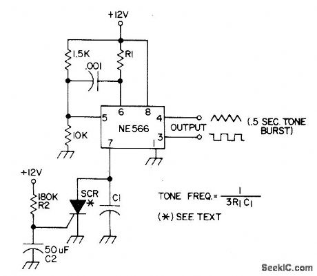
Produces audio burst for 0.5 s at frequency determined by R1 and C1, for use with FM transceiver as subaudible tone generator to access repeaters. Provides buffered outputs of square waves as well as triangle waves. Uses NE566 function generator as voltage-controlled oscillator having excellent stability and linearity, R1 should be between 2K and 20K. SCR should be type that triggers at 70μA.-E. Kanter, PLL IC Applications for Hams, 73 Magazine, Sept. 1973, p 47-49. (View)
View full Circuit Diagram | Comments | Reading(2222)
ACCESS_TONE_BURST
Published:2009/7/20 19:53:00 Author:Jessie
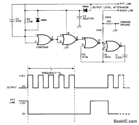
Generates 1-s tone burst at specified audio frequency such as 1800 Hz each time transmitter is energized, to pro-vide access to a desired repeater. Uses CMOS CD4001AE quad NOR gate, which is small enough so entire circuit can be fitted in micro-phone housing. Gates are connected as astable MVBR, with ON time of tone burst determined by R2C2 time constant, triggered by push-to talk switch (PTT). Large capacitor C3 powers MVBR during burst, with capacitor normally charged to 12 V through PTT circuit during receive. Supply voltage is taken through Prr relay in transmitter.-G. Hinkle, Tone-Burst Genera-tor for Repeater Accessing, Ham Radio, Sept, 1977, p 68-69. (View)
View full Circuit Diagram | Comments | Reading(1242)
OPTICAL_PUSH_PULL_COUPLING
Published:2009/7/20 12:35:00 Author:Jessie
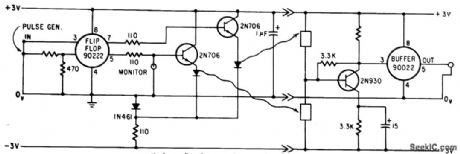
Two gallium arsenide light sources and two high-speed silicon photoconductors provide push-pull optical coupling between integrated-circuit flip-flop ond buffer, with two transistors in push-pull amplifier overcoming losses of optical coupling.-T. E. Bray, Switching With Light, Electronics, 38:22, p 58-65. (View)
View full Circuit Diagram | Comments | Reading(773)
LIGHT_ACTIVATED_SCR_TIME_DELAY
Published:2009/7/20 12:32:00 Author:Jessie
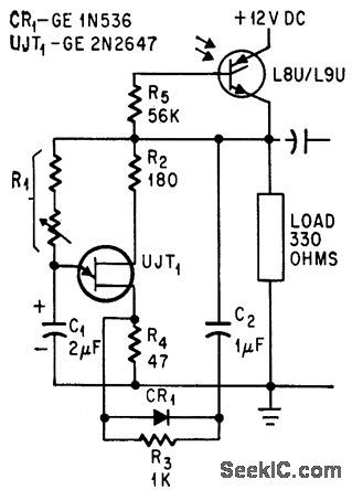
Boot-strapped unijunction transistor interrupts load current at desired delay interval (determined by R1 and C1) after short pulse of light hits glass-window scr L8U.-E. K. Howell, Light-Activated Switch Expands Uses of Silicon-Controlled Rectifiers, Electronics, 37:15, p 53-61. (View)
View full Circuit Diagram | Comments | Reading(896)
FLASH_ACTUATED_SCR_DELAY
Published:2009/7/20 12:29:00 Author:Jessie

Fractional-cycle light pulse fires glass-window scr at any phase angle, while values of circuit components determine number of cycles of conduction before turn off at zero current.-E. K. Howell, Light-Activated Switch Expands Uses of Silicon-Controlled Rectifiers, Electronics, 37:15, p 53-61. (View)
View full Circuit Diagram | Comments | Reading(1000)
PHOTOREED_OSCILLATOR
Published:2009/7/20 12:28:00 Author:Jessie
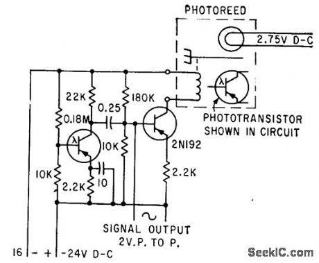
Gives good sinewave output at reed frequency, using phototransistor to sense chopped light and transistor to boost output voltage. Can be used for remote control, telemetry, and logic functions.-Frequency-Sensitive Control Uses Light, Electronics, 34:36, p 88-91. (View)
View full Circuit Diagram | Comments | Reading(664)
PHOTODIODE_AMPLIFIER
Published:2009/7/20 12:27:00 Author:Jessie
Used with transmitted-light encoder disk to produce pulses with correct amplitude and rise time to drive logic circuit.-F. W. Kear, How to Select Shaft-Position Encoders, Electronics, 35:35, p 48-51. (View)
View full Circuit Diagram | Comments | Reading(0)
| Pages:43/72 At 204142434445464748495051525354555657585960Under 20 |
Circuit Categories
power supply circuit
Amplifier Circuit
Basic Circuit
LED and Light Circuit
Sensor Circuit
Signal Processing
Electrical Equipment Circuit
Control Circuit
Remote Control Circuit
A/D-D/A Converter Circuit
Audio Circuit
Measuring and Test Circuit
Communication Circuit
Computer-Related Circuit
555 Circuit
Automotive Circuit
Repairing Circuit