
LED and Light Circuit
Index 49
LED_DISPLAY_FOR_TTL
Published:2009/7/2 22:22:00 Author:May
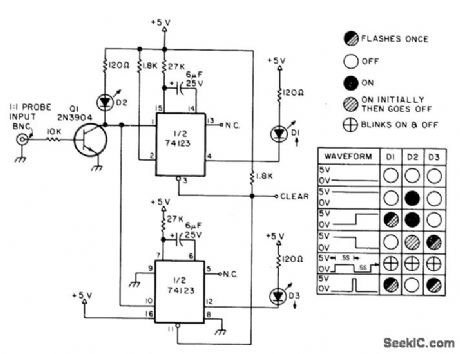
Useful for observing TTL levels when CRO is not available. A1 and A2 are 74123 dual retriggerable mono MVBRs with clear, used to tum on LEDs when input transitions are detected. Even very short pulses are made visible because mono stretches pulse length. Table shows how LED indications are interpreted.-B. Voight, The TTL One Shot, 73 Magazine, Feb,1977, p 56-58. (View)
View full Circuit Diagram | Comments | Reading(2789)
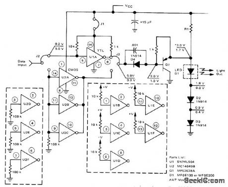
RED_GREEN_LEVEL_DISPLAY
Published:2009/7/2 22:14:00 Author:May
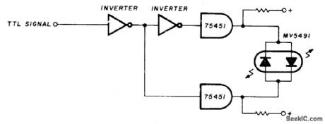
Level detector can be used with TTL, DTL, and RTL, as probe for troubleshooting. Indicator is Monsanto MV5491 dual red/green LED, with 220 ohms in upper lead to +5 V supply and 100 ohms in lower +5V lead because red and green LEDs in parallel back-to-back have different voltage re quirements. Will furnish green indication on high or plus signal and red indication on low or false signal. Supply voltage of +5 V can be taken from equipment under test. Circuit requires SN75451 driver ICs and two sections of SN7404 hex invelter.-K. Powell, Novel Indicator Circult, Ham Radio, April 1977, p 60-63. (View)
View full Circuit Diagram | Comments | Reading(892)
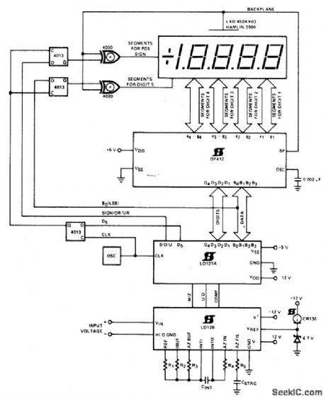
4_1_2_DIGIT_LCD_DVM
Published:2009/7/2 21:13:00 Author:May
View full Circuit Diagram | Comments | Reading(1649)
ECL_INTERFACE_FOR_LED
Published:2009/7/2 20:35:00 Author:May
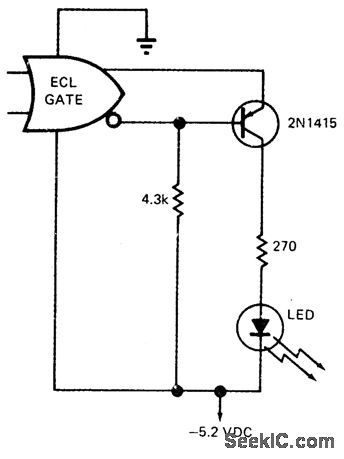
PNP germanium transistor serves as interface for driving LED from emitter-coupled logic. Same interface can be used to drive 7-segment or other arrays that have common-cathode configuration, such as Fairchild FND10 or Monsanto MAN3. Optoisolator can be used in place of LED.-G. A. Altemose, One Transistor Provides ECL to LED lnterface, EDN Magazine, Oct. 15, 1972, p 54, (View)
View full Circuit Diagram | Comments | Reading(812)
HIGH_CURRENT_INFRARED_LED_PULSER
Published:2009/7/2 2:10:00 Author:May
Circuit operates as regenerative amplifier for delivering 10-μs pulses with amplitude of 1.1 A and repetition rate of 1.4 kHz to infrared LED. Suitable for infrared beacon in fiber-optic communication and optical radar applications. Drain is 100 mA from 10-V supply. Use gallium arsenide LED such as SSL-55C or TIL32 for high-output infrared transmitter. Q2 can be changed to ger manium transistor such as 2N1305 to give peak current of 2 A at pulse width of 15 μs and 750-Hz repetition rate.-F. M Mims, Electronic Circuitbook 5: LED Projects, Howard W. Sams, Indianapolis, IN, 1976, p 33-35. (View)
View full Circuit Diagram | Comments | Reading(1453)
TRANSMISSION_INDICATOR
Published:2009/7/2 2:10:00 Author:May
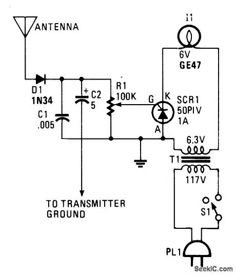
Everytime the push-to-talk button is closed the light will go on. The antenna samples the output RF from the transmitter. That signal is then rectifted (detected) by germanium diode D1, and used to charge capacitor C2. The dc output is used to trigger a small siliconcontrolled rectifier (SCR1), which permits the current to flow through the small pilot lamp. For lower-power applications, such as CB radio, the antenna will have to be close-coupled to the antenna. (View)
View full Circuit Diagram | Comments | Reading(853)
BASIC_MONO_DRIVES_LED
Published:2009/7/2 0:31:00 Author:May
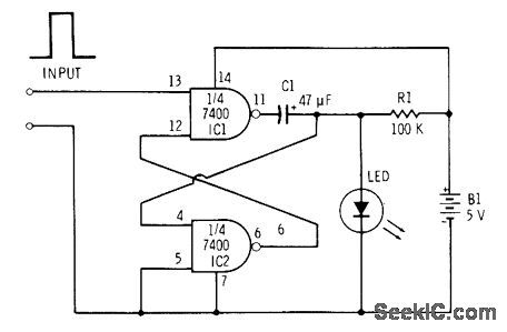
Two sections of 7400 quad NAND gate are connected as monostable MVBR having one stable state and one unstable state. Incoming pulse at pin 13 changes state of gate IC1. Since output of this gate goes to input of other gate, that also changes state. After interval determined by values of C1 and R1, gates automatically return to original states. LED flashes when input pulse is applied, for duration also determined by R1 or C1. If C1 is increased to 470μF, LED will stay on for over 1 s before fading out gradually as capacitor discharges.-F. M. Mints, Integrated Circuit Projects, Vol. 2, Radio Shack, Fort Worth, TX, 1977, 2nd Ed., p 19-26. (View)
View full Circuit Diagram | Comments | Reading(1493)
STROBING_LED_DISPLAY_1
Published:2009/7/1 23:56:00 Author:May
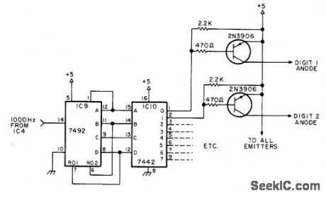
Sequential strobing of individual LED displays, at rate fast enough to eliminate flicker (about 10% duty cycle), cuts power requirements of LEDs and eliminates need for power-wasting resistors in series with digit segments. Circuit uses 7492 binary counter connected to divide by 10, continuously clocked by 1000-Hz signal from external counter time base. Each of the 10 counter states is decoded by 7442 decoder for use in turning on PNP switch transistor connected in series with anode of each 7-segment LED digit. Digits are thus turned on fol 10'/0 of time at 100-Hz rate.-B. Hart, Current-Saver Counter Display, 73 Magazine, June 1977, p 174-176. (View)
View full Circuit Diagram | Comments | Reading(1445)
LED_DIMMER
Published:2009/7/1 23:49:00 Author:May
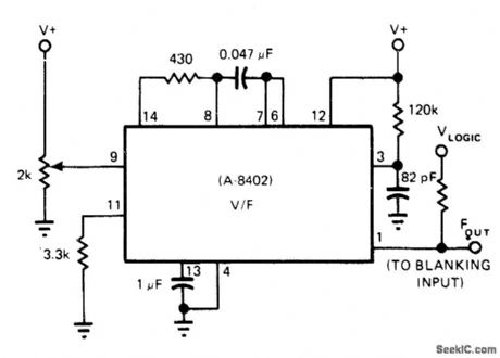
Intech/Function Modules A8402 is used in voltage-to-frequency mode to provide controllable dimming of LED display by varying frequency of blanking input to display driver. Display is pulsed on and off rapidly; the higher the duty cycle, the brighter the display.At highest input voltage the converter is forced out of linear region, making its mono remain on continuously for brightest display,-P. Pinter and D. Timm, Voltage-to-Frequency Converters-IC Versions Perform Accurate Data Conversion (and Much More) at Low Cost, EDN Magazine, Sept. 5, 1977, p 153-157. (View)
View full Circuit Diagram | Comments | Reading(876)
10O_LED_SOLID_STATE_OSClLLOSCOPE
Published:2009/7/1 23:18:00 Author:May
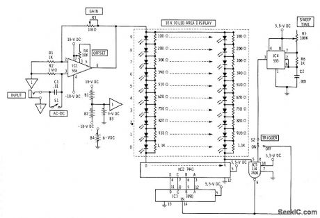
Flat display of LEDs replaces cathode-ray tube of oscilloscope. Suitable for classroom demonstrations even though resolution is poor. Amplified input signal is fed to upper ends of all ten vertical columns of LEDs. Under control of time base, scanner completes circuit at bottom of each column in turn. Vertical columns are made voltage-sensitive by resistors paralleling LEDs.Gate circuit using section of 7400 provides triggering when desired. Vohage-sensitive bargraph readouts formed by vertical columns are scanned by 7490 decade counter and 7441 decoder. Sweep rate of display is adjustable from 1 to 20 vertical columns per second with R5.-F,M Mims, Electronic Circuitbook 5: LED Projects, Howard Sams,Indianaplis,IN,1976,p 92-96. (View)
View full Circuit Diagram | Comments | Reading(2997)
JFET_ac_COUPLED_INTEGRATOR
Published:2009/7/1 23:16:00 Author:May
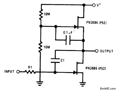
This circuit utilizes the μ-amp technique to achieve very high voltage gain. Using C1 in the circuit as a Miller integrator, or capacitance multiplier, allows this simple circuit to handle very long time constants. (View)
View full Circuit Diagram | Comments | Reading(1293)
31_2_DIGIT_MULTIPLEXED_LCD
Published:2009/7/1 23:15:00 Author:May
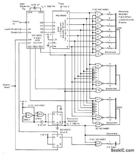
Uses MLC401 field-effect liquid crystal display, which is more suitable for multiplexing than dynamic-scattering LCD. Counters, latches, multiplexet, and scan circuits are all inMC14553 3-digit BCD counter whose outputs feed MC14543 decoder and driver for display. Excitation frequency of 100 Hz is derived from square-wave oscillator G1-G2 having exactly 50% duty cycle. Scan frequency is about 500 Hz, giving display refresh rate of 170 Hz, which is well beyond detectable flicker rate.-A. Pshaenich, Interface Considerations for Numeric Display Systems, Motorola, Phoenix, AZ, 1975, AN-741, p 6. (View)
View full Circuit Diagram | Comments | Reading(1552)
SIMULATED_INDUCTOR
Published:2009/7/1 23:07:00 Author:May
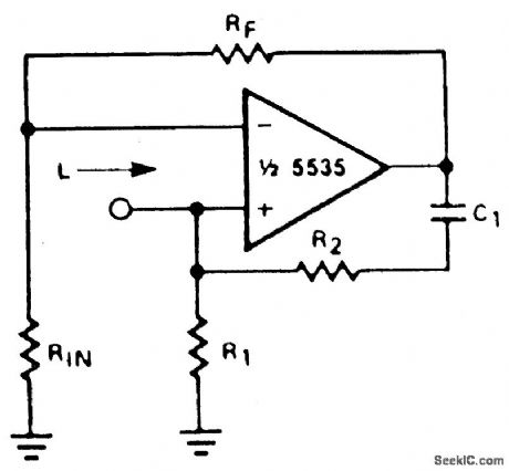
With a constant current excitation, the voltage dropped across an inductance increases with frequency. Thus, an active device whose output increases with frequency can be characterized as an inductance. The circuit yields such a response with the effective inductance being equal to: L= R1R2C. The Q of this inductance depends upon Ry being equal to R2. At the same time, however, the positive and negative feedback paths of the amplifier are equal leading to the distinct possibility of instability at high frequencies. R1 should therefore always be slightly smaller than R2 to assure stable operation. (View)
View full Circuit Diagram | Comments | Reading(0)
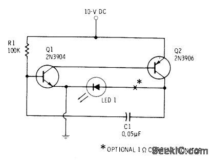
PULSED_LED
Published:2009/7/1 22:42:00 Author:May
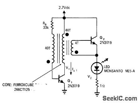
Circuit can generate peak currents above 1 A with pulse widths greater than 10 ms at repetition rates of 12 kHz with efficiency better than 90%, for 100-mA current drain from 2.5-V battery. Rise time of pulses is 0.2 ms. Can be used in low-light-level TV systems where high peak radiation gives better resolving power than constant illumination having same average power. Also useful for LED pilot lamps in battery-operated equipment and as lowpower strobe for studying mechanical motions.-J. Dimitrios, Current-Pulse Generator for LED's, EDN/EEE Magazine, July 1, 1971, P 51. (View)
View full Circuit Diagram | Comments | Reading(1203)
TWO_COLOR_LED
Published:2009/7/1 22:33:00 Author:May
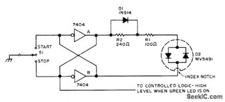
Dual LED D2 shows green when normally off momentary switch S1 is moved to START and shows red when moved to STOP. Latching circuit using two 7404 TTL inverters setves as run and haltflip-flop and also debounces switch. Momentary contact at START toggles latch, biasing green LED, D1 shorts R2, leaving R1 to limit forward current to about 20 mA for green, R1 and R2 limit current for D1 and brighter red LED to about 10 mA for momentary contact at STOP.-E. W. Gray, LEDs Light Up Your Logic, BYTE, Feb. 1976, p 54-57. (View)
View full Circuit Diagram | Comments | Reading(2141)
VACUUM_FLUORESCENT_DISPLAY
Published:2009/7/1 22:06:00 Author:May
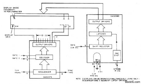
This circuit uses the CA3207 sequence driver and CA3208 segment latch-driver in combination to drive display devices of up to 14 segments with up to 14 characters of display. The CA3207 selects the digit or character to be displayed in sequence, CA3208 turns on the required alphanumeric segments. (View)
View full Circuit Diagram | Comments | Reading(1263)
PENDULUM_DISPLAY
Published:2009/7/1 22:05:00 Author:May
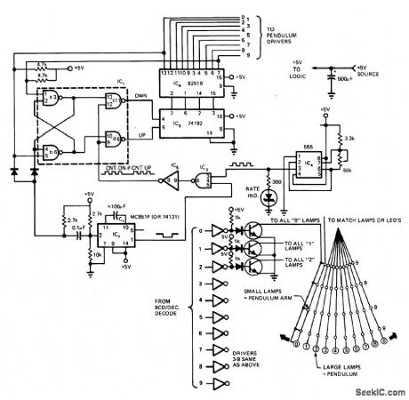
Ten series rows of LEDs or Christmas-tree Iights mounted behind diffused plastic are energized sequentially left to right,then right to left by counter-driven drivers to create illusion of bwinging pendulum. Circuit includes provision for pause at each change of direction, as in actual pendulum of clock. Article aces operation ol circuit in detail.-E. A. Flynn, Put a Pendulum in Your Electronic Grandfather Clock, EDN Magazine, May 5, 1975, p 88 and 90. (View)
View full Circuit Diagram | Comments | Reading(1835)
HI_L0_LED_FREQUENCY_DISPLAY
Published:2009/7/1 22:03:00 Author:May
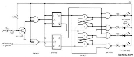
Apparent rotation of flashing LEDs around square indicates whether input frequency is above or below reference frequency. Input and reference waveforms may have any shape, because Schmitt triggers reshape both to give rectangular pulses which flip-flops divide by two so outputs are square waves with mark-space ratios at half original frequency. Squarewaves are gated together to produce rectangular pulse train having mark-space ratio that depends on phase difference between the two square waves.Logic is arranged to drive LEDs at rotation rate of half the difference between input and referencefrequencies. Correct positioning of LEDs in square is shown on small diagram.Reference frequency input should be via BC108B (not shown), same as for input frequency.-C. Clapp, Beat-Frequency Indicator, Wireless World, Nov. 1976, p 63. (View)
View full Circuit Diagram | Comments | Reading(1093)
OCTAL_DISPLAY
Published:2009/7/1 21:47:00 Author:May
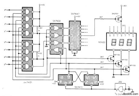
Circuit provides display of 8-bitdata word in conventional octal form forconvenience in experimentation with microprocessors and small computers. Three-state counter built around synchronously operated JK flip-flops provides digit and data selection. The two or threq bits appropriate to each display are steered to 7-segment decoder by wired-AND gates and inverters. Oscillator multiplexing frequency is about 2 kHz.-R. D. Mount, Octal Display for Microprocessors, Wireless World, March 1977, p 41. (View)
View full Circuit Diagram | Comments | Reading(2880)
SI_ABBREVIATION___DISPLAY
Published:2009/7/1 21:43:00 Author:May
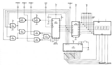
Programmed Signetics 8223 256-bit PROM is used as alphameric display having five 7-segment digits connected to form alphameric simulation of abbreviations for second, millisecond, microsecond, hertz, kilohertz, and megahertz as SEC, SEC-3, SEC-6, H2, H2 3, H2 6. Binary counter U3, 4-16 line decoder, and 5-digit parallel-connected Hewlett.Packard display form simple multi-plexer that addresses memory U4 one word at a time. External 1000-Hz square-wave oscillator drives counter and sets scanning rate. Requires only one 5-V supply. Article gives truth table for memoryand circuit for programmer required to set it up.-J.W,Springer,Function/Units Indicator Using LED Displays,Ham Radlio, March 1977,p 58-63. (View)
View full Circuit Diagram | Comments | Reading(2248)
| Pages:49/72 At 204142434445464748495051525354555657585960Under 20 |
Circuit Categories
power supply circuit
Amplifier Circuit
Basic Circuit
LED and Light Circuit
Sensor Circuit
Signal Processing
Electrical Equipment Circuit
Control Circuit
Remote Control Circuit
A/D-D/A Converter Circuit
Audio Circuit
Measuring and Test Circuit
Communication Circuit
Computer-Related Circuit
555 Circuit
Automotive Circuit
Repairing Circuit