
LED and Light Circuit
Index 56
BAR_GRAPH_ROOM_TEMPERATURE_DISPLAY
Published:2009/6/24 4:20:00 Author:May
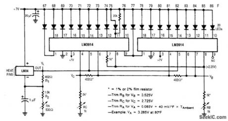
This display shows temperature as a bar graph. The range is 67°F to 86°F. (View)
View full Circuit Diagram | Comments | Reading(2375)
DISPLAY_BOARD_FOR_RADAR_GUN
Published:2009/6/24 3:17:00 Author:May
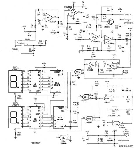
This circuit takes signal (doppler) from a radar,un, amplifies and limits it, and feeds the frequency into a counter (U4) and display circuit (DISP1, DISP2,U5,U6). Counter calibration is set by clock circuit U2B. Calibration is obtained via R21 and R22. R21 can be changed if kilometers/hour readout is desired. (View)
View full Circuit Diagram | Comments | Reading(3859)
MODEL_RAILROAD_CROSSING_FLASHER
Published:2009/6/23 4:27:00 Author:May

Gate U1-c is set up as an oscillator whose frequency is determined by C1 and R1. Gates U1-b and U1-d are set up as an RS flip-flop that is gated on by U1-a. Gate U1-a in conjunction with Q1 operates as the control gate for the flip-flop. Components D1, C2, and lR5 act as a delay circuit to compensate for anylight getting throughthe gaps between cars as theypass over the phototransistors. The light-emitting diodes are connected so that they operate alternately, depending on the outputs of U1-d and U1-b.Basically, R6 is adjusted so that ambient room-light striking Q1(and any other phototransistors connected in series)keeps the output of U1-a at pin 3 low. When a car passes over the phototransis-tor, which is installed between ties in the track, pin 3 goes high, allowing a high to be placed on pins 5 and 13. That allows the high output of UI-c at pin 10 to enable pin 12, which in turn allows pin 11 to go low. That makes a complete path for LED2 to operate. When pin 10 goes low, pin 11 goes high.That makes pin 5 high, and thus, enables pin 4 to go low and completes the circuit for LED1. That alternates the LEDs, which are installed in a railroad-crossing signal. (View)
View full Circuit Diagram | Comments | Reading(2223)
Drive LED Circuit of Voltage Dropping Model DC/DC Converter
Published:2011/7/23 8:23:00 Author:Michel | Keyword: DC/DC Converter, Drive LED Circuit
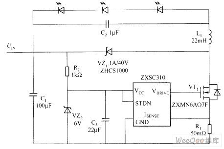
The dropping voltage model DC/DC converter drive LED circuit is showed as above.In this circuit,DC/DC converter(ZXSC310) works in dropping voltage model.More high system voltage can be provided by increasing the value of the R2 and the R2's value should be changed into 2.2kΩ if we want to get 24V voltage.At the same time capacitance C1 should also need the higher rated voltage. The circuit's basic work principle is as follows.When VT1 turns on, current flows through the white LED, capacitance and inductance L1 C1 .When both ends' voltage of R1 redcue to the threshold voltage of SENSE pin,VT1 shuts off and maintains a fixed time,the current in inductance flows through VZ and white LED.VT1 turns off again after the fixed time and the process repeats again and again.
Picture:Drive LED Circuit of Voltage Dropping Model DC/DC Converter (View)
View full Circuit Diagram | Comments | Reading(1053)
DELAYED_VIDEO_TRIGGER_FOR_SCOPES
Published:2009/6/23 2:49:00 Author:May
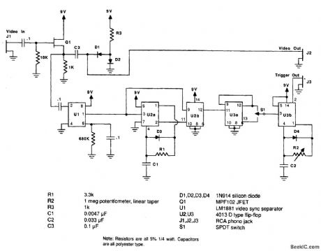
This circuit will extract vertical sync from a video signal, produce a vertical sync pulse, and add an adjustable delay. This permits a delayed sweep effect to enable a scope to look at any particular horizontal line. It is useful for older scopes. (View)
View full Circuit Diagram | Comments | Reading(1007)
Simple dimmer circuit diagram
Published:2011/7/28 2:12:00 Author:Ecco | Keyword: Simple dimmer
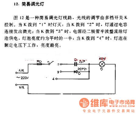
Simple dimmer
Figure 12 is a simple dimmer circuit, the adjustment of light is controlled by the multi-file switch K, when K sets to 1 , the lights are off; when the K sets to 2 , the light is shinedby the capacitor connecting; when K sets to 3 , the power is supplied to the lamp through the diode half-wave rectifier, the lamp's brightness is about half of usual; when the K sets to 4 , the light bulb works in the rated voltage, the brightness is brightest.
(View)
View full Circuit Diagram | Comments | Reading(798)
YOUR_NAME_IN_LIGHTS
Published:2009/6/23 2:16:00 Author:May
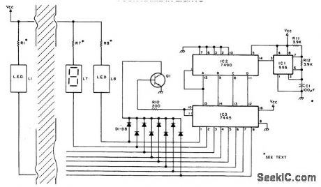
This circuit will enable you to put a name or callsign in lights using seven-segment LEDs. The display will spell the desired name out sequentially. Select the correct type of LED. Solder the cor-rect leads together to form the letters you want. After mounting the appropriate current-limiting re-sistor, the 7445 can only sink 80 mA, so a PNP transistor is needed to handle the current required to light the letters. The heart of the circuit is a 555 oscillator into a 7490 decade counter, which is de-coded by a 7445 open-collector driver chip. (View)
View full Circuit Diagram | Comments | Reading(757)
SWR_WARNING_INDICATOR
Published:2009/6/23 1:47:00 Author:May
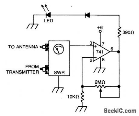
Op amp with dc input from SWR metercan be adjusted to preset the SWR reading at which the LED lights. (View)
View full Circuit Diagram | Comments | Reading(1702)
SELF_POWERED_CW_MONITOR
Published:2009/6/23 1:44:00 Author:May
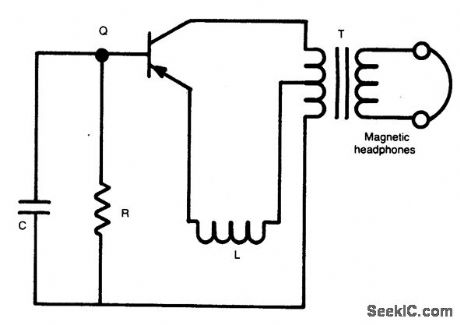
Position L near the transmitter output tank to hear the key-down tone。Then tape the coil In place. C=.047μF,R=8.2 K,Q=HEP 253(or equal),T=500:500 ohm center tapped transformer. L = 2 to 6 turns on 1/2'' coil from. (View)
View full Circuit Diagram | Comments | Reading(1160)
The differential light detecion circuit
Published:2011/7/21 2:55:00 Author:Seven | Keyword: light detecion circuit
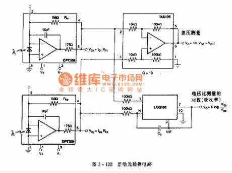
figure 2-120 The differential light detecion circuit (View)
View full Circuit Diagram | Comments | Reading(615)
The laser diode drive circuit
Published:2011/7/21 2:59:00 Author:Seven | Keyword: laser diode, drive circuit
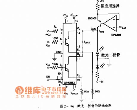
Figure 2-146. The laser diode drive circuit (View)
View full Circuit Diagram | Comments | Reading(814)
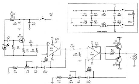
AF_DRIVE_INDICATOR
Published:2009/6/22 23:07:00 Author:May
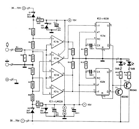
This circuit was used with an audio power amplifier to detect the point at which output is -3 dB from maximum, indicated by LED D5, and at clipping, shown by LED D6. The indicator can be used with any amplifier operating from a ±30 to ±70V symmetrical supply. (View)
View full Circuit Diagram | Comments | Reading(1035)
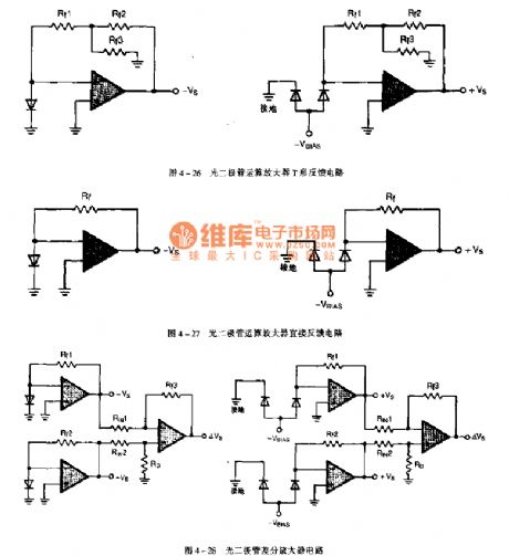
The photodiode application circuit
Published:2011/7/21 2:37:00 Author:Seven | Keyword: photodiode, application circuit
View full Circuit Diagram | Comments | Reading(1685)
The circuit diagram of Led lattice electronic shielding controled by PLC
Published:2011/7/21 3:06:00 Author:Ecco | Keyword: PLC, Led dots electron shielding
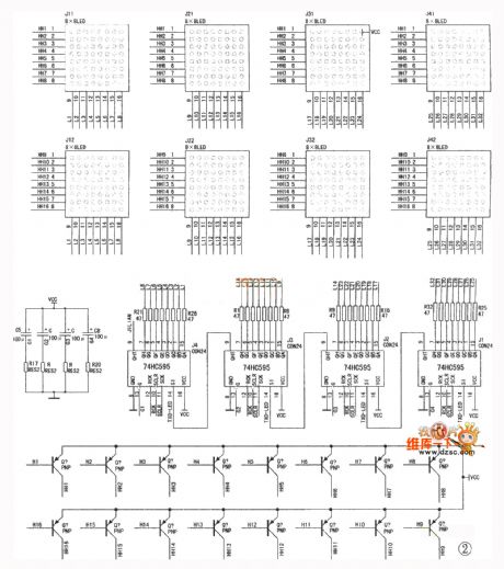
View full Circuit Diagram | Comments | Reading(952)
Photoelectric lighting circuit diagram
Published:2011/7/28 2:11:00 Author:Ecco | Keyword: Photoelectric lighting
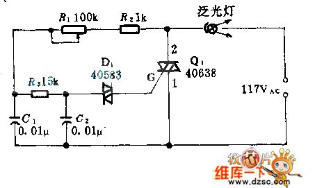
Influenced by bidirectional triode thyristor Q1 and disconnect rock, bidirectional switching LED D1, and potentiometer R1, the circuitry can connect 500w lamps, and the light could be turned on absolutely. Using a 5A rapid safety machine to connect lamps in series, it can avoid the current from breaking bidirectional Hiccup controlled silicon by the current at short circuit.
(View)
View full Circuit Diagram | Comments | Reading(974)
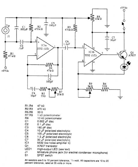
LED_LIGHTWAVE_RECEIVER
Published:2009/6/22 22:56:00 Author:May
View full Circuit Diagram | Comments | Reading(788)
FCC_PART_68_PHONE_INTERFACE
Published:2009/6/22 22:56:00 Author:May
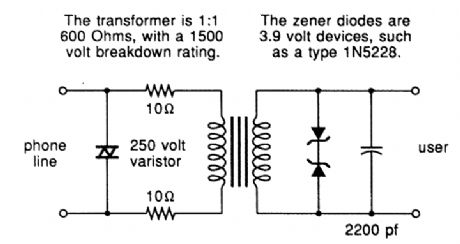
An FCC Part 68 interface is required any time you connect any circut of your own to the phone line. (View)
View full Circuit Diagram | Comments | Reading(747)
LED_LIGHTWAVE_COMMUNICATIONS_TRANSMITTER
Published:2009/6/22 22:55:00 Author:May
View full Circuit Diagram | Comments | Reading(949)
CALLER_ID_CIRCUIT
Published:2009/6/22 22:54:00 Author:May
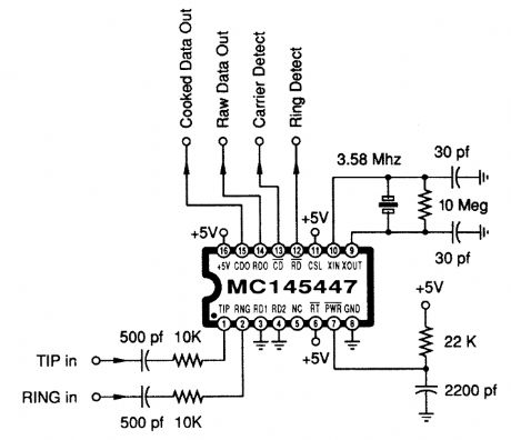
This caller ID circuit uses the Motorola MC145447 IC chip. This servlce must be available from your local phone company In order for this circuit to be used. (View)
View full Circuit Diagram | Comments | Reading(5446)
LIGHT_SWITCHED_LED_BLINKER
Published:2009/6/22 22:42:00 Author:May
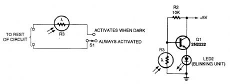
This circuit can be used to flash an LED during periods of darkness.Use it for burglar alarm simulators for boats,docks,autos,etc. (View)
View full Circuit Diagram | Comments | Reading(706)
| Pages:56/72 At 204142434445464748495051525354555657585960Under 20 |
Circuit Categories
power supply circuit
Amplifier Circuit
Basic Circuit
LED and Light Circuit
Sensor Circuit
Signal Processing
Electrical Equipment Circuit
Control Circuit
Remote Control Circuit
A/D-D/A Converter Circuit
Audio Circuit
Measuring and Test Circuit
Communication Circuit
Computer-Related Circuit
555 Circuit
Automotive Circuit
Repairing Circuit