
LED and Light Circuit
Index 57
BATTERY_CHARGE_INDICATOR
Published:2009/6/22 22:28:00 Author:May
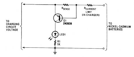
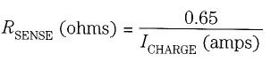
When a battery is charging, a voltage drop across RSENSE causes Q1 to conduct,and lights LED1. RSENSE should be chosen as follows:
(View)
View full Circuit Diagram | Comments | Reading(1422)
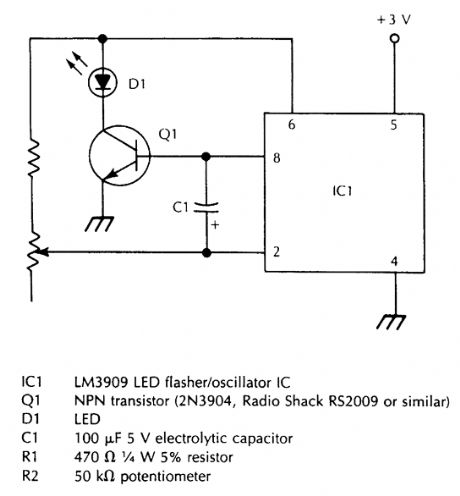
UNDERVOLTAGE_INDICATOR_FOR_SINGLE_CELL
Published:2009/6/22 22:22:00 Author:May
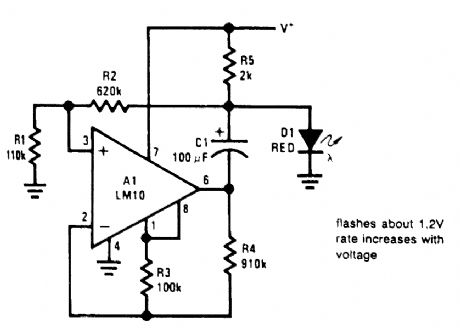
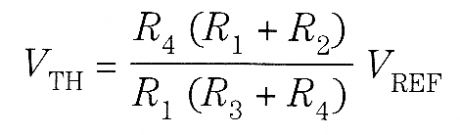
When operating with a single cell,it is necessary to incorporate switching circuitry to developsufficient voltage to drive the LED,A circuit that accomplishes this IS drawn In the figure shown Basically, it IS a voltage-cqntrolled asymmetrical multivibrator with a minimum operating thresholdgtven by∶ Above this threshold,the flash frequency increases with voltage This is a far more noticeable indication of a deteriorating battery than merely dimming the LED In addition,the indicator can bemade visible with considerably less power drain With the values shown,the flash rate is 1.4 sec -1at 1.2V with 300-μA drain and 5.5 sec-1 at 1.55V with 800-μA drain Equivalent visibility for continuous operation would require more than 5-mA drain. (View)
View full Circuit Diagram | Comments | Reading(769)
KEY_ILLUMINATOR
Published:2009/6/19 4:42:00 Author:May
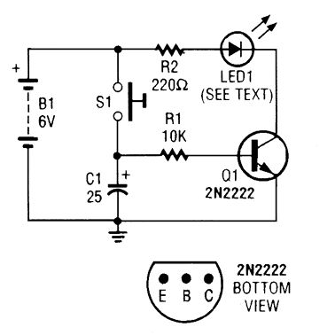
Used as a 10-second momentary illuminator, this circuit can be useful in other applications as well. Pressing S1 charges C1, which holds Q1 on and holds the LED lit for about 10 seconds. (View)
View full Circuit Diagram | Comments | Reading(872)
Buick headlamps circuit diagram (with the low beam control DRL)
Published:2011/5/6 1:40:00 Author:Jessie | Keyword: headlamps

View full Circuit Diagram | Comments | Reading(727)
LED_OUTPUT_INDICATOR_FOR_555_CIRCUITS
Published:2009/6/19 3:58:00 Author:May
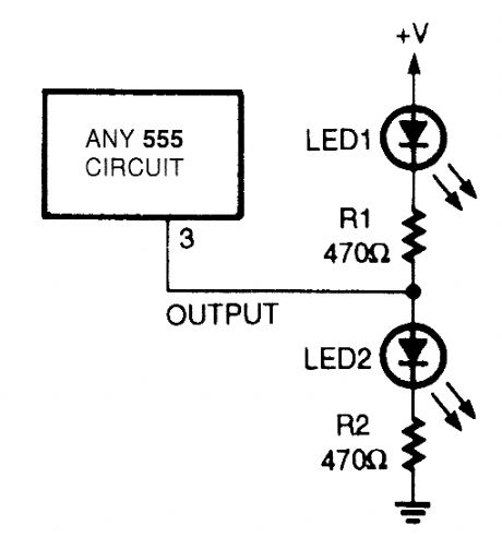
A pair of LEDs connected as shown here can be used with just about any low-frequency 555 os-cillator to give high-/low-output indications. When the output goes high LED2 turns on, and when the output goes low LED1 tums on. (View)
View full Circuit Diagram | Comments | Reading(823)
RECEIVER_SIGNAL_STRENGTH_INDICATOR
Published:2009/6/19 3:58:00 Author:May
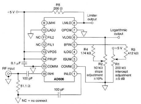
Using an AD606 log amplifier, this indicator gives a logarithmic output of +0.3 V at -80-dBm in-put to +3.5 V at 10-dBm input. Frequency range is to 50 MHz for this IC device. (View)
View full Circuit Diagram | Comments | Reading(1150)
CURRENT_INDICATOR
Published:2009/6/19 3:57:00 Author:May
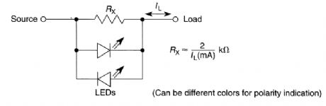
An LED requires 1.5 to 3 V across its terminals to light. This circuit uses a resistor shunt in series with source and load to produce this drop and cause the LED to Iight. At higher currents (>100 mA) use limiting resistors in series with LEDs to limit current to a safe value. (View)
View full Circuit Diagram | Comments | Reading(865)
MODEL_OAR_DERBY_WINNER_INDICATOR
Published:2009/6/19 3:56:00 Author:May
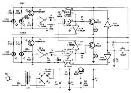
This derby-winner inc!icator uses infrared emitters and sensors to detect a car crossing the fintsh line. The first car to finish locks out the data from the second car, and the system can be reset by pressing S1. (View)
View full Circuit Diagram | Comments | Reading(806)
LEAD_ACID_TRIOKLE_CHARGER
Published:2009/6/19 3:10:00 Author:May
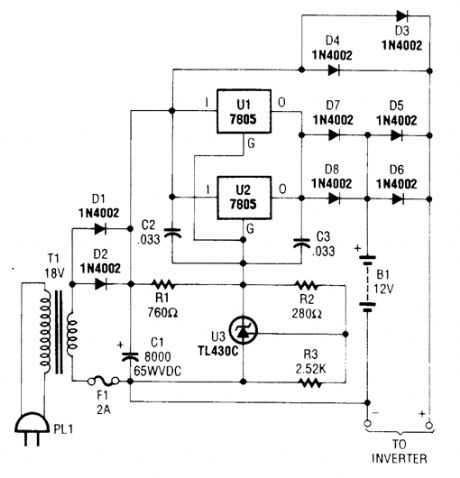
This lead-acid battery trickle charger can be used as a stand-alone circuit (for alarm systems and such) or combined with the circuit in the figure to create an emergency lighting system. (View)
View full Circuit Diagram | Comments | Reading(1273)
LED_FLASHER
Published:2009/6/19 2:52:00 Author:May
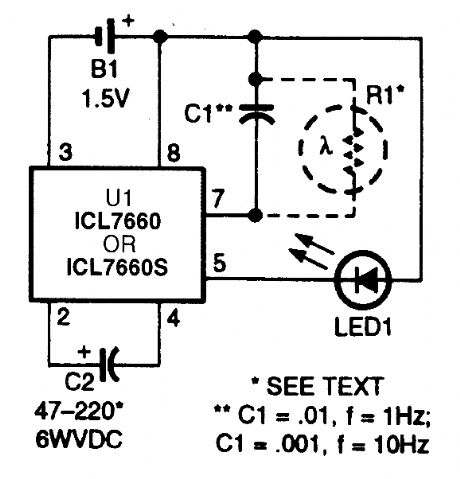
This circuit provides a low-cost way to flash an LED from a single 1.5-V source. Based on the ICL7660 dcto-dc voltage converter, the circuit makes use of an extemal capacitance (C1) on the os-cillator ratecontrol pin to decrease the charge/dump time to the desired flash rate. A dc resistance (R1) on the same pin can also be used to disable the oscillator and extend the power-cell's life. That optional dc resistance (in the form of a photoconductive cell) will shut off the oscillator in daylight. (View)
View full Circuit Diagram | Comments | Reading(3619)
LED_PULSER_WITH_AUDIBLE_OUTPUT
Published:2009/6/19 2:49:00 Author:May
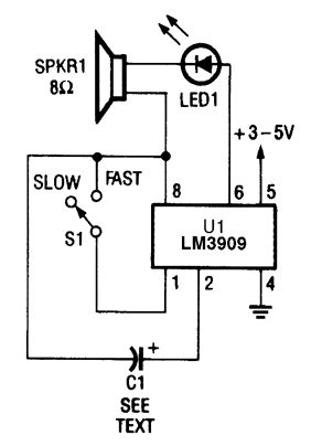
The LM3090 can also be used to drive both an LED and a speaker. In this circuit, each time that LED1 blinks, SPKR1 (an 8-Ω speaker) emits a sharp click sound. (View)
View full Circuit Diagram | Comments | Reading(1129)
LED_PULSER
Published:2009/6/19 2:48:00 Author:May
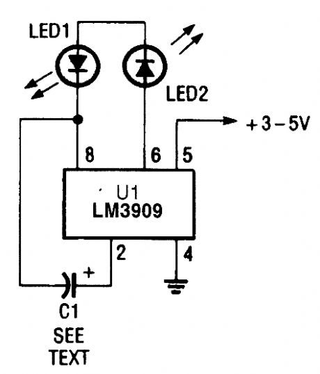
In this circuit, the LM3909 is used to drive a pair of series-connected LEDs. (View)
View full Circuit Diagram | Comments | Reading(2573)
VARIABLE_FREQUENCY_HIGH_POWER_LED_FLASHER
Published:2009/6/19 2:47:00 Author:May
View full Circuit Diagram | Comments | Reading(940)
RECHARGEABLE_LED_FLASHLIGHT
Published:2009/6/19 2:46:00 Author:May

This flashlight is useful for applications where night vision and/or darkness adaptation must be maintained. It uses an HLMP8150 T4 LED with a wavelength of 637 nm. This schematic is for the flashlight module. When the battery pack consisting of the four NiCad cells is fully charged (and there is no voltage at J1), 4.8 Vdc flows through trimmer potentiometer R2, the normally closed con-tact of relay RY1, and push-on/push-off power switch Al. Trimmer R2 limits the current flowing through LED1. Switch 51 can turn LED1 on and off when the battery is not being charged. (View)
View full Circuit Diagram | Comments | Reading(2362)
FLASHING_CHRISTMAS_LED_DISPLAY
Published:2009/6/19 2:43:00 Author:May
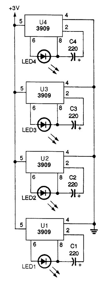
Using LEDs and 3909 ICs,you can make aflashing-light circuit that will run for months ontwo AA batteries. (View)
View full Circuit Diagram | Comments | Reading(790)
FLASHING_NEON_CHRISTMAS_LIGHTS
Published:2009/6/19 2:41:00 Author:May
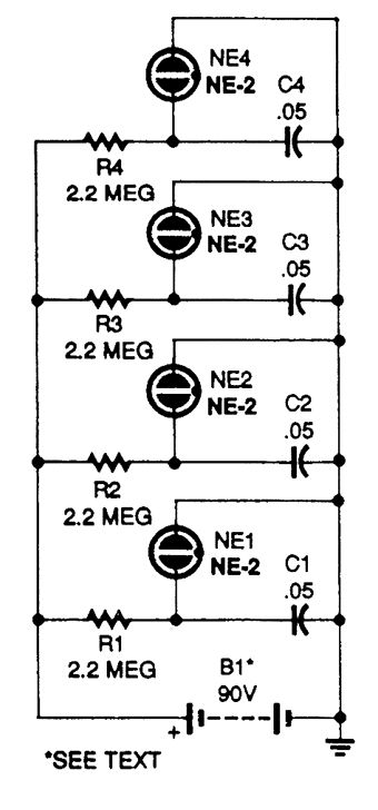
This flashing set of neon Christmas lights will make an attractive decoration for any time of year. B1 is made up of ten 9-V transistor radio batteries in series. The battery life can be measured in months. (View)
View full Circuit Diagram | Comments | Reading(972)
RANDOM_LED_STROBE
Published:2009/6/19 2:40:00 Author:May
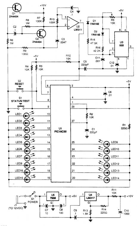
This circuit generates a random output that is translated into LED movement by a prepro-grammed PIC16C55 microcontroller, U1. That PIC also senses and records the bias of the LED's movement. This device was originally used for an application involving psychokinesis testing where the person was asked to think the lights in either a clockwise or counterclockwise direction. (View)
View full Circuit Diagram | Comments | Reading(3103)
HEADLIGHT_OFF_INDICATOR
Published:2009/6/19 2:37:00 Author:May
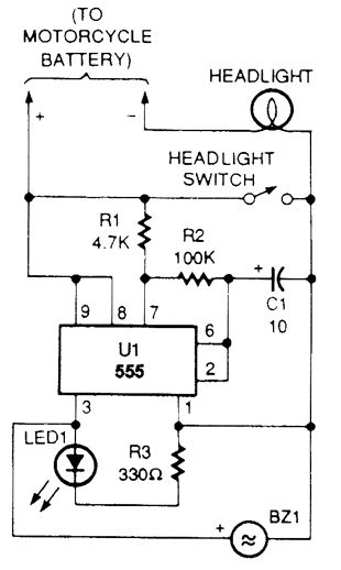
Increasing the value of R2 or C1 will lower the oscillator's frequency and decreasing one of those values will increase the frequency. The IC's output at pin 3 drives the LED through R3 and sends power to the piezo sounden Use a bright LED so that you will be able to see it in the daytime. (View)
View full Circuit Diagram | Comments | Reading(791)
Remote control type music color lamp circuit (2)
Published:2011/7/5 21:42:00 Author:zj | Keyword: Remote control type, music color lamp circuit
As shown in the diagram,the wire type music color lamp circuit candivide music signalinto high, medium and low three frequency bands, respectively drive the red, green, blue three colors lantern group with music flashing, can produce a riot of colours, colorful light. Available T transistor radio small input transformer ; inductance L homemade :use diameter of 1mm wire in a 25mmby 28mm insulating frame around the 200 windings. It will be fine. (View)
View full Circuit Diagram | Comments | Reading(837)
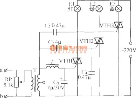
Remote control type music color lamp circuit (1)
Published:2011/7/5 21:49:00 Author:zj | Keyword: Remote control type, music, color lamp circuit

As shown in the figure it is a simple wire type music color lamp circuit. From the speaker at both ends of the audio frequency voltage through the wire connected to the A, B end, by the potentiometer RP partial pressure applied to the audio transformer T primary, audio voltage by T followed by a boost secondary to the bidirectional thyristor control VTH electrode and the second anode. When the audio frequency voltage is high, VTH opened, festoon lamp string E light; when the music stops or is weak enough to trigger the VTH, VTH in alternating current crosses zero is turned off. Therefore, the lamp string E brightness flickers with horn playing music rhythm. Regulating potentiometer RP value can modulate circuit wire sensitivity; T canadoptsmall input transformer in transistor radio. (View)
View full Circuit Diagram | Comments | Reading(772)
| Pages:57/72 At 204142434445464748495051525354555657585960Under 20 |
Circuit Categories
power supply circuit
Amplifier Circuit
Basic Circuit
LED and Light Circuit
Sensor Circuit
Signal Processing
Electrical Equipment Circuit
Control Circuit
Remote Control Circuit
A/D-D/A Converter Circuit
Audio Circuit
Measuring and Test Circuit
Communication Circuit
Computer-Related Circuit
555 Circuit
Automotive Circuit
Repairing Circuit