
Battery Charger
Index 13
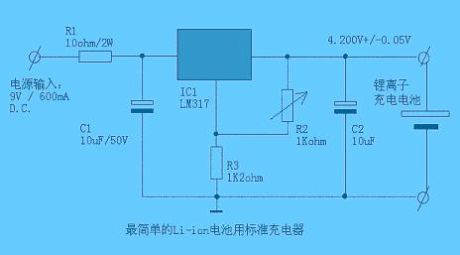
Simpleset standard Li-ion battery charger
Published:2011/4/20 6:34:00 Author:May | Keyword: Li-ion battery charger
View full Circuit Diagram | Comments | Reading(1279)
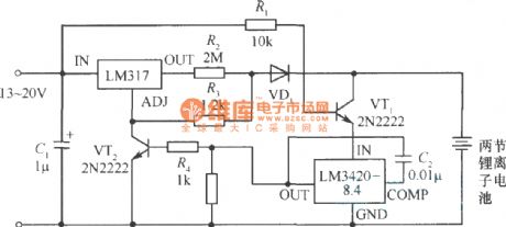
Li-ion battery charger circuit diagram
Published:2011/4/19 8:46:00 Author:May | Keyword: Li-ion battery charger
View full Circuit Diagram | Comments | Reading(4797)
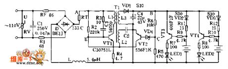
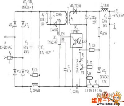
Simple and practical Li-ion battery charger
Published:2011/4/19 8:17:00 Author:May | Keyword: Simple, practical, Li-ion battery charger
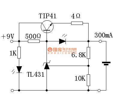
Brief descriptions: You can home make a simple and pracitcal Li-ion battery charger. It can change the charge current by changing 4Ω resistor. D1 is power supply indication. D2 is charging indication and current limitting.Simple and practical Li-ion battery charger
When debugging, 6.8K resistor can replace by a 10K trimming resistor. It is Using digital meter to monitor the battery voltage. When the battery voltage is 4.2V, you can adjust the 10K trimming resistor.
(View)
View full Circuit Diagram | Comments | Reading(11520)
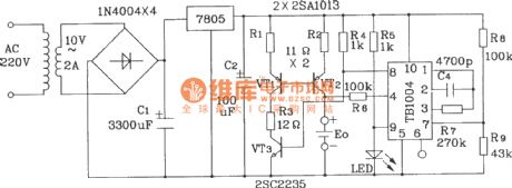
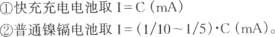
Ni-Cd battery charge circuit composed of TB1004 charge control integrated circuit
Published:2011/4/18 21:06:00 Author:Nicole | Keyword: Ni-Cd battery, charge control

(View)
View full Circuit Diagram | Comments | Reading(886)
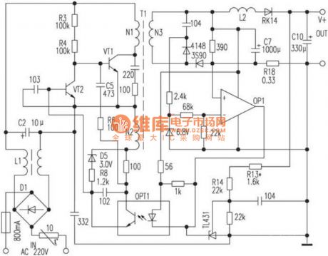
Jinniu charger circuit
Published:2011/4/18 2:36:00 Author:May | Keyword: Jinniu, charger
View full Circuit Diagram | Comments | Reading(846)
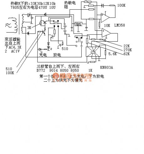
Ni-Cd battery charging circuit
Published:2011/4/14 22:11:00 Author:Nicole | Keyword: Ni-Cd battery
In the circuit, R1 is 10Ω, R2 is 200Ω. When the switch is up closed, the charging current is 60mA(constant current); when the switch is down closed, the charging current is 3mA(constant current). The total pressure drop of silicon diodes CR1, CR2 is 1.2V, and the Q1 emitter pressure drop is 0.6V, so the net pressure drop on R1 or R2 is 0.6V. 0.6V divided by the required charging current (using ampere), then it is the resistance of R1 or R2. LED indicates the work state of this charging circuit. (View)
View full Circuit Diagram | Comments | Reading(1170)
Adjustable integrated regulated power supply standard circuit
Published:2011/4/11 2:11:00 Author:Nicole | Keyword: regulated power supply
View full Circuit Diagram | Comments | Reading(718)
SANYO NC-5 charger circuit diagram
Published:2011/4/1 3:39:00 Author:Nicole | Keyword: charger
View full Circuit Diagram | Comments | Reading(1414)
600mA Single lithium battery charging circuit diagram
Published:2011/4/2 4:05:00 Author:Rebekka | Keyword: 600mA Single lithium, battery charging

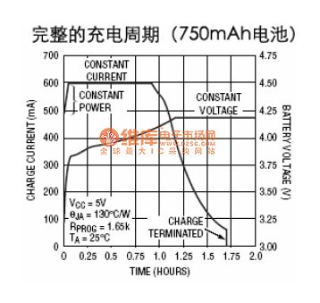
HYM4054 model itself afterLinear Technology's LTC4054 . It is suitable for USB charging. Themaximum charge current is800mA.
(View)
View full Circuit Diagram | Comments | Reading(1182)
MAX1811 USB mobile phone emergency charger circuit diagram
Published:2011/4/2 4:02:00 Author:Rebekka | Keyword: USB mobile phone emergency charger
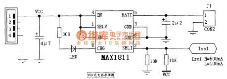
MAX1811 USB mobile phone emergency charger circuit diagram is shown as below.
(View)
View full Circuit Diagram | Comments | Reading(4877)
10A Auto battery charger circuit diagram
Published:2011/4/2 4:00:00 Author:Rebekka | Keyword: Auto battery charger
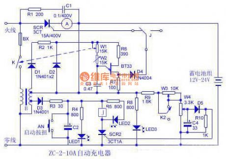
10A Auto battery charger circuit diagram is shown as below.
(View)
View full Circuit Diagram | Comments | Reading(5567)
Electric bicycle 36v battery charger circuit diagram
Published:2011/4/2 3:59:00 Author:Rebekka | Keyword: Electric Bicycle, Battery Charger
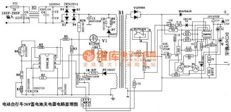
The Electric Bicycle 36V Battery Charger Circuit Diagram is shown as below.
(View)
View full Circuit Diagram | Comments | Reading(20682)
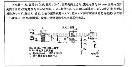
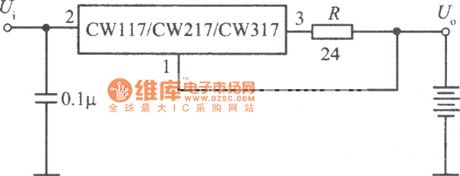
Constant current battery charger circuit consisting of CW117
Published:2011/3/31 4:25:00 Author:Joan | Keyword: Constant current battery charger
View full Circuit Diagram | Comments | Reading(798)
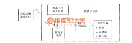
Lithium ion battery charging and system load power up schematic diagram
Published:2011/4/7 2:39:00 Author:Nicole | Keyword: lithium ion battery, charging, system load
View full Circuit Diagram | Comments | Reading(950)
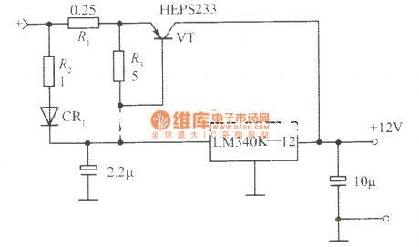
12V、10A regulated power supply composed of LM340K-12
Published:2011/4/6 0:47:00 Author:Nicole | Keyword: regulated power supply
View full Circuit Diagram | Comments | Reading(1813)
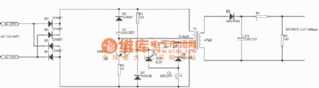
Cell phone battery constant-current charger circuit diagram
Published:2011/3/29 20:05:00 Author:Ecco | Keyword: Cell phone battery , constant-current, charger
Cell phone battery constant-current charger circuit diagram is as below:
(View)
View full Circuit Diagram | Comments | Reading(3239)
Mini Switch Power Charger Circuit Diagram
Published:2011/3/21 1:49:00 Author:Rebrecca | Keyword: Mini Switch, Power Charger
The Mini Switch Power Charger Circuit Diagram is shown as below.
(View)
View full Circuit Diagram | Comments | Reading(1085)
LM135 Ni-Cd battery fast charging circuit
Published:2011/3/21 0:52:00 Author:Joan | Keyword: Ni-Cd battery, fast charging
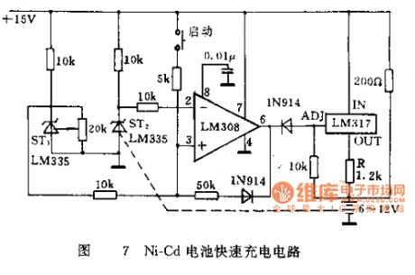
The figure is a safe and reliable Ni-Cd battery fast charging circuit. It detects the completion of battery chargeusing Ni-Cd battery case temperature change. In general, it has been already charge 80% of rated capacity when the rechargeable battery temperature rises to 5 ℃. ST1 is used to detect the ambient temperature, ST2 thermal coupled the rechargeable battery are used to detect the battery temperature. The offset terminal of the temperature sensor adjust ST1 output voltage 50mV higher than that of ST2. When the battery temperature exceeds 5 ℃ of the ambient temperature, the comparator LM308 output goes low, LM317change from constant current source state to the voltage source state, the output voltage is only about 2V, Power supply continues to charge the battery only through the R by 50mA small current. The method can save time and will not overcharge.
(View)
View full Circuit Diagram | Comments | Reading(1831)
Mobile phone charger circuit diagram
Published:2011/3/21 1:42:00 Author:Rebrecca | Keyword: Mobile phone charger
The mobile phone charger circuit diagram is shown as below. (View)
View full Circuit Diagram | Comments | Reading(2278)
| Pages:13/13 12345678910111213 |
Circuit Categories
power supply circuit
Amplifier Circuit
Basic Circuit
LED and Light Circuit
Sensor Circuit
Signal Processing
Electrical Equipment Circuit
Control Circuit
Remote Control Circuit
A/D-D/A Converter Circuit
Audio Circuit
Measuring and Test Circuit
Communication Circuit
Computer-Related Circuit
555 Circuit
Automotive Circuit
Repairing Circuit