
Battery Charger
Index 2
Industrial Battery Charger Project Kit
Published:2013/3/27 4:23:00 Author:Ecco | Keyword: Industrial, Battery Charger, Project Kit
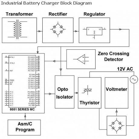
The assignment is intended for charging battery(s) by DC from AC supply of power. DC power supplied for a battery’s charger is a derivative from a thyristor controlled rectifier mechanism. AC supply of power is useful to a link rectifier consisting of diodes and a TRIAC achieving preferred power from the micro controller.
(View)
View full Circuit Diagram | Comments | Reading(1757)
Simple 12 Volt Battery charger
Published:2013/3/22 4:02:00 Author:Ecco | Keyword: 12 Volt Battery charger
This kind of battery charger circuit will quickly and easily recharge almost every lead acid battery pack.This battery charger supplies maximum current till the current drawn by the battery falls to 150 miliamper. At this point, less voltage will be applied to complete and avoid over charging. Once the lead acid battery is completely charged, this circuit goes off and lights up the led, showing that the battery has completed to be charged.
(View)
View full Circuit Diagram | Comments | Reading(2951)
Mobile Charger with Voltage Converter
Published:2013/3/22 4:00:00 Author:Ecco | Keyword: Mobile Charger , Voltage Converter
The circuit allows a simple and safe charging of 1-10 Ni-Cd or Ni-MH cells from a 12V source. The voltage converter can be operated at 6V, in this case is the max. output voltage 12V (no load). The performance can be improved through the use of Schottky diodes (D2/D3). D4 (LED) can omitted if you dont want any indicator. An astable Mutivibrator generates the oscillation frequency. At the output (pin 3) connected the voltage doubler. At C5 is idling roughly double the input voltage. Thus, sufficient voltage difference exists to charge the connected batteries.Due to the high Switching frequency can be used relatively small capacitors. The charge current is indicated by a “real” load control (D4).
(View)
View full Circuit Diagram | Comments | Reading(1761)
12 Volt Battery charger
Published:2013/3/22 3:58:00 Author:Ecco | Keyword: 12 Volt, Battery charger
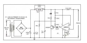
The following schematic is a high-performance battery charger for gelled electrolyte lead acid battery. Battery charger quickly recharges lead acid battery and shuts off at a full charge. Innitially, charging current has limitations to 2 Ampere. While the battery voltage goes up, current to the lead acid battery decrease, and if the current has decrease to 150 mA, the battery charger changes to a lower float voltage protecting against overcharge.
(View)
View full Circuit Diagram | Comments | Reading(1838)
5 A Stable Car Baterry Charger
Published:2013/3/22 3:39:00 Author:Ecco | Keyword: 5 A , Stable Car Baterry Charger
View full Circuit Diagram | Comments | Reading(2486)
60 Watt Laptop Battery Charger
Published:2013/3/22 3:02:00 Author:Ecco | Keyword: 60 Watt , Laptop Battery Charger
The circuit is designed for laptop battery charger with 20V output voltage. This circuit uses TOP 246 Y made by Power integrations. TOP 246 Y eliminates half the discrete components compared with the UC3842. As promised Power Integration, this IC is more reliable, has a smaller form, reducing the time in designing and saving costs.
(View)
View full Circuit Diagram | Comments | Reading(2399)
Charger for All Battery Types
Published:2013/3/22 2:58:00 Author:Ecco | Keyword: Charger, All Battery Types
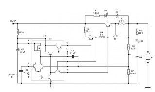
Note that the stability is observed when the load current and will change slightly of the supply voltage. Likewise, the fact is usually overlooked, but if you want a perfect stability – stabilize the power supply. Calculation of the current is very simple – the current in amperes is equal to 1.2 divided by the resistance R1 in Ohms. To display the current used transistor (germanium necessarily because of the low voltage opening) that allows you to visually observe the currents to 50 mA.
Diode D1 and F2 fuse protects the charger from the battery reverse. Capacitance C1 is selected from the formula: 1 amp should 2000uF.
The advantages of the proposed device: short-circuit protected it does not matter the number of elements in rechargeable battery and type – can be charged and sealed acid and lithium 12.6 3.6 and 7.2 V alkaline Switch current should be included exactly as shown on the chart – in order to remain in any manipulation of the resistor R1. The use of alternating low-impedance resistor is undesirable because of instability of sliding contact with load currents over 0.2 A.
(View)
View full Circuit Diagram | Comments | Reading(2123)
Charger for NiCd Batteries
Published:2013/3/22 2:12:00 Author:Ecco | Keyword: Charger, NiCd Batteries
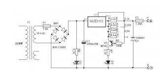
This device is used to simultaneously charge for Ni-Cd batteries. The output step-down transformer AC 12V is fed to the rectifying diode bridge, assembled on a 4-diode 1N4007. Smooth capacitor C3 constant voltage supplied to the chip 7808 , the output of which will be regulated voltage 8 V. The transistor T1 ( BC547 ), incorporated on the emitter follower circuit is used as a voltage regulator, which determines the charge current.
The magnitude of this current can be adjusted by potentiometer VR2, or use a switch with three trimmer, each of which is exposed to the desired charge current (90 mA, 180 mA and 300 mA). (The figure lower conclusions potentiometer must be connected). If you want to have the batteries recharged very quickly, select the charge current of 300 mA, the charging time is about 30 minutes. Light-emitting diodes LED1 … LED4 are indicators of the charge, they shine only when a battery charging current flows. On transistors T2 … T5 made permanent sources of charging current. The integrated regulator IC1, install the heat sink.
(View)
View full Circuit Diagram | Comments | Reading(1863)
5 volt Charger based LNK616PG Chip
Published:2013/3/22 2:10:00 Author:Ecco | Keyword: 5 volt Charger, Chip
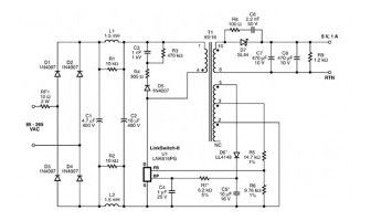
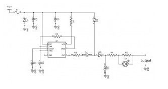
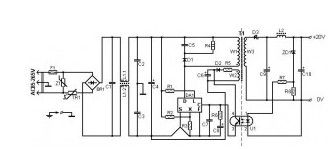
On-chip LNK616PG of LinkSwitch-II family firms Power Integrations can be designed very simple battery charger with mains supply, which can operate in either stabilizing the voltage and current stabilization mode. The device can be used for charging mobile phones or other electronic devices that consume less than 5 watts.
LNK616PG chip was developed for use in the budget of low-voltage chargers and network adapters. This controller provides precise control of output voltage and current for a small number of external components, and characteristically, without the use of optocouplers.
(View)
View full Circuit Diagram | Comments | Reading(1068)
Charger for Li-ion battery based LP2951
Published:2013/3/22 2:03:00 Author:Ecco | Keyword: Charger , Li-ion battery
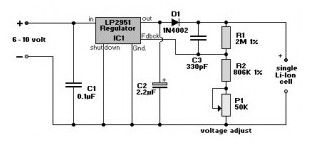
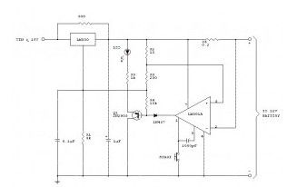
Stabilizer LP2951 manufactured by National Semiconductors. Element values are taken from the article “Charging”, written by Chester Simpson.
Diode D1 can be any of a series of 1N400x, which can be purchased. It is used as a lock, to prevent reverse current from the battery to the chip LP2951 when disconnecting the input voltage.
The current charge is about 100 mA, and this value is the maximum current is limited to the internal circuits chips LP2951. For those who are interested, let us explain that any lithium-ion battery can be recharged up to charge current 1C (ie, the current in mA equivalent capacity in mAh, so that, for example, the battery capacity of 1100 mAh can be recharged current to 1100 mA). The lower charge current leads, respectively, to more charge time. In my humble opinion, 100 mA – relatively low charging current, so that the typical lithium-ion battery can be connected to this charger for the night.
(View)
View full Circuit Diagram | Comments | Reading(1750)
Car charger for Nicd Battery Packs
Published:2013/3/21 4:15:00 Author:Ecco | Keyword: Car charger , Nicd Battery Packs
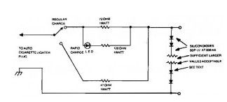
The Car charger for Nicd Battery Packs circuit is very suitable for portable charger, with a few components, allows you to build them in a small case.
The number of silicon diodes across the Car charger output is determined by the voltage of the battery pack.Figure each diode at 0.7 volt. For example, a 10.9- volt pack would require 10.9/0.7 = 15.57, or 16 diodes.
(View)
View full Circuit Diagram | Comments | Reading(999)
Nicd Charger Uses LEDs Constant Current
Published:2013/3/21 4:02:00 Author:Ecco | Keyword: Nicd Charger , LEDs , Constant Current
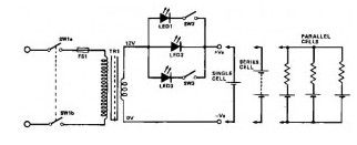
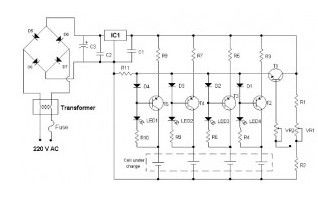
This Nicd charger circuit diagram is another simple NiCd battery charger, and I think its very interesting because uses LEDs to adjust the charging current.
As mentioned above, this Nicd charger circuit uses constant current LEDs to adjust charging current. It makes use of LEDs that pass a constant current of about 15 -mA for an applied voltage range of 2-18 V.They can be paralleled to give any multiple of 15 mA and they light up when current is flowing.
The circuit will charge a single cell at 15, 30 .or 45 mA or cells in series up to the rated supply voltage limit (about 14 V).
(View)
View full Circuit Diagram | Comments | Reading(1232)
Lead Acid Battery Charger with Current Limit
Published:2013/3/20 1:53:00 Author:Ecco | Keyword: Lead Acid, Battery Charger , Current Limit

The Lead Acid battery charger is based at charging voltage 2.4 V per cell, according to many manufacturers recommendations’. Pulse circuit the battery under charge with 14.4 V (6 CEUs x2.4 V per cell) at 120 Hz.
This Lead Acid battery charger design provides current limiting to protect the internal components battery charger circuit while limiting the charging rate to prevent severe damage to discharged lead-acid batteries. The recommended maximum charging time is typically about a quarter of the value of ampere-hour battery. For example, the maximum battery charging current to an average of 44 ampere-hour is 11 A. If the impedance of the load requires a larger charging current of 11 A current limit, the circuit will go into current limit. The amplitude of the charging pulse is controlled to maintain maximum peak charging current of 11 A (8 on average A).
(View)
View full Circuit Diagram | Comments | Reading(2649)
Constant Voltage Current Limited Charger
Published:2013/3/20 1:32:00 Author:Ecco | Keyword: Constant Voltage, Current Limited , Charger
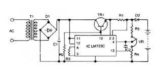
This 12v lead acid battery charger circuit based Regulator IC LM723C. The lead acid battery charger circuit can provide 12 V output voltage at 0.42 A maximum current. This battery charger circuit is design for 12 V Lead Acid battery.
(View)
View full Circuit Diagram | Comments | Reading(1461)
Temperature Controlled NICD Charger
Published:2013/3/10 23:02:00 Author:Ecco | Keyword: Temperature Controlled, NICD Charger
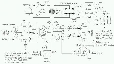
This circuit is for a temperature controlled constant current battery charger. It works with NICD, NIMH, and other rechargeable cells. The circuit works on the principle that most rechargeable batteries show an increase in temperature when the cells becomes fully charged. Overcharging is one of the main causes of short cell life, hot cells pop their internal seals and vent out electrolyte. As cells dry out, they lose capacity. This circuit can quickly charge a rechargeable battery pack without any negative effects. This circuit uses a 22VDC power supply, my version 2 circuit can run from a 12VDC supply such as a solar-powered or automobile power system.
(View)
View full Circuit Diagram | Comments | Reading(1705)
12V Battery charger circuit
Published:2012/9/24 4:13:00 Author:muriel | Keyword: 12V, Battery charger
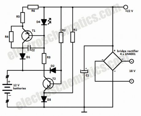
This battery charger circuit can be used to charge one or more batteries with the total nominal voltage of 12 V, meaning ten NiCd battery or six 2 V lead acid. The circuit is pretty small and can be built in a housing network adapter. The incorect usage is impossible: connecting the batteries with reverse polarity, shortcircuit of the output terminals or power loss have no impact on the charger or battery.We can use a transformer with 18 V on the secondary and then using a diode bridge to rectify the 18V ac voltage we get 22V dc on C1.
The completely discharged batteries are charged at the begining with a 6 mA current thru R2-D2 and R4-R6-D1. One the bat. have reached 0.3 – 0.5 V, the base-emitter voltage of T1 is high enough to bring the transistor in conduction.
Green LED D4 is used as an charging indicator and opens T1.There is a 60 mA current flowing thru R5-R6, this means that the charging of a 500 mAh NiCd battery will take 12 hours.
If the battery is connected with reversed polarity or there is a shortcircuit, the power transistor T1 remains blocked and the charging current can not exceed 6 – 12 mA. The current draw at maximum load is around 80 mA.
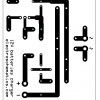
Battery charger circuit schematic
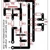
Battery charger PCB Layout
Components ListR1 = R2 = 10KR3 = 1KR4 = 5.6KR5 = R6 = 12Ω
C1 = 1nFC2 = 220µF / 35V
D1 = 1N4001D2 = D3 = 1N4148D4 = green LED
T1 = BD140T2 = BC546?
12 Responses to “12V Battery charger circuit”
(View)
View full Circuit Diagram | Comments | Reading(3024)
Solar Battery Charger Circuits
Published:2012/9/24 4:05:00 Author:muriel | Keyword: Solar, Battery Charger
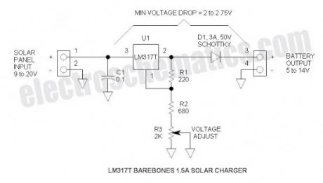
This is the most simple and affordable solar battery charger that the hobbyist can make. It has a few drawbacks over other similar controls, but offers numerous advantages. It is intended for charging lead-acid batteries, but may also be used for charging any battery at a constant voltage. Voltage output is adjustable.Advantages & Disadvantages of this solar charger
+ Simple, small & inexpensive
+ Uses commonly available components
+ Adjustable voltage
+ ZERO battery discharge when sun is not shining
– High drop-out voltage—may be marginal for 6V application
– Current limited to 1.5A
– No LED indicators—no bells or whistles
Solar battery charger specifications
Solar panel rating: 20W (12V) or 10W (6V)
Output voltage range: 5 to 14V (adjustable) (may be reduced further by shorting R2)
Max power dissipation: 10W (includes power dissipation of D1)
Typical dropout voltage: 2 to 2.75V (depending upon load current)
Maximum current: 1.5A (internally limits at about 2.2A)
Voltage regulation: ±100mV (due to regulation of series rectifier)
Battery discharge: 0mA (this control will not discharge the battery when the sun doesn’t shine)
Solar battery charger schematic
6V Applicaton
Output Voltage: Set for 7V
Input voltage:
Battery discharged (6V): 8.75V Min @ 1.5A (this is a little high for panels that are characterized for 6V applications)
Battery charged (7V): 9V Min @ 10mA (e.g.)
12V Application
Output Voltage: Set for 14V
Input voltage:
Battery discharged (12V): 14.75V Min @ 1.5A (Available from solar panel characterized for 12V operation)
Battery charged: (14V): 16V Min
Minimum Head Voltage
This is also referred to “drop-out voltage.” The input voltage must exceed the output voltage by about 2.75V @ 1.5A. Fortunately, when the battery discharged, the output voltage is lower so the solar panel voltage will also be lower.
When fully charged, the battery voltage will be high, but the current is very low—at this point, the drop-out voltage reduces to about 2V and the open circuit solar panel voltage also comes into play. The schottky rectifier was selected to reduce this head voltage requirement—the voltage drop of the schottky is about 0.5V @ 1.5A or about half that of a typical silicon rectifier.
More advanced controls have a much lower head voltage requirement and will function better under marginal conditions.
Maximum Power Dissipation
The power is limited by the thermal resistances of both the LM317T and the heat sink. To keep the junction temperature below the 125°C Max, the power must be limited to about 10W. If a smaller or less effective heat sink is used, the maximum power dissipation must be de-rated. Fortunately, the LM317 has internal temperature limiting so that if it gets too hot, it shuts down thus protecting itself from damage. Max power comes into effect when charging a 12V battery @ 1.5A: e.g. battery voltage = 12V, solar panel = 18V. P = (18V – 12V) * 1.5A = 9W. So thermally, it is carefully matched to the current rating.
If a solar panel that is characterized for 12V is applied with a 6V battery, the maximum current must be reduced to about 0.7A: e.g. battery voltage = 6V, solar panel voltage = 18V. P = (18V – 6V) * 0.7A = 9.6W. In this case, (View)
View full Circuit Diagram | Comments | Reading(3665)
Battery Status Indicator circuit
Published:2012/9/21 3:25:00 Author:Ecco | Keyword: Battery Status, Indicator
If an LED indicator is present in battery powered gadgets such as Emergency lamps, it will consume power even if the gadget is not using. This will reduce the battery voltage since the LED takes around 2 volts. So it is necessary to charge the battery continuously to keep the battery voltage level. This circuit eliminates this and the LEDs turn on only in two conditions. That is in the over charged and over discharged conditions only.
The circuit is basically a voltage controlled switch using Zener diodes. Two state LED indication is provided using a Bicolour LED. Zener diode ZD1 and the PNP transistor T1 forms the over discharge indicator switch. When the battery voltage is above the breakdown point of ZD1 (around 5 volts), it conducts and keeps T1 out of conduction. So the Red half of the bicolur LED remains off. When the battery voltage reduces below 5 volts, Zener turns off allowing T1 to conduct and Red LED turns on. This indicates that the battery is going to the over discharged state.
Zener diode ZD2 and NPN transistor T2 forms the Over charge indicator switch. When the battery voltage is below 6.8 volts (maximum voltage level), ZD cease to conduct and T2 remains off. So that the Green half of the LED also remains off. When the battery voltage increases above 7 volts due to overcharging, ZD2 conducts followed by T2 and Green LED turns on. This is the over charged state. In short, if the battery voltage is between 5 and 7 volts, both LEDs remain off. This reduces the chance of power consumption.
Battery Status Indicator Circuit
Setting
A variable power supply is necessary for the calibration. Provide 5 volts and adjust VR1 till Red LED turns on. At this point, Green LED remains off. Increase the voltage to 7volts and adjust VR2 till Green LED turns on. At this point, Red LED should remain off. Reduce the voltage to 6 volts. Both LEDs should be in the off state.?
21 Responses to “Battery Status Indicator circuit”
source: electroschematics.com
(View)
View full Circuit Diagram | Comments | Reading(2146)
Battery over discharge Indicator
Published:2012/9/21 3:25:00 Author:Ecco | Keyword: Battery , over discharge , Indicator
Most of the battery voltage indicators always remain on even if the load is off. The LED indicator and the circuit consume current which reduces the battery charge and the charger should be continuously switched on to keep the charge of the battery. Here is an ideal solution to prevent this. The indicator turns on only if the load is running. It gives a Red LED indication when the battery voltage reduces below 4.7 volts. So that the load can be switched off to prevent deep discharge of the battery.
The circuit uses the OpAmp CA3140 as a voltage comparator and SCR 2P4M as switch. The inverting input of IC1 gets half supply voltage(3V) from the potential divider R2-R3 and its non inverting input gets a higher voltage through R1. Capacitor C1 maintains stable voltage level at the non inverting input of IC1.Power supply to the IC is obtained through the SCR 2P4M when the load switches on.
Output voltage of IC1 is used to drive the deep discharge indicator LED.As long as the output voltage from IC1 is above 5 volts, Zener conducts and keep the PNP transistor off. So that LED remains off. When the battery voltage reduces below 5 volts, output voltage of IC1 also reduces to 5 volts or less. This makes the Zener out of conduction and T1 turns on and LED lights to indicate low battery level.
Battery over discharge indicator circuit
Setting
Normally IC1 will be off since SCR is not conducting. The gate of SCR (point A) should be connected after the load switch so that SCR fires only when the load turns on. Before connecting the circuit to the battery, adjust the breakdown point of Zener using a variable power supply. Give 5 volts and slowly adjust VR till LED turns on. This is the breakdown point of Zener. It will be around 5 volts. If Zener is still conducting, reduce its value to 4.1 volts. CA3140 is a low power BiMOS Op Amp and its output will be nearly full supply voltage. Once the SCR triggers, it latches itself and remains conducting even if the gate voltage is removed. SCR can be switched off by removing power through S1.?
3 Responses to “Battery over discharge Indicator”
source: electroschematics.com (View)
View full Circuit Diagram | Comments | Reading(1859)
Tricky Charger circuit
Published:2012/9/20 20:53:00 Author:Ecco | Keyword: Tricky Charger
Here is a crude but efficient tricky charger for Lead Acid Battery. It uses a 12 volt car bulb as current regulator and charge status indicator. The brightness of the bulb indicates how much charge is flowing into the battery. When the battery becomes fully charged, lamp turns off. If the lamp is staying on with full brightness for more than 30 minutes, it indicates that the battery is dead and is not accepting charge.Charging current is obtained from a 15-0-15 volt secondary 2 Ampere step down transformer. Diodes D1 and D2 are rectifiers which can handle 3 ampere current. In order to give “Dirty DC” for charging, a low value filtering capacitor C1 is used. So that the DC voltage will have some ripples which is necessary for better charging of lead acid battery.
Tricky Charger Circuit diagram
The trick of the lamp is interesting. A 12 volt car tail lamp bulb is used in the circuit. It is connected in series with the positive output rail so that current flows through the bulb into the positive terminal of the battery. From the positive terminal, current passes through the battery chemistry into the negative terminal and then returns into the transformer. So the current flowing through the bulb depends on how much charge is using by the battery. When the charger is connected to the battery, the lamp turns on only if the battery requires charging current. OFF state of the bulb indicates that the battery is dead. If the battery holds some charge, bulb will turns on. If the battery is partially discharged and holding 50% charge, bulb will light brightly when the charger turns on. Then the brightness gradually reduces and finally the filament appears as a red hot line. This indicates that the battery is fully charged. The bulb also restricts the flow of current like a resistor.?
7 Responses to “Tricky Charger circuit”
Source: electroschematics.com (View)
View full Circuit Diagram | Comments | Reading(1878)
| Pages:2/13 12345678910111213 |
Circuit Categories
power supply circuit
Amplifier Circuit
Basic Circuit
LED and Light Circuit
Sensor Circuit
Signal Processing
Electrical Equipment Circuit
Control Circuit
Remote Control Circuit
A/D-D/A Converter Circuit
Audio Circuit
Measuring and Test Circuit
Communication Circuit
Computer-Related Circuit
555 Circuit
Automotive Circuit
Repairing Circuit