
Battery Charger
Index 9
MAX2003A quick charger practical circuit
Published:2011/6/30 11:11:00 Author:John | Keyword: quick charger
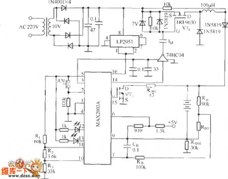
MAX2003A is the NiCad / NiMH battery’s quick charger controller circuit produced by a U.S. company. It can realize automation for the Ni-Cd / Ni-MH battery charging process and ensure the safety, flexibility and reliability of the whole charging process. MAX2003A quick charger practical circuit is shown.
(View)
View full Circuit Diagram | Comments | Reading(1731)
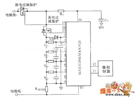
MAX1894/MAX1924 typical application circuit without pre-charging function
Published:2011/6/30 10:44:00 Author:John | Keyword: pre-charging function, typical application
View full Circuit Diagram | Comments | Reading(991)
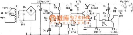
Charger for Motor Vehicle Storage Battery (the 7th)
Published:2011/6/26 9:23:00 Author:Felicity | Keyword: Charger for Motor Vehicle Storage Battery (the 7th)
Work of the circuit
The circuit consists of power circuit, pulse producing circuit and constant current charging circuit. (It is showed in picture 7-152.)
Turn on the power and the 220V AC voltage produces +15V voltage. The voltage is supplied to V and VU through R2 and R5. At the same time, GB begins charging. Change the value of RP2 and RP3 to change the charging current.
If the value of current is larger than the limited value of RP1, the pressure on V4 decreases. So the charging current is limited in a certain range.
Put S1 in the discharging position and S3 in the 50V position. Then turn off S2 and string a load between the poles of GB. At this time, GB is discharging. Put S1 in the charging position and turn on S2. Put S3 in the position of 250V. link the positive pole with the outputting positive pole. link the negative pole with the outputting negative pole. Then connect the 220V AC voltage to make it work. (View)
View full Circuit Diagram | Comments | Reading(1005)
Charger for Motor Vehicle Storage Battery (the 4th)
Published:2011/6/26 9:18:00 Author:Felicity | Keyword: Charger for Motor Vehicle Storage Battery (the 4th)
Work of the circuit
The circuit consists of main charging circuit and controlling circuit. (It is showed in picture 7-149.)
Turn on the power switch S1. 220V AC voltage is reduced by T1. S2 is the transforming switch of the charging output. The ammeter PA has two measuring ranges. One is 0-30A which shows the current of low-capacity battery. While the other one is 0-20A which shows the current of high-capacity battery. The controlling circuit can produce trigger pulse to control the charging current of the charger.
Change the value of RP to change the outputting current of the charger. Make sure that RP’s value is on the top before you start.
(View)
View full Circuit Diagram | Comments | Reading(884)
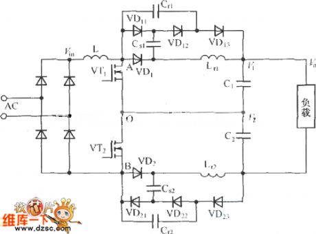
Three-level passive lossless soft-switch PFC topology circuit
Published:2011/6/27 19:38:00 Author:John | Keyword: soft-switch
View full Circuit Diagram | Comments | Reading(1272)
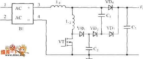
PFC lossless snubber main circuit
Published:2011/6/25 10:58:00 Author:John | Keyword: snubber
The charging process with normal charge mode is generally carried out in the home and public places. The normal charging mode’s charging power level is typically 6.6kW and its typical recharging time is 5 to 8 hours. The power converter of the normal charging mode is similar to that of the emergency charging mode. Normal charging mode also can use a single-stage AC / DC converter. However, with the single-stage PFC converter, the peak current of the switching tube is large. In the two converters, PFC Boost level can use to traditional Boost lifting circuit. The switch can be soft switch or hard switch.
(View)
View full Circuit Diagram | Comments | Reading(1812)
Simple Ni-MH battery charger circuit
Published:2011/6/21 0:12:00 Author:John | Keyword: Ni-MH battery charger
Simple Ni-MH battery charger circuit is shown.
(View)
View full Circuit Diagram | Comments | Reading(2715)
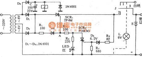
LM393 nickel-cadmium battery charger circuit of high performance-price ratio
Published:2011/6/22 10:15:00 Author:chopper | Keyword: nickel-cadmium battery charger, high performance-price ratio
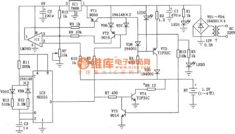
The LM393 nickel-cadmium battery charger circuit of high performance-price ratio is shown as the picture,it has the following features:(1)The process of constant-current charge runs with the process of heavy current discharge.The value of current of constant-current charge is about 300mA.And the discharge current increases along with the increase of battery voltage and the value of discharge current will reach 400mA when the battery is to the full value.The charging time is 1.5 second,discharging time is 0.5 second,and take turns. When the heavy current charge is over,there is about 5mA purling current charging.(2)The detection of battery voltage works during the discharging.It is because that the voltage of charge is greater than the discharge.
(View)
View full Circuit Diagram | Comments | Reading(3726)
MAX1757 lithium ion battery charger circuit
Published:2011/6/17 20:28:00 Author:chopper | Keyword: lithium ion, battery charger
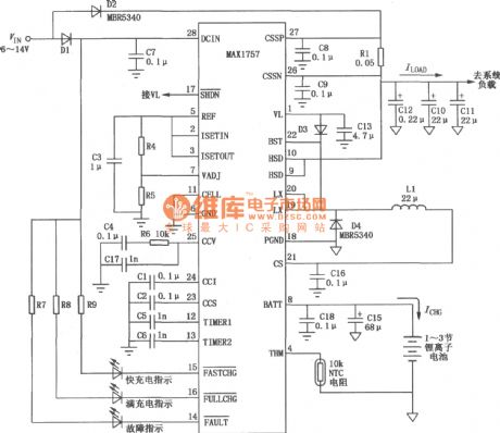
MAX1757 is formed by power supply and charger.As to power supply,there are DC/DC step-down convertor and 5.4V linear voltage regulator.DC/DC convertor can charge the battery with constant current and voltage,and its maximum charge current can reach 1.5A.The typical application circuit of MAX1757 is shown as follows.
(View)
View full Circuit Diagram | Comments | Reading(1971)
current-limiting protection charger of CW117/CW217/CW317 circuit
Published:2011/6/16 0:46:00 Author:chopper | Keyword: current-limiting protection, charger
View full Circuit Diagram | Comments | Reading(1049)
TWH9312 sealed lead-acid battery charger circuit
Published:2011/6/17 6:41:00 Author:chopper | Keyword: sealed, lead-acid battery, charger circuit
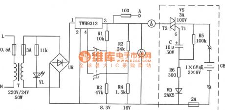
The charger circuit of sealed lead-acid battery is shown as follows.It can charge one or two batteries whose value are 6V or 4Ah for one time. The part of stable voltage adopts switch type stabilized voltage supply module TWH9312,and its scope of input voltage is wide.It also includes protection circuit of over-current,short circuit inside,and it is safe and reliable.
(View)
View full Circuit Diagram | Comments | Reading(3845)
CD4069 solar energy charger circuit
Published:2011/6/17 3:00:00 Author:chopper | Keyword: solar energy, charger circuit
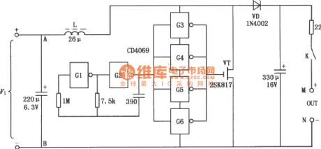
The solar energy charger circuit is as follows.It adopts integrated circuit CD4069(6 gate inverter,and can be replaced by 74HC04),field effect tube VT,diode VD,and some components like resistor and capacitor.The solar energy battery is set up at end A and B,and it is connected to end M,N by chargeable nickel-cadmium battery.
(View)
View full Circuit Diagram | Comments | Reading(2603)
Jinbao BC-60 multiple use charger circuit
Published:2011/6/14 3:19:00 Author:chopper | Keyword: Jinbao, multiple use, charger
View full Circuit Diagram | Comments | Reading(848)
Taiwan clairvoyance charger circuit
Published:2011/6/14 3:20:00 Author:chopper | Keyword: Taiwan, clairvoyance, charger
View full Circuit Diagram | Comments | Reading(996)
Aiwa AC-209H charger circuit
Published:2011/6/14 3:21:00 Author:chopper | Keyword: Aiwa, charger
View full Circuit Diagram | Comments | Reading(1245)
constant current battery charger of CW117/CW217/CW317 circuit
Published:2011/6/16 1:02:00 Author:chopper | Keyword: constant current, battery charger

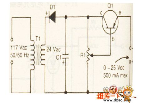
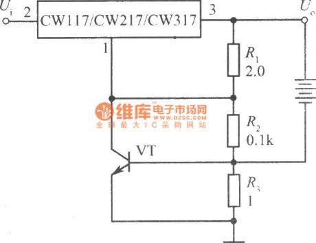
We can produce many kinds of battery charger by using three-terminal adjustable output voltage integrated regulator.The following picture describes a constant current battery charger,This circuit is the same with constant current source.Because the resistance R is 24Ω,the output current Io=1.25/24=52mA,and charge the battery with the constant current 52mA.It can offer different charge current by changing the value of resistance R.
(View)
View full Circuit Diagram | Comments | Reading(941)
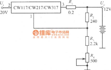
12V constant voltage charger of CW117/CW217/CW317 circuit
Published:2011/6/16 0:45:00 Author:chopper | Keyword: 12V, constant voltage, charger
View full Circuit Diagram | Comments | Reading(894)
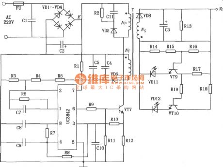
UC3842 battery charger of lectromotive bicycle circuit
Published:2011/6/22 9:54:00 Author:chopper | Keyword: battery charger, lectromotive bicycle
View full Circuit Diagram | Comments | Reading(9780)
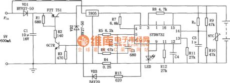
STD9732 simple charger circuit
Published:2011/6/17 20:39:00 Author:chopper | Keyword: simple, charger circuit
View full Circuit Diagram | Comments | Reading(999)
CD060 nickel-cadmium battery charger circuit of timing function
Published:2011/6/17 6:51:00 Author:chopper | Keyword: nickel-cadmium battery, charger circuit, timing
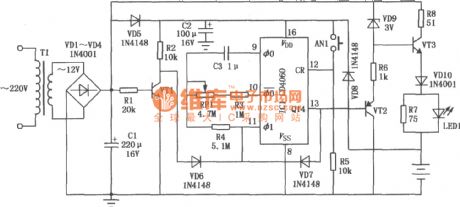
This circuit is a timing charger,the charging time can be adjusted between 5h and 25h.If the power supply is cut during charging,this circuit can accumulate the total time.This circuit can charge the number 5 nickel cadmium battery. (View)
View full Circuit Diagram | Comments | Reading(1273)
| Pages:9/13 12345678910111213 |
Circuit Categories
power supply circuit
Amplifier Circuit
Basic Circuit
LED and Light Circuit
Sensor Circuit
Signal Processing
Electrical Equipment Circuit
Control Circuit
Remote Control Circuit
A/D-D/A Converter Circuit
Audio Circuit
Measuring and Test Circuit
Communication Circuit
Computer-Related Circuit
555 Circuit
Automotive Circuit
Repairing Circuit