
Battery Charger
Index 7
Automatic charger circuit diagram
Published:2011/7/25 0:11:00 Author:Sophia | Keyword: Automatic charger
Circuit theory
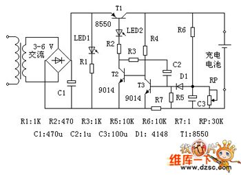
The circuit is designed aiming at a single-cell Ni-MH battery. Figure: electricity is transformed through the transformer and rectified by full-bridge. Capacitor C1 is filtered into DC. LED1 is the power indicator, LED2 is the charge indicator. T1 is the charge control transistor, which works in the switch state; T2, T3 and C2 constitute a monostable flip-flop. R6 and RP constitute a limited pressure sampling circuit. R7 is limiting the sampling resistor.
Standby: the power must be on, if not, transistor T2 will be cut-off because of no base voltage, and transistor T1 is also closed, no voltage is outputed. At this moment, only the power indicator LED1 lights.
(View)
View full Circuit Diagram | Comments | Reading(1570)
96_V_AT_20_mA
Published:2009/6/28 23:53:00 Author:May
Developed to charge 200-mAh nickel-cadmium batteries for two transceivers simultaneously. Batteries will be fully charged in 14 hours, using correct 20-mA charging rate. Zone diode ensures that voltage cannot exceed safe value if battery is accidentally disconnected while under charge. Diode types are not critical.-D. A. Tong,A Pocket V.H.F. Transceiver, Wireless World, Aug, 1974 p 293-298. (View)
View full Circuit Diagram | Comments | Reading(817)
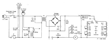
BATTERY_CHARGING_REGULATOR
Published:2009/6/24 22:20:00 Author:May
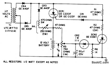
The circuit is capable of charging a 12 volt battery at up to a six ampere rate. Other volt-ages andcurrents, from6 to600volts and upto 300 amperes, can be accommodated by suitable component selection. When the battery voltage reaches its fully charged level, the charging SCR shuts off, and a trickle charge as deter-mined by the value of R4 continues to flow. (View)
View full Circuit Diagram | Comments | Reading(2159)
SIMPLE_NI_CAD_BATTERY_ZAPPER
Published:2009/6/24 22:19:00 Author:May
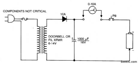
This circuit is used to clear internal shorts in nickel cadmium batteries. To operate, connect ni-cad to output and press the pushbutton for three seconds. (View)
View full Circuit Diagram | Comments | Reading(869)
200_mA_HOUR,12_V_NI_CAD_BATTERY_CHARGER
Published:2009/6/24 22:13:00 Author:May
This circuit charges the battery at 75 mA until the battery is charged, then it reduces the current to a trickle rate. It will completely recharge a dead battery in four hours and the battery can be left in the charger indefinitely. To set the shut-off point, connect a 270-ohm, 2-watt resistor across the charge terminals and adjust the pot for 15.5 volts across the resistor. (View)
View full Circuit Diagram | Comments | Reading(1331)
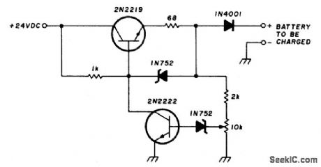
AUTOMATIC_SHUTOFF_BATTERY_CHARGER
Published:2009/6/24 22:11:00 Author:May
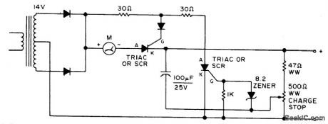
Adjust by setting the 500 ohm resistor while attached to a fully charged battery. (View)
View full Circuit Diagram | Comments | Reading(1357)
BATTERY_CHARGER
Published:2009/6/24 22:11:00 Author:May
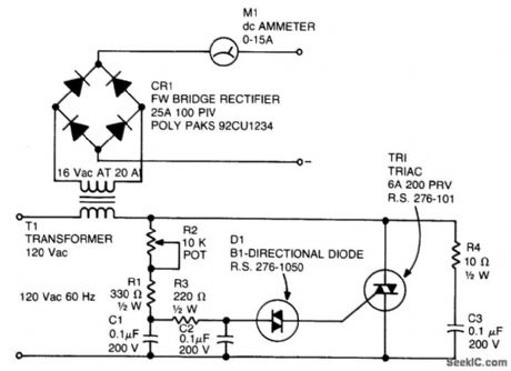
A diac is used in the gate circuit to provide a threshold level for firing the triac. C3 and R4 provide a transient suppression network. RI, R2, R3, C1, and C2 provide a phase-shift network for the signal being applied to the gate. R1 is selected to limit the maximum charging cur-rent at full rotation of R2. (View)
View full Circuit Diagram | Comments | Reading(0)
BATTERY_CONDITION_INDICATOR_FOR_12_V_BATTERIES
Published:2009/6/22 22:30:00 Author:May
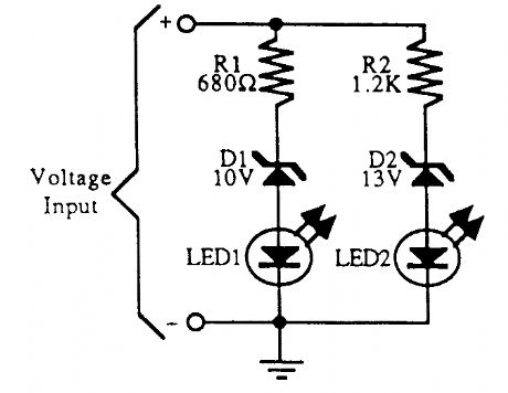
A simple battery condition indicator. Choose the Zener diodes to provide a window for over/un-der voltage indication. (View)
View full Circuit Diagram | Comments | Reading(1921)
LITHIUM_MEMORY_BACKUP_BATTERY_REPLACEMENT
Published:2009/6/22 22:30:00 Author:May
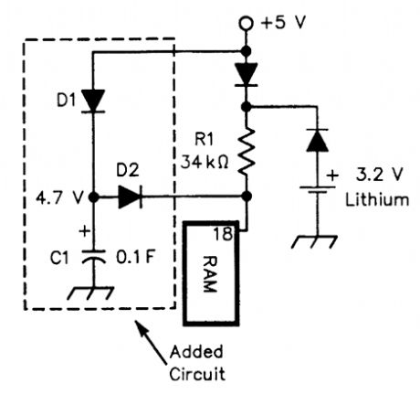
Physically very small high-capacitance capacitors are available for memory backup. Here, a 0.1-F (100,000μF) capacitor and two diodes replace the lithium battery. The lithium battery can be re-tained as well, providing double backup. (View)
View full Circuit Diagram | Comments | Reading(1287)
BATTERY_STATUS_INDICATOR
Published:2009/6/22 22:29:00 Author:May
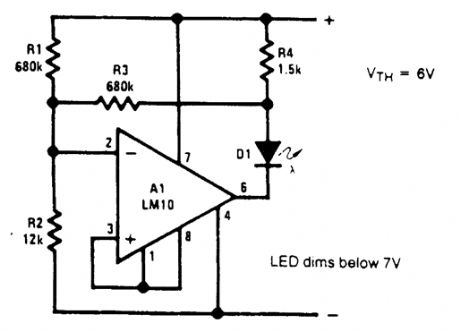
In battery-powered circuitry, there are some advantages to having an indicator to show when the battery voltage is high enough for proper circuit operation. This is especially true for instruments that can produce erroneous data.The battery status indicator is designed for a 9-V source. It begins dimming noticeably below7V artd it extinguishes at 6 V. If the warning of incipient battery failure is not desired, R3 can be re-rnoved and the value ofJR, is halved. (View)
View full Circuit Diagram | Comments | Reading(3)
LOW_BATTERY_CIRCUIT
Published:2009/6/22 22:25:00 Author:May
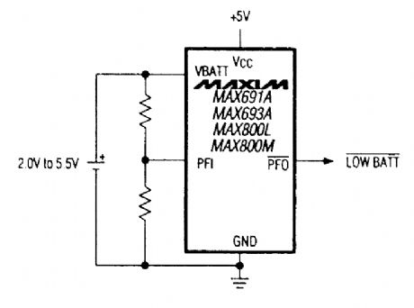
A Maxim MAX691A series IC allows low-battery detection. (View)
View full Circuit Diagram | Comments | Reading(1027)
BATTERY_CHARGER_PROBE
Published:2009/6/22 22:25:00 Author:May
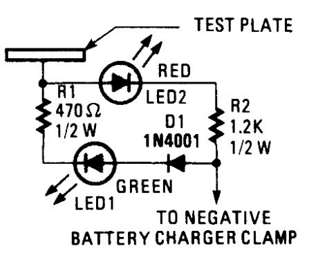
This battery-charger probe can keep you from damaging batteries or yourself by testing to see if the charger is already on and/or connected improperly.To use the probe, the positive cable clamp is first connected to the positive battery terminal. Then, the test plate is touched to the negative terminal of the battery. If the battery is connected properly, current will pass from the test plate through RI, LED1, Dl, the negative charger, and into the positive side of the batteries. If LED1 (the green LED) lights, you can clamp on the negative lead and turn on the charger.If the terminals are reversed, current will flow in the opposite direction, causing LED2 to light, warning you of danger. When the cable is reversed, Dl protects LED1 from excessive reverse volt-age. If that happens, immediately turn the power off, and right the cable connections. Finally, if the battery charger is on, both LEDs will light because chargers actually produce pulsating dc and rely on the battery to act as a filter. (View)
View full Circuit Diagram | Comments | Reading(934)
BATTERY_BUTLER
Published:2009/6/22 22:17:00 Author:May
The battery butler solves the common problems associated with the maintenance and operationof NiCad batteries The battery butler,by initially discharging a NiCad battery to a preset point,reduces the possibility of the“memory”effect occurring,Once discharged,a battery is then usuallycharged at 25%and reduce the internal cell pressure increase by 40% or more Once the battery ISfully charged,a trickle charge IS provided to maintain the battery In a fully charged state The battery butler circuit can be bypassed,and the existing fast-charger used,if needed (View)
View full Circuit Diagram | Comments | Reading(1765)
NICAD_BATTERY_CHARGER_1
Published:2009/6/19 3:13:00 Author:May
This circuit has a current regulator and uses an external timer to control the charging rate. (View)
View full Circuit Diagram | Comments | Reading(1238)
BATTERY_SAVER_CIRCUIT
Published:2009/6/17 1:48:00 Author:May
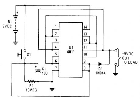
This battery saver circuit can automatically turn off a small piece of test equipment after a desired period of time, allowing you to leave your shop worry free.This circuit uses a CD4011 IC to act as a simple timer. One section acts as an RC discharge timer (pin 7). This causes its output to go low, holding the three other outputs high acting as a 9-V source.After C1/R1 discharges approximately 10 minutes, the output drops to zero. S1 resets the circuit. (View)
View full Circuit Diagram | Comments | Reading(3235)
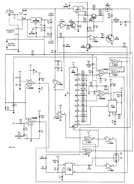
INTELLIGENT_BATTERY_CHARGING_CIRCUIT
Published:2009/6/16 3:35:00 Author:May
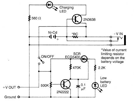
Intended for a Nicad application this charging circuit can be used with a wide range of batteries. A low-battery detector is intended. The trip voltage is set via the 500-kΩ pot. Select R, for the battery you intend to use. (View)
View full Circuit Diagram | Comments | Reading(1227)
SOLAR_POWERED_BATERY_CHARGER
Published:2009/6/16 3:30:00 Author:May
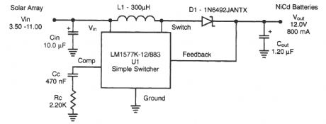
A National Semiconductor LM1577 IC is used in a step-up regulator to charge Nicad batteries from a solar panel. (View)
View full Circuit Diagram | Comments | Reading(2214)
BATTER_CHARGER
Published:2009/6/16 3:13:00 Author:May
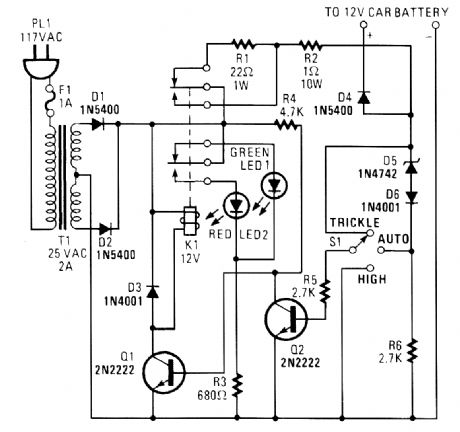
The circuit is capable of supplying either a trickle (50 mA) or high-current (1-A) charge. You can select either charging dtethod or an automatic mode that will first trickle charge a battery if it is particularly low before switching to high-current charging.If the battery's voltage is low, Zener-diode D5 will not conduct sufficient current to produce a voltage drop across R6 to turn Q2 on. With Q2 off, R4 pulls the base of Q1 high, turning it on. That activates K1. With K1 active, the only thing between the battery and the power supply is R2 and D4 (which prevents current from flowing through the circuit from the battery).Once the battery charges a bit, the current through D5 increases, causing a voltage drop across R6 that is of sufficient magnitude to turn on Q2. Transistor Q2, in turn, grounds the base of Q1, keeping it off. With Q1 off, K1 remains in its normally closed state. That places R1 in series with the battery, thereby reducing the current to a trickle. (View)
View full Circuit Diagram | Comments | Reading(1933)
RF_TYPE_BATTERY_CJARGER
Published:2009/6/16 3:08:00 Author:May
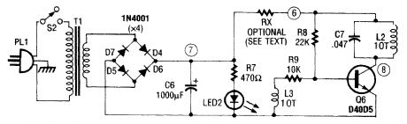
This type of charger couples RF from L2 to an external pickup coil The pickup coil connects to a rectifier and batteryto be charged This idea is handy because no wire or contacts are required L2 is 10T #24 wire and L3 is 10T #30 wire. Both cois are mounted on a 1''×1/4'' ferrite rod. (View)
View full Circuit Diagram | Comments | Reading(1156)
500 MA USB compatible Nimh battery charge control circuit--CN3058
Published:2011/7/12 5:12:00 Author:chopper | Keyword: 500 MA, USB compatible, Nimh battery, charge control, Section 1-4, high efficiency
Overview :CN3058 is a charger circuit which can charge rechargeable batteries like single lithium iron phosphate in constant current/voltage mode.The device includes power transistor,and its application does not require the external current detective resistor and blocking diode.CN3058 only requires few external components,and works under USB bus technology specifications,thus it is ideal for portable applications.Heat modulation circuit can control the chip temperature within safety range if the power consumption of devices is bigger or the environmental temperature is higher. (View)
View full Circuit Diagram | Comments | Reading(1164)
| Pages:7/13 12345678910111213 |
Circuit Categories
power supply circuit
Amplifier Circuit
Basic Circuit
LED and Light Circuit
Sensor Circuit
Signal Processing
Electrical Equipment Circuit
Control Circuit
Remote Control Circuit
A/D-D/A Converter Circuit
Audio Circuit
Measuring and Test Circuit
Communication Circuit
Computer-Related Circuit
555 Circuit
Automotive Circuit
Repairing Circuit