
Battery Charger
Index 6
CHARGER_EXTENDS_LEAD_ACID_BATTERY_LIFE
Published:2009/7/9 20:32:00 Author:May
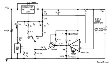
The circuit furnishes an initial charging voltage of 2.5 V per cell at 25'C to rapidly charge a battery. The charging current decrbases as the battery charges, and when the current drops to 180 mA, the charging circuit reduces the output voltage to 2.35 V per cell, floating the battery in a fully charged state. This lower voltage prevents the battery from overcharging, which would shorten its life. The LM301A compares the voltage drop across R1 with an 18-mV reference set by R2. The comparator's output controls the voltage regulator, forcing it to produce the lower float voltage when the battery-charging current pass-ing through RI drops below 180 mA. the 150-mV difference between the charge and float voltages is set by the ratio of R3 to R4. The LEDs show the state of the circuit. (View)
View full Circuit Diagram | Comments | Reading(1509)
+12_Vdc_MOBILE_BATTERY_CHARGER
Published:2009/7/9 20:28:00 Author:May
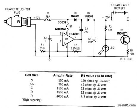
This circuit provides up to 20 V output from a 12-V automotive supply, to enable constant current charging of Nicad battery assemblies up to about 18 V total. V1 forms a square-wave oscillator, D1 and D2, coupling this square wave to the 12-V battery supply to obtain over 20 Vdc. If this is not needed, S1 is left open. Q1 forms a current regulator to determine the charging rate of the rechargeable battery. R4 is selected from the table or it can be switched with a rotary selector switch. (View)
View full Circuit Diagram | Comments | Reading(2441)
12_V_BATTERY_CHARGER
Published:2009/7/9 5:44:00 Author:May

This simple charger uses an LM350 regulator as a battery charger. (View)
View full Circuit Diagram | Comments | Reading(0)
BATTERY_CHARGER
Published:2009/7/9 5:42:00 Author:May
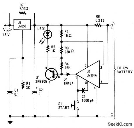
This high-performance charger quickly charges gelled lead-acid batteries, and turns off at full charge. At first, the charge current is held at 2 A, but as battery voltage rises, current decreases. When current falls to 150 mA, the charger automat- ically switches to a lower float voltage to keep from overcharging. When you hit full charge, transistor Q1 lights the LED to indicate that status. (View)
View full Circuit Diagram | Comments | Reading(0)
Circuit of Auto power off Nickel-cadmium Battery Charger
Published:2011/8/2 Author:Zoey | Keyword: Auto power off, Nickel-cadmium Battery, Charger
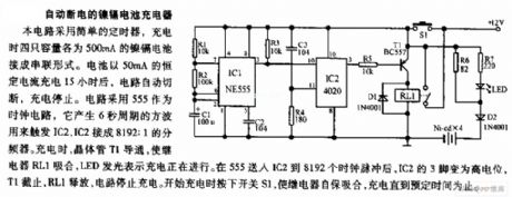
This circuit uses a simple timer. The four 500-mA Nickel-cadmium cells are connected in series. After charging for 15 hours in a constant current of 50mA, the circuit will cut off automatically, the charging process will be ceased. This circuit uses a 555 timer as a clock circuit, and it can produce the square wave in a period of 6s and use the wave to trigger IC2. IC2 will be connectedto be a divider of 8192:1. While charging, transistor T1 will conduct, forcing the relay RL1 to pick up. Light of LED indicates the formal process of charge. After the 555 be sent to IC2 and 8192 clock time pulses, pin 3 of IC2 will be in high level, T1 will stop working, RL1 will release, the circuit will stop charging. Pressing the switch S1, the relay will pick up automatically, and charging process will proceed until the scheduled time. (View)
View full Circuit Diagram | Comments | Reading(1929)
Auto Parallel Charger Circuit
Published:2011/8/1 6:14:00 Author:Zoey | Keyword: Auto Parallel, Charger Circuit
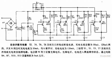
T2, T4, T6, T8 and the relevant accessories constitute a constant circuit, the charge current is 50mA and 120mA.As soon as swtich K is closed, the charge current will turn to be 50mA; and if K is disconnected, the charge current will turn to be 120mA. Triode T1, T3, T5 and T7 and the rellevant accessories constitute a detection citcuit that is in a charge state. Potentiometer W is used to set to charge voltage. When it is fully charged, the battery will turn into a trickle maintain state. Trickle is set about 9mA by the resistances R4, R7,R10 and R13. (View)
View full Circuit Diagram | Comments | Reading(1161)
Full_wave_trigger_circuit_for_a_900_watt_load_using_a_triac_and_UJT
Published:2009/7/21 8:10:00 Author:Jessie
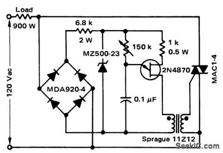
Full-wave trigger circuit for a 900-watt load using a triac and UJT (courtesy Motorola Semiconductor Products Inc.). (View)
View full Circuit Diagram | Comments | Reading(1240)
14_VOLT,4_AMP_BATTERY_CHARGER_POWER_SUPPLY
Published:2009/7/3 4:18:00 Author:May
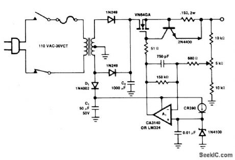
Operation amplifier A1 directly drives the VN64GA with the error signal to control the output voltage. Peak rectifier D1, C1 supplies error amplifier A1 and the reference zener. This extra drive voltage must exceed its source voltage by several volts for the VN64GA to pass full load current. The output voltage is pulsating dc which is quite satisfactory for battery charging. To convert the system to a regulated dc supply, capacitor C2 is increased and another electrolytic capacitor is added across the load. The response time is very fast, being determined by the op-amp. The 2N4400 current limiter circuit prevents the output current from exceeding 4.5 A. However, maintaining a shorted condition for more than a second will cause the VN64GA to exceed its temperature ratings.A generous heat sink, on the order of 1℃/W, must be used. (View)
View full Circuit Diagram | Comments | Reading(1636)
VERSATILE_BATTERY_CHARGER
Published:2009/7/3 4:15:00 Author:May
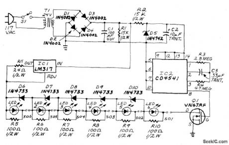
An LM317 voltage regulator is configured as a constant-current source. It is used to supply the 50 mA charging current to S01-S06, an array of AA-cell battery holders. Each of the battery holders is wired in series with an LED and its associated shunt resistor. When the battery holder contains a battery, the LED glows during charging. Each battery holder/LED combination is paralleled by a 5.1-volt Zener diode. If the battery holder is empty, the Zener conducts the current around the holder.A timing circuit prevents overcharging. When power is applied to the circuit, timing is initiated by IC2, a CD4541 oscillator/programmable timer. The output of IC2 is fed to Q1. When that output is high, the transistor is on, and the charging circuit is completed.When the output is low, the transistor is off, and the path to ground is interrupted. (View)
View full Circuit Diagram | Comments | Reading(2713)
BATTERY_CHARGER_OPERATES_ON_SINGLE_SOLAR_CELL
Published:2009/7/3 4:11:00 Author:May
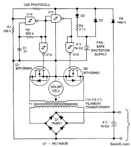
The circuit charges a 9-V battery at about 30 mA per input ampere at 0.4 V. U1, a quad Schmitt trigger, operate as an astable multivibrator to drive push-pull TMOS devices Q1 and Q2. Power for U1 is derived from the 9-V battery via D4; power for Q1 and Q2 is supplied by the solar cell. The multivibrator frequency, determined by R2-C1, is set to 180 Hz for maximum efficiency from a 6.3-V filament transformer, T1. The secondary of the transformer is applied to a full wave bridge rectifier, D1, which is connected to the batteries being charged. The small Ni-Cad battery is a fail-safe excitation supply to allow the system to recover if the 9-V battery becomes fully discharged.A CdS photocell shuts off the oscillator in darkness to preserve the fail-safe battery during shipping and storage, or prolonged darkness (View)
View full Circuit Diagram | Comments | Reading(1174)
WIND_POWERED_BATTERY_CHARGER
Published:2009/7/3 4:06:00 Author:May

The dc motor is used as a generator with the voltage output being proportional to its rpm. The LTC1042 monitors the voltage output and provides the following control functions.
1. If generator voltage output is below 13.8 V, the control circuit is active and the Ni-Cad battery is charging through the LM334 current source. The lead acid battery is not being chirged.2. If the generator voltage output is between 13.8 V and 15.1 V, the 12 V lead acid battery is being charged at about 1 amp/hour rate (limited by the power FET).3. If generator voltage exceeds 15.1 V (a condition caused by excessive wind speed or 12 V battery being fully charged) then a fixed load is connected limiting the generatorrpm to prevent damage.
This charger can be used as a remote source of power where wind energy is plentiful such as on sailboats or remote radio repeater sites. Unlike solar powered panels, this system will function in bad weather and at night. (View)
View full Circuit Diagram | Comments | Reading(4113)
WARNING_LIGHT_OPERATES_FROM_BATTERY_POWER_SUPPLY
Published:2009/6/30 23:50:00 Author:May
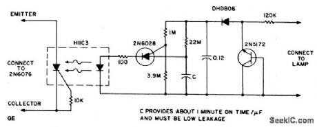
The circuit provides illumination when darkness comes. By using the gain available in darlington transistors, this circuit is simplified to use just a photodarlington sensor, a darlington amplifier, and three resistors. The illumination level will be slightly lower than normal, and longer bulb life can be expected, since the D40K saturation voltage lowers the lamp operating voltage slightly. (View)
View full Circuit Diagram | Comments | Reading(1023)
GELLED_ELECTROLYTE_BATTERIES
Published:2009/6/29 23:05:00 Author:May
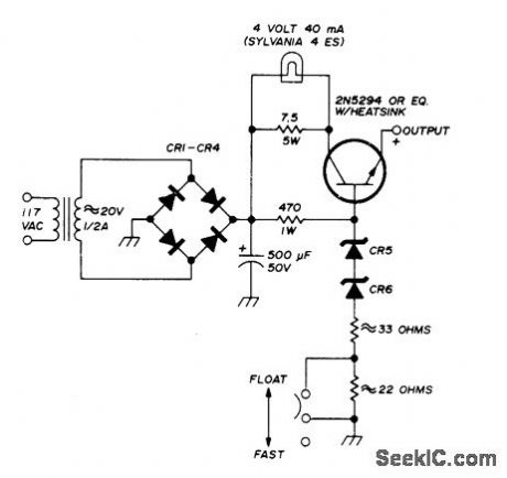
Constant-voltage charger for Globe-Union 12-V gelled-electrolyte storage batteries can provide either fast or float charging. Constant voltage is maintained by series power transistor and series-connected zeners. Output voltage is 13.8 V for float charging and 14.4 V for fast charging.-E. Noll, Storage-Battery QRP Power, Ham Radio, Oct. 1974, p 56-61. (View)
View full Circuit Diagram | Comments | Reading(2387)
SOLAR_POWER_OVERCHARGE_PROTECTION
Published:2009/6/29 22:02:00 Author:May
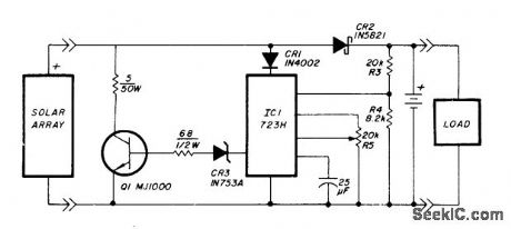
Voltage regulator is connected across solar-cell away as shown to prevent damage to storage battery by overcharging. Series diode prevents array from discharging battery during hours of darkness. Regulator does not draw power from battery, except for very low current used for voltage sampling. Battery can be lead-calcium, gelled-electrolyte, or telephone-type wet cells, For repeater application described, two Globe Union GC12200 40-Ah gelled-electrolyte batteries were used to provide transmit current of 1.07 A and idle current of 12 mA.-T. Handel and P. Beauchamp, Solar-Powered Repeater Design, Ham Radio, Dec. 1978, p 28-33. (View)
View full Circuit Diagram | Comments | Reading(3040)
NICAD_CHARGER_FOR_AUTO
Published:2009/6/29 21:35:00 Author:May
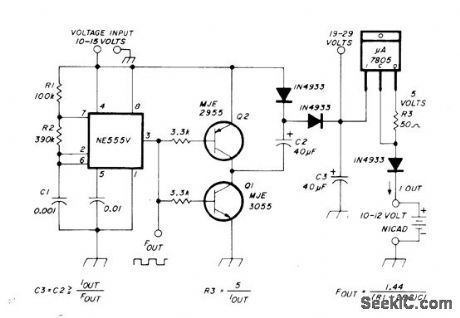
Voltage doubler provides at least 20 V from 12-V auto battery, for constant-current charging of 12-V nicads, using NE555 timer and two power transistors. Doubled voltage drives source current into three-terminal current regulator. Switching frequency of NE555 as MVBR is 1.4 kHz. Charging currentis set at 50 mA for charging ten 500-mAh nicads.-G. Hinkle, Constant-Current Battery Charger for Portable Operation, Ham Radio, April 1978, p 34-36. (View)
View full Circuit Diagram | Comments | Reading(2054)
NICAD_ZAPPER
Published:2009/6/29 21:33:00 Author:May
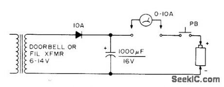
Simple circuit often restores dead or defective nicad battery by applying DC overvoltage at current up to 10 A for about 3 s. Longer treatment may overheat battery and make it explode.-Circuits, 73 Magazine, July 1977,p 35. (View)
View full Circuit Diagram | Comments | Reading(1239)
LED_TRICKLE_CHARGER
Published:2009/6/29 21:32:00 Author:May
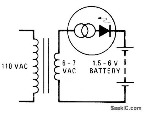
Constant-current characteristic of National NSL4944 LED is used to advantage in simple half-wave charger for batteries up to 6 V.- Linear Applications, Vol.2, National Semiconductor, Santa Clara, CA, 1976,AN-153,p 2. (View)
View full Circuit Diagram | Comments | Reading(954)
NICAD_CHARGER
Published:2009/6/29 21:21:00 Author:May
Switch gives choice of two constant-current charge rates. With 10 ohmsfor R1, rate is 60 mA, while 200 ohms for R2 gives 3 mA. Silicon diodes CR1 and CR2 have combined voltage drop of 1.2 V and emitter-base junction of Q1 has 0.6-V drop, for net drop of 0.6 V across R1 or R2. Dividing 0.6 by desired charge rate in amperes gives resistance value.-M. Alterman, A Constant-Current Charger for Nicad Batteries, QST, March 1977, p 49. (View)
View full Circuit Diagram | Comments | Reading(1067)
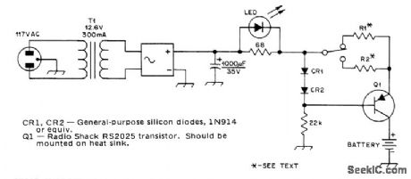
LED_VOLTAGE_INDICATOR
Published:2009/6/29 21:13:00 Author:May
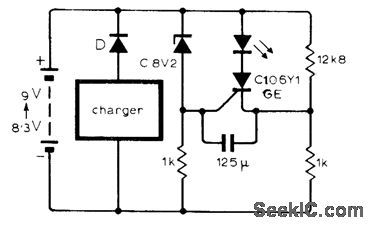
Circuit shown uses LED to indicate, by lighting up, that battery has been charged to desired level of 9 V. Circuit can be modified for other charging voltages. Silicon switching transistor can be used in place of more costlythyristor.-P. R. Chetty, Low Bat-tery Voltage Indication, Wireless World, April 1975, p 175. (View)
View full Circuit Diagram | Comments | Reading(1021)
12_V_AT_8_A
Published:2009/6/29 21:08:00 Author:May
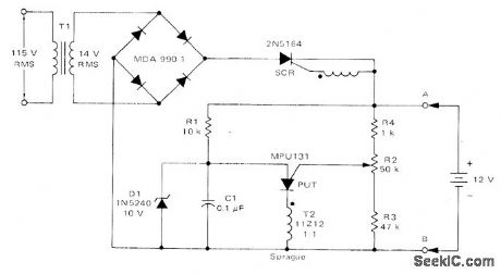
Charging circuit for lead-acid storage batteries is not damaged by short-circuits or by connecting with wrong battery polarity. Battery provides currentfor charging C1 in PUT relaxation oscillator. When PUT is fired by C1, SCR is turned on and applies charging current to battery. Battery voltage increases slightly during charge, increasing peak point voltage of PUT and making C1 charge to slightly higher voltage. When C1 vo!tage reaches that of zener D1, oscillator stops and charging ceases. R2 sets 12 V maximum battery voltage between 10 and 14 V during charge.-R. J. Haver and B. C. Shiner, Theory, Characteristics and Applications of the Programmable Unijunction Transistor, Moto-rola, Phoenix, AZ, 1974,AN-527, p 10. (View)
View full Circuit Diagram | Comments | Reading(2832)
| Pages:6/13 12345678910111213 |
Circuit Categories
power supply circuit
Amplifier Circuit
Basic Circuit
LED and Light Circuit
Sensor Circuit
Signal Processing
Electrical Equipment Circuit
Control Circuit
Remote Control Circuit
A/D-D/A Converter Circuit
Audio Circuit
Measuring and Test Circuit
Communication Circuit
Computer-Related Circuit
555 Circuit
Automotive Circuit
Repairing Circuit