
Battery Charger
Index 11
Practical constant current charger circuit
Published:2011/5/24 3:26:00 Author:John | Keyword: constant current charger
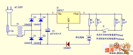
This circuit is actually a constant current source. Nuclear device is an integrated three-terminal adjustable regulator LM317T. Within the sufficient power supply voltage, LM317T can maintain a 1. 25V higher voltage of the + Vout than that of the ADJ. See the connection in the figure. The terminal end of ADJ is connected directly to rechargeable batteries. However, the internal resistance for ADJ terminal end is large (the current does not exceed 50μA under normal circumstances), so the circuit can be approximately regarded as an open circuit. But it can sample out of the voltage. If LM317T improves the voltage on the + Vout terminal end to be higher than that of ADJ terminal end of about 1.25V, the resistor cross-connected to the + Vout and ADJ can have the current of 1.25V/25.5Ω = 0. 05A = 50mA. (25.5Ω is the total resistance for the situation when R1 and R2 are parallel placed with the opening switch). Such current flows through the battery to charge the battery within a constant current.
(View)
View full Circuit Diagram | Comments | Reading(2626)
electric bicycle quick charger circuit
Published:2011/5/25 20:08:00 Author:John | Keyword: electric bicycle, quick charger
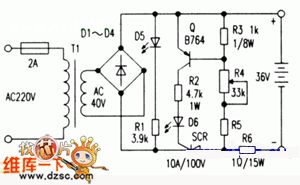
The AC220V electricity is stepped-down through transformer T1 and is regulated through the full-wave rectifier D1-D4. Thus the charging circuit is supplied to work. Then the output end is correctly accessed to the set recharged bottle. If each half-wave peak value of the rectifier output ripple voltage is higher than the output voltage of the battery, the thyristor SCR is triggered to conduct by the Q collector current. The current charges the battery through the SCR. When the pulsating voltage is close to battery voltage, the SCR is off and charging process stops. Conduction voltage for transistor Q can be adjusted by the regulation of R4. The R4 is generally adjusted, from large value to small value, to trigger SCR. LED D5 in the figure is used for the power indicator and D6 is used for charging instructions. (View)
View full Circuit Diagram | Comments | Reading(2138)
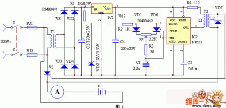
back-up power supply automatic charger circuit
Published:2011/5/25 20:06:00 Author:John | Keyword: automatic charger
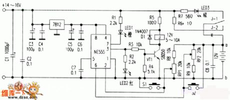
Backup power supply is temporary power supply equipment which is set in case of power failure or other reasons. Common ones are small back-up power generators and a variety of batteries. Among them, an economic and durable lead-acid storage battery is the first choice for back-up power supply. The authors have considered carefully designing an automatic battery charger for lead-acid batteries. The circuit is as shown in the figure (emitting the part that electricity is being bucked and rectified)
The core part of the circuit is composed by NE555 hysteresis comparator . R8, R9, RP1 and RP2 constitute sampling circuit and LED1-LED3 is an indicator for charging status. The charger of the battery is connected with an electrical relay, leading the cutting-off to be more reliable. S1 and S2 are touch switched, which are used to manually control the charging process. As a result, the circuit becomes more flexible and more convenient. (View)
View full Circuit Diagram | Comments | Reading(3003)
Pulse current limiting battery charger circuit
Published:2011/6/4 12:10:00 Author:John | Keyword: battery charger
Pulse current limiting battery charger circuit is shown below.
(View)
View full Circuit Diagram | Comments | Reading(6500)
Yilaida electric bicycle battery charger circuit
Published:2011/6/4 11:36:00 Author:John | Keyword: electric bicycle, battery charger
Yilaida electric bicycle battery charger circuit is shown below.
(View)
View full Circuit Diagram | Comments | Reading(7086)
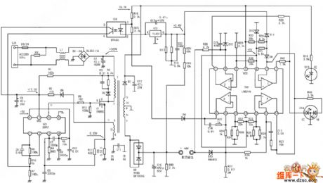
power supply cavity monitoring circuit
Published:2011/6/4 11:29:00 Author:John | Keyword: power supply, cavity
Low level electricity logic circuit partially goes through the optical coupling, so that the power supply is isolated. When the power supply fails, the output level electricity is down to the logic level. Adjust the output of trigger to turn off the circuit.
The response time of the circuit is 2m8. When AC voltage is normally over zero, there is no effect on the circuit. Power consumption of the circuit is 50mW.
(View)
View full Circuit Diagram | Comments | Reading(932)
automobile battery charger circuit
Published:2011/6/3 20:10:00 Author:chopper | Keyword: automobile, battery charger
There is a automobile battery charger of adjustable type.The charging voltage between 6V and 50V is adjustable,and the maximum charge current can reach 20A.It applies to automobile battery charger of different type,such as 12V,24V,36V and so on.
(View)
View full Circuit Diagram | Comments | Reading(5548)
Automatic charger circuit
Published:2011/6/3 20:04:00 Author:chopper | Keyword: Automatic charger
View full Circuit Diagram | Comments | Reading(1077)
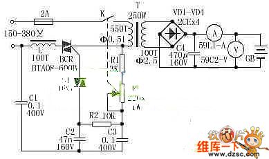
Portable SCR charger circuit
Published:2011/5/24 2:43:00 Author:John | Keyword: Portable SCR charger
Charger directly uses 220V AC power supply. It achieves the output voltage adjustment starting from 0V by controlling the triggering circuit. It is suitable for charging 12V-220V battery (s).
The main control circuit is composed by the fuse FU, ammeter and SCR VS. When the battery, as well as the batteries, requiring being charged is connected, the SCR VS gains trigger pulse. Conduction angle of VS is regulated by pulses with different width. And the RP can be adjusted to meet the charge of different battery or batteries within different charging current or voltage. (View)
View full Circuit Diagram | Comments | Reading(5203)
Maintenance-free sealed micro-battery circuit
Published:2011/5/24 3:02:00 Author:John | Keyword: micro-battery
Micro-battery described in this article has the following characteristics: (1) There is no liquid flow inside, so that it can be placed in any direction without influencing the function. (2) There is no need for acid-supply and other maintenance work during the entire applying process. The battery surface is clean and not damp. (3) Gases produced by the charging process can be absorbed by a special anode. The overall sealed performance can be achieved. So it is not necessary to worry about the corrosion and pollution to electrical equipment.(4) Its charge and discharge cycles can be over more than 300 times within proper use. And the service life is up to 3 years. (5) It has very low ability to internal self-discharge. Its rate for self-discharging is less than 1%. (View)
View full Circuit Diagram | Comments | Reading(1231)
Rechargeable battery technology and charging method circuit
Published:2011/5/24 1:48:00 Author:John | Keyword: Rechargeable battery
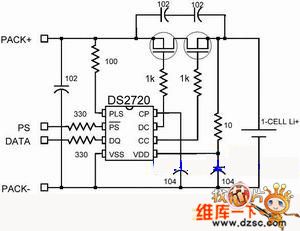
Battery applications have never been so extensive. Batteries are becoming smaller and lighter. And they can accommodate more energy in every unit volume. The main driving force of the battery is mainly from the development of portable devices (mobile phones, laptop computers, camcorders, MP3 players).
This article outlines the battery charging methods and modern technology, in order to make people better understand the batteries used in portable devices. These include battery chemistry description for nickel-cadmium (NiCd), nickel metal hydride (NiMH) and lithium-ion (Li +). This article also describes protection devices for single-cell lithium ion and lithium-ion polymer battery. (View)
View full Circuit Diagram | Comments | Reading(1357)
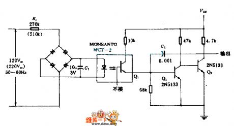
SCR automatic constant current charger circuit
Published:2011/5/24 2:31:00 Author:John | Keyword: automatic constant current charger
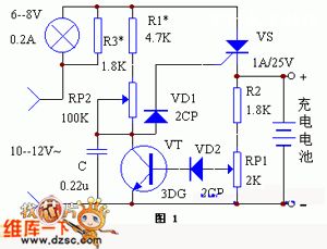
Principle of the circuit is shown in the figure. When it starts to charge, the voltage on two ends of the battery is low. Such is not enough to turn the transistor VT on. Phase-shift circuit formed by RC is to provide trigger current for SCR. The angle of phase-shift is determined by the RP2. SCR deadlines at negative half-cycle moment. Therefore, SCR charges by utilizing the half-wave silicon controlled rectifier to the battery generator. RP2 can be adjusted to adjust the charge current. The maximum charge current is set by R1. Indicating light is string in the circuit to indicate charging status and charge current. R3 is to adjust the brightness of light.
(View)
View full Circuit Diagram | Comments | Reading(4433)
Multi-purpose automatic charger circuit diagram
Published:2011/5/16 21:43:00 Author:Ecco | Keyword: Multi-purpose , automatic , charger
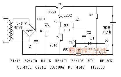
The circuit is designed for the single Ni-MH battery. In the figure: the electric supply is transformed by the transformer, rectified by the full-bridge, filtered by capacitor C1 and then it becomes DC current. LED1 is the power indicator, LED2 is the charging indicator light, T1 is the charging control transistor, which operates in the switching state; T2, T3 and capacitor C2 form a single stable trigger. R6 and RP constitutes a limited pressure sampling circuit, R7 is limiting the sampling resistor.
When the circuit gets power, if it does not connect to the battery, transistor T2 cuts off because of no base voltage, transistor T1 is also off, there is no voltage output. At this point only the power indicator light LED1 is lit.
(View)
View full Circuit Diagram | Comments | Reading(2205)
CD4060 Timing Ni-Cd battery charger circuit
Published:2011/5/9 1:58:00 Author:John | Keyword: Timing Ni-Cd battery charger
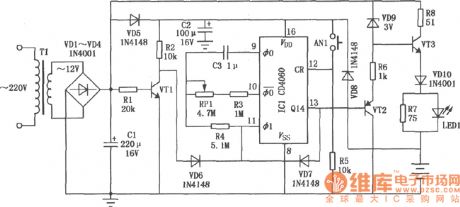
This circuit is a timing charger. The charging time can be adjusted from 5 to 25 hours. If power failure occurs in the charging process, the circuit has a function of cumulative timing. The circuit is available for recharging a 5 nickel-cadmium battery. (View)
View full Circuit Diagram | Comments | Reading(4669)
AC-209H battery charger circuit
Published:2011/5/9 1:59:00 Author:John | Keyword: battery charger
The diagram shown above is the AC-209H battery charger circuit. (View)
View full Circuit Diagram | Comments | Reading(991)
JDE-200 multi-function emergency power supply circuit diagram
Published:2011/5/11 1:47:00 Author:Ecco | Keyword: multi-function, emergency power supply
JDE-200 multi-function emergency power supply circuit diagram is shown as the chart.
(View)
View full Circuit Diagram | Comments | Reading(1388)
LM7806 formed full-automatic Nickel cadmium battery charging circuit diagram
Published:2011/5/9 0:16:00 Author:Crystal Liu | Keyword: full-automatic Nickel cadmium battery charging circuit

The charging circuit uses fold point voltage method to charge the nickel cadmium battery . When the battery is plentiful, charge current will be reduced to 8mA automaticly, meanwhile light diode indicates charging end,so it can not produce the phenomenon of overcharge and Owe filling,thus prolong life of the Nickel cadmium battery. (View)
View full Circuit Diagram | Comments | Reading(2545)
Constant current battery charger circuit
Published:2011/5/7 12:05:00 Author:John | Keyword: Constant current, battery charger

A three-terminal adjustable output voltage regulator can compose a variety of integrated battery chargers. Figure 1 is a constant current battery charger. The circuit is identical with the constant current source. As resistance for resistor R is 24Ω, the output current Io = 1.25/24 = 52mA. It means that 52mA constant current is used to charge the battery. Changes for resistance value of R can result in different charging current. (View)
View full Circuit Diagram | Comments | Reading(1192)
12V constant voltage battery charger circuit
Published:2011/5/7 12:12:00 Author:John | Keyword: constant voltage, battery charger
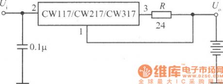
Figure 1 is a 12V constant voltage charger circuit. The circuit is the basically same with a constant power supply. Resistor R1 is 0.2Ω. R1 is used for limiting. It is equivalent to increase the internal resistance of the charger. The charging rate of the initial phase can be reduced. And integrated overcurrent protection on the regulator can be achieved. (View)
View full Circuit Diagram | Comments | Reading(1194)
current limiting battery charger circuit
Published:2011/5/7 12:28:00 Author:John | Keyword: battery charger, current limited protection
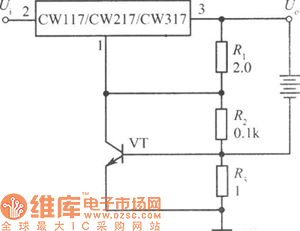
Figure 1 is a current limiting battery charger. VT transistor and resistor R3 form the limiting network. According to the figure, resistor R3 is a base-emitter power resistor of the transistor VT. It is connected in series with rechargeable batteries. Charging current flows through resistor R3. When the charge current is too large, the voltage drop on R3 exceeds 0.6V, the transistor VT can be conducted. As resistor R2 is in parallel with VT, the conduction of VT leads to the reduction of the equivalent parallel resistance. The output voltage Uo reduces and the output current decreases. So the purpose of limiting charging current is achieved. When taking R3 = lΩ), the maximum charge current is Iom = 0.6 / 1 = 0.6A. Select the R3 of a smaller resitance, so charging current can be larger. But the charging current can not exceed the maximum output current value of the integrated voltage regulator. (View)
View full Circuit Diagram | Comments | Reading(1305)
| Pages:11/13 12345678910111213 |
Circuit Categories
power supply circuit
Amplifier Circuit
Basic Circuit
LED and Light Circuit
Sensor Circuit
Signal Processing
Electrical Equipment Circuit
Control Circuit
Remote Control Circuit
A/D-D/A Converter Circuit
Audio Circuit
Measuring and Test Circuit
Communication Circuit
Computer-Related Circuit
555 Circuit
Automotive Circuit
Repairing Circuit