
Signal Processing
Index 58
The simple triangular wave switching sine wave circuit
Published:2011/8/11 8:15:00 Author:Borg | Keyword: triangular wave, sine wave
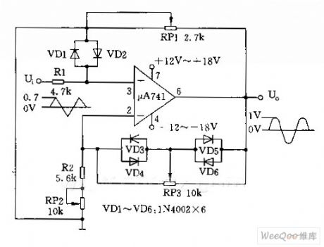
The simple triangular wave switching sine wave circuit is shown as above.
(View)
View full Circuit Diagram | Comments | Reading(2493)
AV source selector
Published:2011/8/11 22:43:00 Author:Ecco | Keyword: AV source selector
AV source selector circuit is composed of the power supply circuit, AV signal selection circuit and power control circuit, and it is shown in Figure 3-204. Power supply circuit is composed of the power transformer T, bridge rectifier UR, filter capacitors Cl5-C18 and three-terminal voltage regulator integrated circuit IC2. AV signal selection circuit is composed of the high-frequency analog switch integrated circuits ICl, resistors Rl-Rl5, capacitors Cl-C14 and the signal outlets XSl-XSl2. Power control circuit is composed of the selector switch S, transistors Vl-V3, relays Kl-K3, diodes VDl-VD3, LEDs VLl-VL3, resistors Rlg-R22 and the outlets XSl3-XSl7.
(View)
View full Circuit Diagram | Comments | Reading(964)
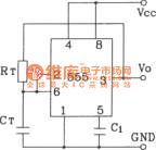
Direct self-excited feedback astable multivibrator circuit composed of 555
Published:2011/8/15 22:23:00 Author:Ecco | Keyword: Direct self-excited feedback, astable multivibrator , 555
View full Circuit Diagram | Comments | Reading(709)
Venturi Bridge Oscillation Circuit of LM377
Published:2011/8/3 6:44:00 Author:Michel | Keyword: Venturi Bridge, Oscillation Circuit
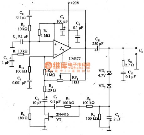
The picture 1 is Venturi bridge oscillation circuit of LM377.In the circuit,VT1 is used to limit the amplitude of the oscillating circuit and C3 and C6 are isolation capacitances.C5 is used to prevent high frequency oscillation.The series loop circuit composed of R2 and C2 and parallel loop circuit composed of R1 and C1 constitute postive feedback circuit.It can determine the oscillation frequency of the circuit.R10,R4,R6 and VT1 constitute negative feedback circuit and decides the limiting amplitude of the circuit.
When it is 10 KHz,the circuit distortion rate is lower than 1% and the distortion rate can be improved via adjusting the resistance value.According to the circuit parameters,the effective output voltage is 7.5V when it is 60Hz. (View)
View full Circuit Diagram | Comments | Reading(1424)
Explosion-proof electric motor soft starter
Published:2011/8/1 3:28:00 Author:chopper | Keyword: Explosion-proof, electric motor, soft starter
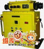
QJR1 mining explosion isolation and intrinsic safety motor soft starter(Soft starter for short) is a high-tech product produced by our company. It adopts advanced microprocessors, on-line control and power electronic control technology to achieve a soft start of motor to maximize the elimination of the mechanical and current shock and to extend the service life of equipments. It is the ideal replacement product for hydraulic coupling and other motor starting equipments, and it has advanced technology, safety, reliability, easy maintenance, long service life. (View)
View full Circuit Diagram | Comments | Reading(802)
Telephone electronic coded lock circuit
Published:2011/7/27 8:27:00 Author:Fiona | Keyword: electronic coded lock

Telephone electronic coded lock circuit is shown as above,the electronic coded lock is suitable for double audio circuits.After the phone adds this coded lock, when you call out,you must use the buttons on the phone to press the four pre-programmed password,then you can make a call.If the password is error, the phone can not dial out. When the exterior line is incoming call,the phone can receive the ring signal normally,picking machine can response.When the electronic coded lock circuitis connected toexterior line to be used,we mustmeasure the positive and negative polarities of outside feeder,then connect the positive pole to L1 and connect L2 to the negative pole,the phone is connected to the the phone location in electronic coded lock circuit.
(View)
View full Circuit Diagram | Comments | Reading(1788)
The medical electric aspirator waterproof controller (2)
Published:2011/8/3 22:23:00 Author:qqtang | Keyword: aspirator, waterproof controller
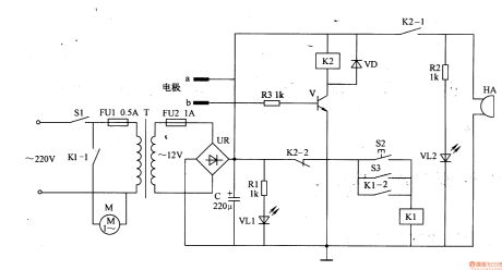
Working principle of the circuitThis medical electric aspirator waterproof controller consists of the power supply circuit, liquid level detection control circuit and alarm circuit, see as figure 9-47.
The power supply circuit consists of the switch S1, fusees FU1 and FU2, power supply transformer T, power supply indication LED VL1, rectifier bridge file UR, current limit resistor R1 and filter capacitor.
The liquid level test controller circuit consists of the test electrode a and b, resistor R3, transistor V, diode VD, control key S2, stepper switch and relay K1 and K2. (View)
View full Circuit Diagram | Comments | Reading(2131)
The spectrum therapeutic apparatus
Published:2011/8/3 22:26:00 Author:qqtang | Keyword: therapeutic apparatus
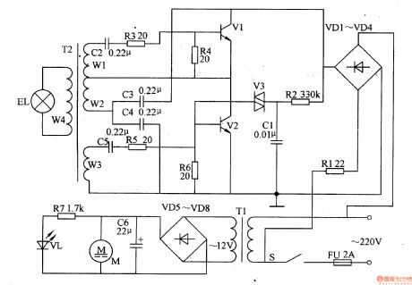
Here is to introduce a spectrum therapeutic apparatus which can generate 600-700mm red spectrum. After being concentrated, the red light is shed on the ill part of the human body, which can assist to cure many diseases.(this is often called burning electricity , which adopts the photochemical effect to cure illness). The working principle of the circuit The spectrum therapeutic apparatus consists of the power supply circuit and oscillating output circuit, see as figure 9-27.
The power supply circuit consists of the fuse FU, power supply switch S, rectifier diode VD1-VD8, power supply transformer T1, filter capacitor C6, resistor R1 and R7, power supply indicating LED VL and fan motor M. (View)
View full Circuit Diagram | Comments | Reading(1607)
The electric spark timer
Published:2011/8/3 22:29:00 Author:qqtang | Keyword: spark timer
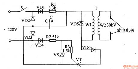
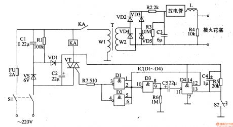
The electric spark timer introduced in the illustration can not only test the gravity acceleration, but also be used to illustrate the breakdown conducting experiment of the air in the high pressure or the combustible gas lighting experiment. The working principleThe electric spark timer circuit consists of the power supply switch S, diode VDl-VD6, the regulated diode VS, thyristor VT, resistor Rl-R3, capacitor C, booster transformer T and discharging pole, see as figure 8-55.
When the power supply switch S is getting through and it is in the forward half-cycle, the current runs through VD1, R1, C and VD3, and becomes a circuit, C is starting to charge. (View)
View full Circuit Diagram | Comments | Reading(1579)
The ordinary pressure boiler temperature auto controller
Published:2011/8/3 22:36:00 Author:qqtang | Keyword: ordinary pressure boiler, controller
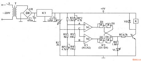
Here is to introduce the ordinary pressure boiler temperature auto controller which can automatically make the water pump work when the water in it reaches 85⁰C and stop working when the water is reduced to 50⁰C. The principle of the circuit The ordinary pressure boiler temperature auto controller consists of the power supply circuit, temperature detection control circuit, trigger, working state indicator circuit and control executing circuit, see as figure 8-154.
The temperature test controller circuit consists of the temperature sensor RT, resistor R1-R5, potentiometer RP1 and RP2, the op-amp integrated circuit IC (N1 and N2). (View)
View full Circuit Diagram | Comments | Reading(1069)
The welder power regulator
Published:2011/8/3 22:55:00 Author:qqtang | Keyword: welder, power regulator
The welder power adjuster in the example can adjust the output voltage and current by changing the thyristor conducting angle, it can be used in the restructuring of common welders.
The working principle of the circuitThe welder power regulator circuit consists of the control switch S, thyristor VT, dual-way trigger diode VRP, resistor R1-R3 and capacitors of C1 and V2, see as figure 8-16.
Pull the control switch S to the position of 1 , the welder will be in the non-controlled state, the output power of the welder is under the control of the power regulator circuit, at the moment, the welder is working in full voltage and the output current is the maximum. (View)
View full Circuit Diagram | Comments | Reading(3041)
The industrial electric igniter
Published:2011/8/3 22:39:00 Author:qqtang | Keyword: electric igniter
The industrial electric igniter introduced here characterizes the high igniting energy and low producing cost, etc, it can be used in industrial oil oven, or used to light the oil in chemical and petroleum area, or used in starting ignition when the gas is burning.The principle of the circuit The industrial electric igniter circuit consists of the power supply circuit, starting ignition control circuit and booster ignition circuit, see as figure 8-149.
The power supply consists of the switch S1, fuse FU, step-down capacitor C1, releasing resistor R1, rectifier diode VD1, voltage stabilizing diode VS and filter capacitor C2. (View)
View full Circuit Diagram | Comments | Reading(1529)
The industrial magnetic eraser
Published:2011/8/3 22:43:00 Author:qqtang | Keyword: industrial magnetic eraser
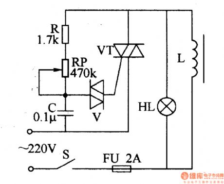
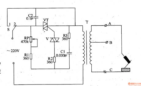
Here is to introduced an industrial magnetic eraser whose working voltage is AC 220V, it characterizes simple structure, high power, strong field and so on. The working principle of the circuit The industrial magnetic eraser consists of the fuse FU, thyristor VT, dual-way trigger diode V, magnetic erasing coil L, resistor R, potentiometer RP, capacitor C, indicator HL and power supply switch S , see as figure 8-148.
When the power supply switch S is getting through, the AC 220V voltage is charging C through FU, HL, L, R and RP. When C is charged to the regulated value, V is broken down, which makes VT to be triggered and conducting, HL is glowing. (View)
View full Circuit Diagram | Comments | Reading(987)
The pressure tank gas pressure exception alarm
Published:2011/8/3 22:59:00 Author:qqtang | Keyword: pressure tank, gas pressure, exception alarm
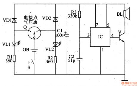
The working principle of the circuit The pressure tank gas pressure exception alarm circuit consists of the pressure detection control circuit, LED indicating circuit and audio alarm circuit, see as figure 8-145.
The gas pressure detection control circuit consists of the power supply switch S, battery GB and the electric connector air meter Q.The LED indicating circuit consists of the green LED VL1, red LED VL2 and the resistors of R1 and R2.The audio alarm circuit consists of the audio integrated circuit IC, transistor V, resistor R3, capacitors of C1 and C2, diodes of VD1 and VD2, loudspeaker BL. (View)
View full Circuit Diagram | Comments | Reading(864)
The heating magnetic mixer (1)
Published:2011/8/3 23:11:00 Author:qqtang | Keyword: magnetic mixer
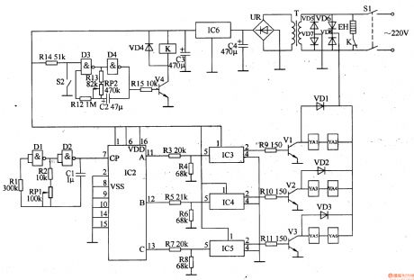
Here is to introduce the heating magnetic mixer which has the functions of timely constant temperature heating and auto mix with magnetic power, it can be used in mining industrial manufacturing and scientific experiments. The working principle of the circuitThe heating magnetic mixer consists of the power supply circuit, heating control circuit, clock oscillating circuit, pulse distribution controller and electromagnetic controller, see as figure 8-138.
The power supply circuit consists of the power supply switch S1, power transformer T, rectifier bridge pile UR, 3-terminal regulated integrated circuit IC6, filter capacitors C3 and C4. (View)
View full Circuit Diagram | Comments | Reading(1170)
800Hz Oscillator Circuit
Published:2011/8/2 1:31:00 Author:Joyce | Keyword: 800Hz, Oscillator
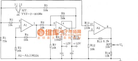
As shown in the figure is the 800 Hz oscillator characteristic of its simple circuit, high frequency accuracy and stable output level. It consists of four-operational amplifier integrated packages A1 ~ A3 (LM324) and tuning fork SJT (YYZ-2-800 Hz). When SJT produces 800 Hz oscillation signal feedback to the two-stage operational amplifier composed of A1 and A2 ,the signal is output by feet ⑦ of A2 . Then it will become positive feedback frequency signal after going through resistance R5, SJT .The 800 Hz signal will be amplified again by one-stage A3. Then the signal will be sent to potentiometer RP`s adjustable end (Uo) by A3`s feet ⑧ to become 800 Hz sine wave signal. Adjusting potentiometer RP can meet the requirement of output level of 0 dB / 600 Ω the output level, and the adjustable scope is ± 3 dB. (View)
View full Circuit Diagram | Comments | Reading(1616)
High Quality Low Frequency Signal Generator Circuit Composed of F007
Published:2011/8/2 1:31:00 Author:Joyce | Keyword: High Quality, Low Frequency , Signal , Generator
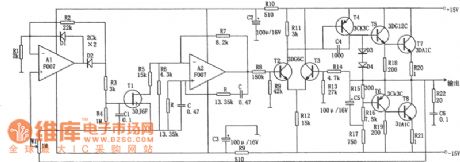
As shown in the figure is a high quality low frequency signal generator circuit characteristic of well-performed fixed amplitude, large output power and little wave distortion. It is a kind of ideal low frequency signal source. In the figure, operational amplifiers A and its feedback network constitute a typical venturi oscillator, whose oscillation frequency is:f0 = 1/2π RCA2 . The output end is connected with complementary push-pull power amplifier OCL to improve the load capacity of the circuit. Operational amplifier A1 is connected into a negative half-wave amplifier, and composes a negative feedback fixed amplitude circuit with W1, R4, C1, and T1 ect.
(View)
View full Circuit Diagram | Comments | Reading(1102)
10-gear Frequency Signal Generator Circuit
Published:2011/8/2 1:32:00 Author:Joyce | Keyword: 10-gear Frequency , Signal Generator
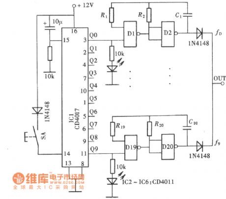
Usually, the general frequency signal generator is designed to have the whole frequency range which can be adjusted continuouslywhen in use. But in fact, the common test frequencies we use are only a few. The following frequency signal generator introduced has ten fixed frequency gears most commonly used, from which the user can choose according to his/her need. The frequency signal generator is composed of a digital gear switch and ten fixed frequency signal generator as shown in the figure. (View)
View full Circuit Diagram | Comments | Reading(954)
The Low noise sine wave crystal oscillator circuit
Published:2011/7/18 6:35:00 Author:Christina | Keyword: Low noise, sine wave, crystal oscillator

The Low noise sine wave crystal oscillator circuit is as shown:
(View)
View full Circuit Diagram | Comments | Reading(1341)
The Quartz crystal oscillator circuit
Published:2011/7/13 6:43:00 Author:Christina | Keyword: Quartz crystal, oscillator
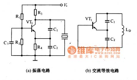
The oscillator that is composed of the quartz crystal can be divided into two kinds: the parallel resonant type crystal oscillator and the series resonant type crystal oscillator. The parallel resonant type crystal oscillator and the AC equivalent circuit of it are as shown in figure 1, if the quartz crystal is equivalent to the inductance LD, this circuit is the three-point capacitor oscillator, and only when the frequency is in the range of fo to f∞, the quartz crystal will present the inductance characteristics.
Figure 1 The parallel resonant type crystal oscillator and the AC equivalent circuit
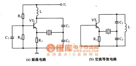
Figure 2 shows the series resonant type crystal oscillator circuit and the AC equivalent circuit of it.
Figure 2 The series resonant type crystal oscillator circuit and the AC equivalent circuit
(View)
View full Circuit Diagram | Comments | Reading(2657)
| Pages:58/195 At 204142434445464748495051525354555657585960Under 20 |
Circuit Categories
power supply circuit
Amplifier Circuit
Basic Circuit
LED and Light Circuit
Sensor Circuit
Signal Processing
Electrical Equipment Circuit
Control Circuit
Remote Control Circuit
A/D-D/A Converter Circuit
Audio Circuit
Measuring and Test Circuit
Communication Circuit
Computer-Related Circuit
555 Circuit
Automotive Circuit
Repairing Circuit