
Oscillator Circuit
Index 48
BASIC_LM3909_AUDIO_OSCILLATOR
Published:2009/6/22 23:42:00 Author:May
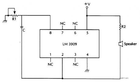
The LM3909's oscillator frequency can be fine-tuned by adding a resistor to a basic circuit. (View)
View full Circuit Diagram | Comments | Reading(942)
ONE_TRANSISTOR_PHASE_SHIFT_OSCILLATOR
Published:2009/6/22 23:41:00 Author:May
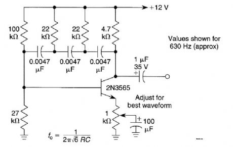
A single transistor is used as an active element in an RC phase shift oscillator. (View)
View full Circuit Diagram | Comments | Reading(2696)
QUAD_TONE_OSCILLATOR
Published:2009/6/22 23:40:00 Author:May
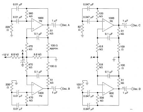
A quad op amp (TL084, etc.) can be used to produce four audio tone generators for use in a test setup. The circuit uses a 12-V supply. (View)
View full Circuit Diagram | Comments | Reading(0)
EASILY_TUNED_SINE_WAVE_OSCILLATOR
Published:2009/6/22 23:39:00 Author:May
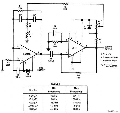
The circuit will provide both a sine-and square-wave output for frequencies from below 20 Hz to above 20 kHz. The frequency of oscillation is easily tuned by varying a single resistor. This is a considerable advantage over Wien bridge circuits, where two elements must be tuned simultaneously to change frequency. Also, the output amplitude is relatively stable when the frequency is changed.An operational amplifier is used as a tuned circuit, driven by square wave from a voltage comparator. Frequency is controlled by R1, R2, C1, C2, and R3, with R3 used for tuning. Tuning the filter does not affect its gain or bandwidth, so the output amplitude does not change with frequency. A comparator is fed with the sine-wave output to obtain a square wave. The square wave is then fed back to the input of the tuned circuit to cause oscillation. Zener diode, D1, stabilizes the amplitude of the square wave fed back to the filter input. Starting is ensured by R6 and C5, which provide dc negative feedback around the comparator. This keeps the comparator in the active region (View)
View full Circuit Diagram | Comments | Reading(0)
Low cost Wien oscillator composed of F007
Published:2011/7/28 3:16:00 Author:Ecco | Keyword: Low cost , Wien oscillator
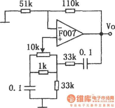
The chart shows the low cost Wien oscillator circuit. One hand, the circuit can avoid the problem of having to adopt expensive inductors in the general oscillator circuits. On the other hand,it can also avoid using double-potentionmeter to adjust frequency in the Wien bridge oscillators. It only uses a potentiometer to adjust the frequency, so the cost is lower. The adjusting frequency range is small, although there are some defects, it can still be used when it needs small frequency range, and the circuit is stable. (View)
View full Circuit Diagram | Comments | Reading(685)
Wien bridge sine-wave generator
Published:2011/7/28 2:19:00 Author:Ecco | Keyword: Wien bridge , sine-wave, generator
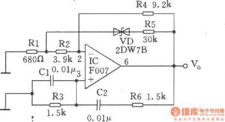
Oscillation frequency of the circuit shown in the figure is about lkHz, and it uses the regulator 2DW78 to stabilize amplitude. Ifl. 5kΩ resistors in the bridge isreplaced bycoaxial double potentiometer, the band switch needs to access different capacitors, the output signal frequency can be adjusted continuously. The maximum frequency of oscillation circuit is decided by the characteristics of operational amplifier F007. And the greater resistance, capacitance on low frequency end will cause instability or leakage, so the input impedance of operational amplifier should be as high as possible.
(View)
View full Circuit Diagram | Comments | Reading(951)
SWEEP_FUNCTION_GENERATOR_1
Published:2009/6/19 3:17:00 Author:May
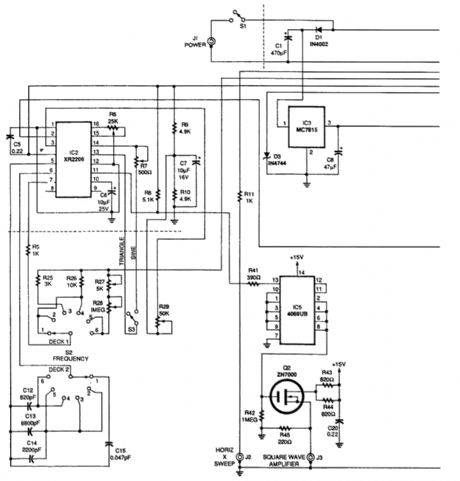
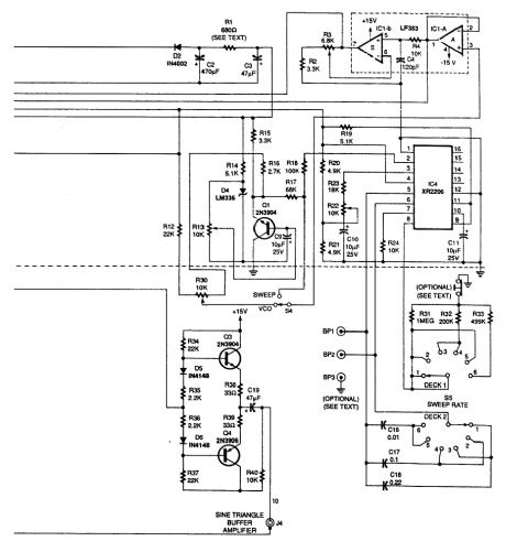
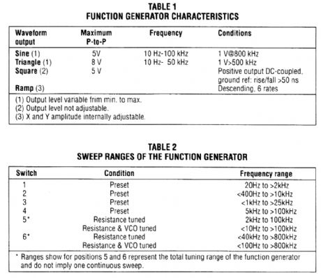
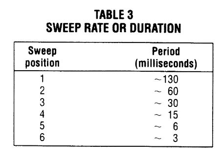
Both IC2 and IC4 are Exar XR2206 monolithic function generators; IC4 functions as a ramp gen-erator, and IC2 functions as a generator of sine, triangular, and square waveforms. Dual operational amplifier IC1 produces a scaled, level-shifted ramp output that is capable of deflecting an oscillo-scope's horizontal sweep.Any frequency of interest along the horizontal axis of an oscilloscope that is coupled to this func-tion generator can be mgasured with an external frequency counter by manually tuning the function generator's VCO instead of sweeping it. The performance characteristics of the sweep/function gen-erator are summarized in the Table.The generator's sweep rate and frequency can be set by front-panel rotary six-position switches, Sweep Rate Switch S5 and Frequency Switch S2. The VCO control R30 manually tunes the VCO.Table 2 lists the sweep ranges of the function generator. Sweep ranges not covered in ranges 1 to 4 can be set up as required on positions 5 and 6. Selecting the VCO setting on the front panel toggle switch S4 permits tuning any fixed frequency within the total frequency range of the instrument with both frequency switch S2 and VCO control R30.The sweep rate or duration of the sweep ramp is selected by the rotary six-position Sweep Rate Switch S5. Table 3 lists the sweep rate durations for each of the six positions. Longer periods should be used for lower frequency sweeps. (View)
View full Circuit Diagram | Comments | Reading(4692)
GATE_DIP_OSCILLATOR_II
Published:2009/6/19 3:17:00 Author:May
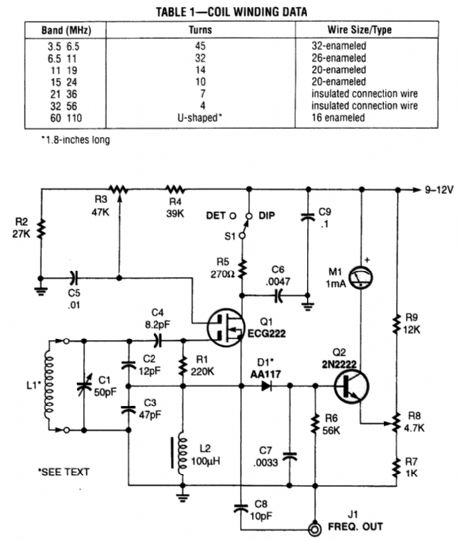
Useful for measuring the resonant frequencies of antennas, tuned circuits, and also as a tuned detector, this circuit is a modem variation of the classic vacuum tube grid dip oscillator. It coupled the G.D.O. to a tuned circuit and caused RF energy to be absorbed by the unknown tuned ctrcutt when the G.D.O. frequency was the same as that of the tuned circuit in question. This showed as a dip in the meter reading. (View)
View full Circuit Diagram | Comments | Reading(2739)
GATE_DiP_OSCILLATOR_I
Published:2009/6/19 3:00:00 Author:May

The typical dip meter is comprised of a tuning coil,RE oscillator,a detector,and a meter as shown in A.When the meter's tuning coil is coupled to a tuned circuit resonating at the same fre-quency as the GDM,the reading dips (C).The GDM's tuning coil can be coupled to the coaxial feed line of an antenna through a few(perhaps 2 to 3)turns of wire,and used to determine the antenna's resonant frequency(D). (View)
View full Circuit Diagram | Comments | Reading(1853)
AUTO_BATTERY_ISOLATOR_CIRCUIT
Published:2009/6/19 2:39:00 Author:May
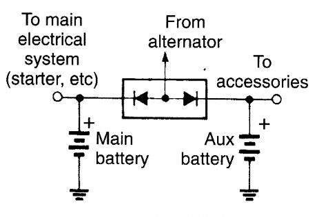
The diodes ensure that current can flow in both batteries from the altemator, but the main battery can't feed the accessory system, nor vice versa. (View)
View full Circuit Diagram | Comments | Reading(934)
SQUARE_WAVE_OSCILLATOR
Published:2009/6/18 23:28:00 Author:May
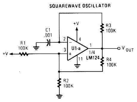
An Op amp with positive feedback generatesa square wave. The period ofthe oscillator is determined by R3 and C1.T=T1 + T2 ≈0.69×2 (R3C1) T1=T2 (View)
View full Circuit Diagram | Comments | Reading(1)
SIREN_OSCILLATOR
Published:2009/6/18 23:25:00 Author:May
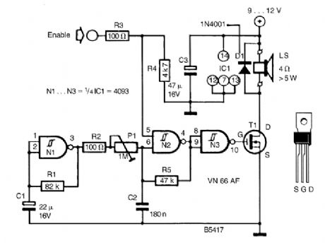
A CD4093 chip and a few components make up a siren oscillator, which drives power MOSFET T1. A 4-Ω speaker is driven directly from this device. The siren is enabled by a logic high applied to the ENABLE input. (View)
View full Circuit Diagram | Comments | Reading(3211)
WIEN_BRIDGE_SINE_WAVE_OSCILLATOR
Published:2009/6/18 21:43:00 Author:May

This Wien-bridge sine-wave oscillator uses a 2N3819 as an amplitude stabilizer. The 2N3819 acts as a variable-resistance element in the Wien bridge. (View)
View full Circuit Diagram | Comments | Reading(2)
SIMPLE_SINE_WAVE_OSCILLATOR
Published:2009/6/18 21:42:00 Author:May
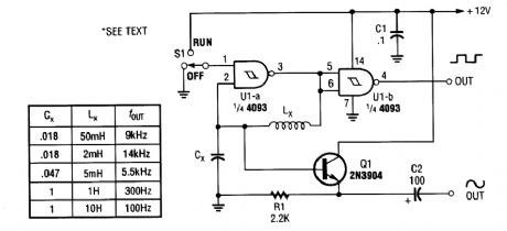
Using an LC circuit,this CMOS oscillator generates slne waves. (View)
View full Circuit Diagram | Comments | Reading(2093)
HAM_BAND_VFO
Published:2009/6/18 3:54:00 Author:May
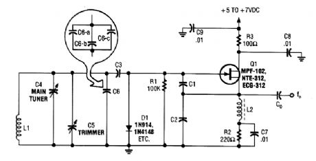
This basic VFO for the 3- to 6-MHz range is commonly used in amateur applications, using a Col-pitts circuit. For 5 to 5.5 MHz, C1 = C2 = 70 pF and for 3.5 to 4.0 MHz, use 1000 pF. C3 is typically 10 to 220 pF, depending on the frequency. C4, C5, and C6, together with C3, determine the frequency along with L1. C6 can be made up of several smaller values, paralleled to get the exact required value. (View)
View full Circuit Diagram | Comments | Reading(1010)
A_SHORTWAVE_PULSED_MARKER_OSCILLATOR
Published:2009/6/18 3:52:00 Author:May
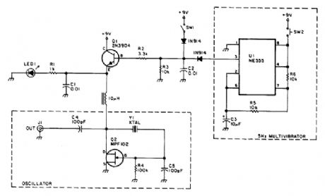
A useful marker oscillator can be made using an NE555 to pulse the oscillator at an audio rate. This makes it easy to find the signal in the presence of interference. The crystal can be any suitable frequency from 1 to 30 MHz. (View)
View full Circuit Diagram | Comments | Reading(813)
NE6O2_RF_OSCILLATOR_CIRCUITS
Published:2009/6/18 3:50:00 Author:May
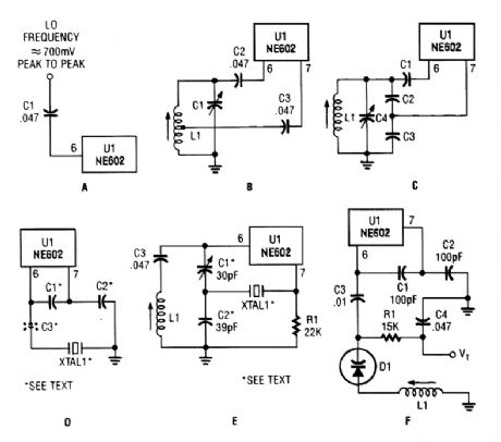
Just about any standard oscillator (such as a Colpitts or Hartley configuration) can be used to generate the LO (local oscillator) frequency needed by the NE602. (View)
View full Circuit Diagram | Comments | Reading(934)
65_MHz_VFO
Published:2009/6/18 2:40:00 Author:May
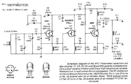
Fixed-value capacitors are disc ceramics. C1, C4, C5, C6, and C8 are NPO ceramic or polystyrene. C2 is a 25-pF ceramic trimmer and C3 is a 15-pF miniature air variable capacitor. The resistors are 1/4-W carbon film or composition. The RE chokes are miniature Mouser Electronics No. 43LR103 units. For L1, use 32 turns of #28 enamel wire on an Amidon Assoc. T50-6 (yeltow) toroid. L2 has 25 turns of #28 enamel wire on an Amidon Ft-37-61 ferrite toroid. (View)
View full Circuit Diagram | Comments | Reading(1243)
SINGLE_TRANSISTOR_CODE_PRACTICE_OSCILLATOR
Published:2009/6/17 3:01:00 Author:May
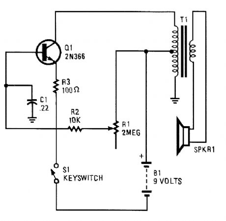
A 2N366 is configured as an audio feedback oscillator using an audio transformer is shown. Adjust R1 for proper operation and desired audio note. (View)
View full Circuit Diagram | Comments | Reading(2330)
VARIABLE_FREQUENCY_CODE_PRACTICE_OSCILLATOR
Published:2009/6/17 2:59:00 Author:May
The variable frequency audio oscillator can be used as a low-level alarm sounder or a codepractice oscillator. (View)
View full Circuit Diagram | Comments | Reading(1110)
| Pages:48/54 At 204142434445464748495051525354 |
Circuit Categories
power supply circuit
Amplifier Circuit
Basic Circuit
LED and Light Circuit
Sensor Circuit
Signal Processing
Electrical Equipment Circuit
Control Circuit
Remote Control Circuit
A/D-D/A Converter Circuit
Audio Circuit
Measuring and Test Circuit
Communication Circuit
Computer-Related Circuit
555 Circuit
Automotive Circuit
Repairing Circuit