
Oscillator Circuit
Index 40
LOW_FREaUENCY_CRYSTAL_OSCILLATOR_10kHz_to_150_kHz
Published:2009/7/1 3:38:00 Author:May
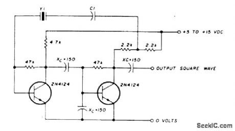

C1 in series with the crystal may be used to adjust the oscillator output frequency. Value may range between 20 pF and 0.01 μF, or may be a trimmer capacitor and will approximately equal the crystal load capacitance. X values are approximate and can vary for most circuits and frequencies; this is also true for resistance values. Adequate power supply decoupling is required; local decoupling capacitors near the oscillator are recommended. All leads should be extremely short in high frequency circuits. (View)
View full Circuit Diagram | Comments | Reading(911)
CRYSTAL_OSCILLATOR_PROVIDES_LOW_NOISE
Published:2009/7/1 3:35:00 Author:May
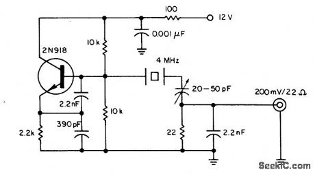
The oscillator delivers an output of high spectral purity without any substantial sacrifice of the usual stability of a crystal oscillator. The crystal in addition to determining the oscillator's frequency, is used also as a low-pass filter for the unwanted harmonics and as a bandpass filter for the sideband noise. The noise bandwidth is limited to less than 100 Hz. All higher harmonics are substantially suppressed-60 dB down for the third harmonic of the 4-MHz fundamental oscillator frequency. (View)
View full Circuit Diagram | Comments | Reading(869)
IC_COMPATIBLE_CRYSTAL_OSCILLATOR
Published:2009/7/1 3:33:00 Author:May
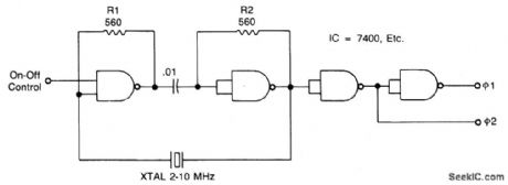
Resistors R1 and R2 temperature-stabilize the NAND gates; they also ensure that the gates are in a linear region for starting. Capacitor C1 is a dc block; it must have less than1/10 ohm impedance at the operating frequency. The crystal runs in a series-resonant mode. Its series resistance must be low; AT-cut crystals for the 1-to 10-MHz range work well. The output waveshape has nearly a 50% duty cycle, with chip-limited rise times. The circuit starts well from 0°to 70℃. (View)
View full Circuit Diagram | Comments | Reading(940)
PIERCE_CRYSTAL_OSCILLATOR
Published:2009/7/1 3:22:00 Author:May


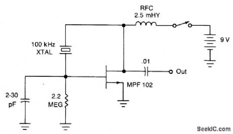
The JFET Pierce oscillator is stable and simple. It can be the clock of a microprocessor, a digital timepiece or a calculator. With a probe at the output, it can be used as a precise injection oscillator for troubleshooting. Attach a small length of wire at the output and this circuit becomes a micropower transmitter. (View)
View full Circuit Diagram | Comments | Reading(3206)
1_MHz_FET_CRYSTAL_OSCILLATOR
Published:2009/7/1 3:21:00 Author:May
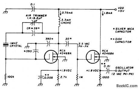
This stable oscillator circuit exhibits less than 1 Hz frequency change over a VDD range of 3-9 volts. Stability is attributed to the use of MOSFET devices and the use of stable capacitors. (View)
View full Circuit Diagram | Comments | Reading(2359)
CRYSTAL_OSCILLATOR
Published:2009/7/1 3:16:00 Author:May
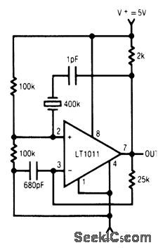
This circuit uses an LT1011 comparator biased in its linear mode and a crystal to establish its resonant frequency. This circuit can achieve a few hundred kHz, temperature independent clock frequency with nearly 50% duty cycle. (View)
View full Circuit Diagram | Comments | Reading(0)
CRYSTAL_CONTROLLED_LOCAL_OSCILLATOR_FOR_SSB_TRANSMITTER
Published:2009/7/1 3:15:00 Author:May
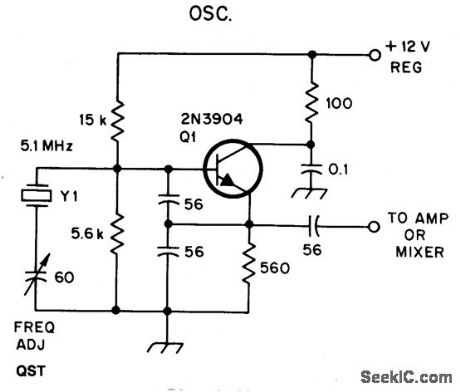


This oscillator may contain several switched crystals to provide channelized operation.A buffer amplifter may be added, if desired.
(View)
View full Circuit Diagram | Comments | Reading(920)
LOW_POWER,_5_V_DRIVEN,TEMPERATURE_COMPENSATED_CRYSTAL_OSCILLATOR(TXCO)
Published:2009/7/1 3:13:00 Author:May
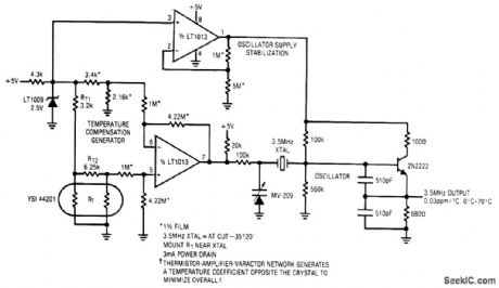
View full Circuit Diagram | Comments | Reading(842)
10_MHz_CRYSTAL_OSCILLATOR
Published:2009/7/1 3:11:00 Author:May


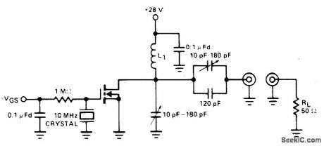
This xtal oscillator is a FET equivalent of a vacuum tube tuned to plate-tuned grid xtaloscillator. Feedback is via the drain to gate capacitance. (View)
View full Circuit Diagram | Comments | Reading(1066)
VARACTOR_TUNED_10_MHz_CERAMIC_RESONATOR_OSCILLATOR
Published:2009/7/1 3:09:00 Author:May
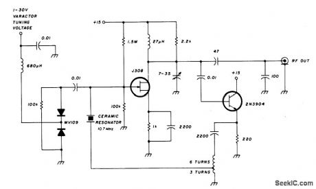
The FET input amplifier has fixed bias with source feedback. This provides a very high input impedance with very low capacitance. The FET amplifier drives an emitter follower which, in spite of the fact that it has a low output impedance, feeds a transformer with a 3:1 turns ratio for a nine-fold impedance reduction. The result is an impedance at the ceramic resonator of a few ohms maximum. The varactor-tuned ceramic resonator oscillator has a significant frequency-temperature coefficient. The tuning range of the VCO is approximately 232 kHz, with a temperature coefficient of 350 Hz per degree centigrade. When using this circuit as a VCO, the entire 232 kHz range cannot be used because some of the tuning range must be sacrificed for the temperature dependence.If the required tuning range were 200 kHz, leaving 32 kHz for temperature variation, the resulting temperature variation would be more than 90℃. (View)
View full Circuit Diagram | Comments | Reading(1946)
EMITTER_COUPLED_RC_OSCILLATOR
Published:2009/7/1 2:34:00 Author:May
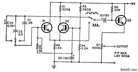
The circuit covers 15 Hz-30 kHz and is useful as a function generator. The 2N2926 or equivalent transistors can be used. (View)
View full Circuit Diagram | Comments | Reading(856)
LINEAR_TRIANGLE_SQUARE_WAVE_VCO
Published:2009/7/1 2:13:00 Author:May
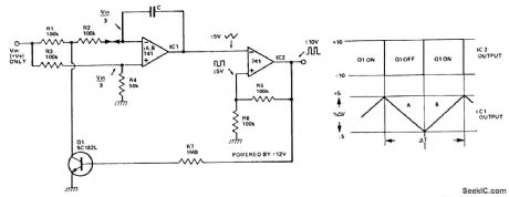
The VCO has two buffered outputs; a triangle wave and a square wave. Frequency is dependent on the output voltage swing of the Schmitt trigger, IC2. Superior performance can be obtained by replacing Q1 with a switching FET. Fast FET op amps will improve high frequency performance. (View)
View full Circuit Diagram | Comments | Reading(4023)
HIGH_DRIVE_OSCILLATOR_FLSHER
Published:2009/6/30 23:34:00 Author:May
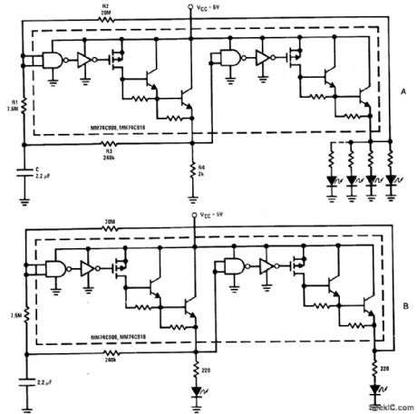
The driver in the package is connected as a Schmitt trigger oscillator (A) where R1 and R2 are used to generate hysteresis. R3 and C are the inverting feedback timing elements and R4 is the pull-down load for the first driver. Because of its current capability, the circuit can be used to drive an array of LEDs or lamps. If resistor R4 is replaced by an LED (plus a current limiting resistor), the circuit becomes a double flasher with the 2 LEDs flashing out of phase (B). (View)
View full Circuit Diagram | Comments | Reading(719)
LOW_FREQUENCY_OSCILLATOR_FLASHER
Published:2009/6/30 23:29:00 Author:May
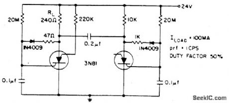
Electrolytic capacitors are unnecessary to generate a 1 cps frequency. As an scs triggers on, the 0.2 μF commutating capacitor turns off the other one and charges its gate capacitor to a negative potential. The gate capacitor charges towards 24 volts through 20 M retriggering its scs. Battery power is delivered to the load with 88% efftciency.The 20 M resistors can be varied to change prf or duty fact (View)
View full Circuit Diagram | Comments | Reading(839)
2_MHz_CRYSTAL_USING_CMOS_PAIR
Published:2009/6/30 23:13:00 Author:May
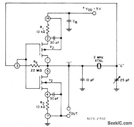
One CMOS transistor pair from CA3600E array is connected with feedback pinetwork to glve sta-ble oscilIator performance with 2-MHz crystal.Low power drain makes circuit ideal for use in digital clocks and watches.- Linear Integrated Circuits and MOS/FET's, RCA Solid State Divi-sion, Somerville, NJ, 1977, p 280. (View)
View full Circuit Diagram | Comments | Reading(782)
RE_OSCILLATOR
Published:2009/6/30 3:05:00 Author:May
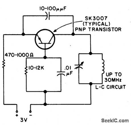
This rf oscillator is useful up to 30 MHz.An SK 3007 PNP transistor is recommended. (View)
View full Circuit Diagram | Comments | Reading(894)
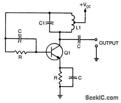
COLPITTS_OSCILLATOR
Published:2009/6/30 3:04:00 Author:May
When calculating its resonan frequency,use C1C2/C1+C2 for the total capacitance ofthe L-C circuit. (View)
View full Circuit Diagram | Comments | Reading(0)
27_MHz_AND_49_MHz_RE_OSCILLATOR_TRANSMITTER
Published:2009/6/30 3:00:00 Author:May
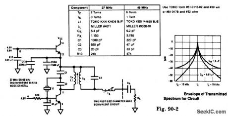
The modulator and oscillator consist of two NPN transistors. The base of the modulator transistor is driven by a bidirectional current source with the voltage range for the high condition limited by a saturating PNP collector to the pin 4 VREG voltage and low condition limited by a saturating NPN collector in series with a diode to ground. The crystal oscillator/transmi tter transistor is configured to oscillate in a class C mode. Because third overtone crystals are used for 27 MHz or 49 MHz applications a tuned collector load must be used to guarantee operation at the correct frequency. (View)
View full Circuit Diagram | Comments | Reading(1641)
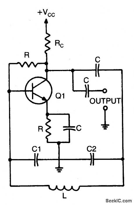
HARTLEY_OSCILLATOR
Published:2009/6/29 4:41:00 Author:May
Resonant frequency is 1/2 π √LIC1. (View)
View full Circuit Diagram | Comments | Reading(0)
2_MHz_OSCILLATOR_
Published:2009/6/29 4:37:00 Author:May
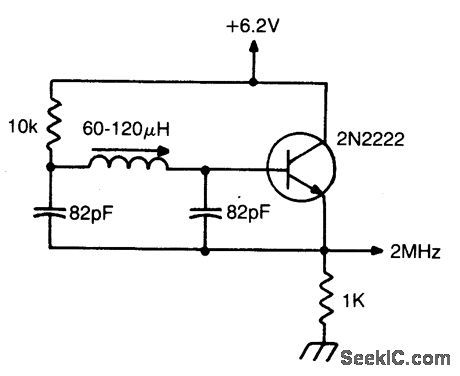
Miller 9055 miniature slugtuned coil;allresistors 1/4W 5%;all caps mln.25 V ceramic. (View)
View full Circuit Diagram | Comments | Reading(863)
| Pages:40/54 At 202122232425262728293031323334353637383940Under 20 |
Circuit Categories
power supply circuit
Amplifier Circuit
Basic Circuit
LED and Light Circuit
Sensor Circuit
Signal Processing
Electrical Equipment Circuit
Control Circuit
Remote Control Circuit
A/D-D/A Converter Circuit
Audio Circuit
Measuring and Test Circuit
Communication Circuit
Computer-Related Circuit
555 Circuit
Automotive Circuit
Repairing Circuit