
Oscillator Circuit
Index 23
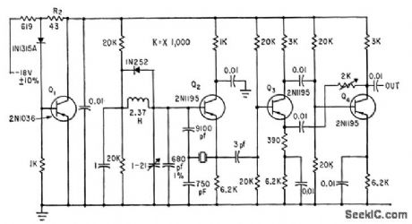
TWO_STAGE_VARIABLE_FREQUENCY_CRYSTAL_OSCILLATOR
Published:2009/7/19 21:03:00 Author:Jessie
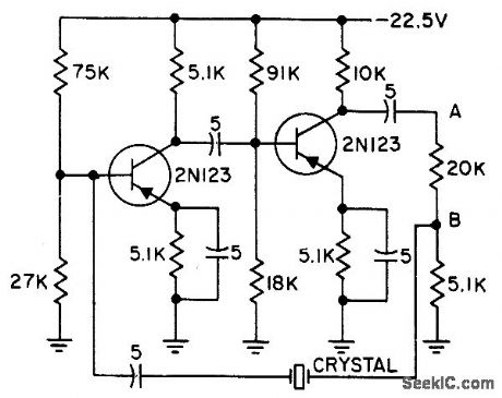
Operates at 9.1 kc with long-term frequency stability of a few parts per million. Frequency can be pulled up to 5 cps off resonance by adjusting trimmer capacitor in series with crystal. Used in analog and digital systems to achieve calibration by deviating carrier frequency a small but accurately known amount.-G. A. Gedney and G. M. Davidson, Crystal Oscillator has Variable Frequency, Electronics, 31:7, p 118-119. (View)
View full Circuit Diagram | Comments | Reading(1045)
STABLE_1_MC_OSCILLATOR
Published:2009/7/19 21:02:00 Author:Jessie
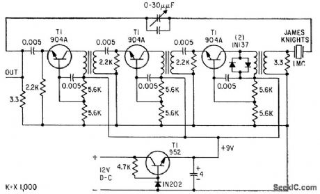
Gives frequency stability of one part in 1 billion per day at normal room temperature, at which a 12-Ib, 45-V battery can furnish crystal oven and circuit power for 72 hours.-J. F. Mercurio, Jr., Stable, Low-Cost One-Mc Oscillator, Electronics, 32:6, p 50-51. (View)
View full Circuit Diagram | Comments | Reading(698)
2000_MC_GENERATOR
Published:2009/7/19 21:42:00 Author:Jessie
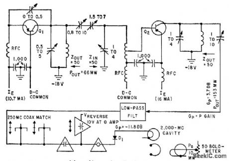
Depends on harmonic frequency conversion. Oscillator Q1 and amplifier Q2 deliver 153 mw at 250 Mc to coaxial matching section. Despite conversion loss of 11.8 db in 8th-harmonic generator D1, output of 10 mw at 2,000 Mc appears across 50-ohm bolometer.-M. M. Fortini and J. Vilms, Solid-State Generator for Microwave Power, Electronics, 32:36, p 42-43. (View)
View full Circuit Diagram | Comments | Reading(875)
FREQUENCY_SHIFT_KEYED_OSCILLATOR
Published:2009/7/19 21:40:00 Author:Jessie
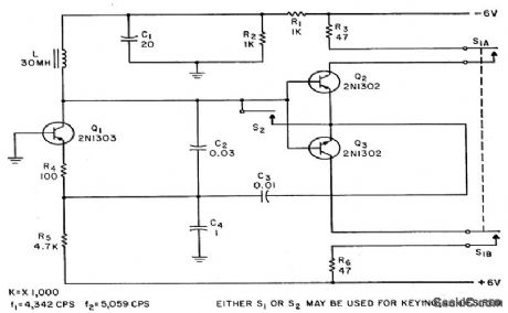
Q1 is Colpitts oscillator at 5 kc and Q2-Q3 is push-pull complementary-emitter amplifier with unity voltage gain. Either switch shorts amplifier, thereby increasing tuning capacitance enough to shift frequency 1 kc.-N. C. Hekimian, Getting Rid of Transients in Frequency-Shift Keying, Electronics, 35:45, p 58-59. (View)
View full Circuit Diagram | Comments | Reading(871)
12_22_Mc_VOLTAGE_CONTROLLED_OSCILLA_TOR
Published:2009/7/19 21:38:00 Author:Jessie
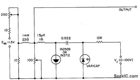
Voltage-variable capacitor tunes tunnel-diode oscillator electronically.- Transistor Manual, Seventh Edition, General Electric Co., 1964, p 350. (View)
View full Circuit Diagram | Comments | Reading(740)
3_260_MC_TUNNEL_DIODE_OSCILLATOR
Published:2009/7/19 21:37:00 Author:Jessie
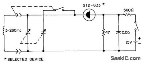
Uses plug-in coils to generate sine-wave output over wide frequency range.- Transistor Manual, Seventh Edition, General Electric Co., 1964, p 352. (View)
View full Circuit Diagram | Comments | Reading(764)
UNSTABILIZED_TUNNEL_DIODE
Published:2009/7/19 21:35:00 Author:Jessie
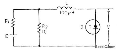
Simple but generally impractical because frequency varies greatly with supply voltage and waveform is poor, Frequency also varies with bias, from maximum of 2 Mc at 250 mv to 0.5 Mc at 80 mv and to 0.8 Mc of 400 mv. -Wen-Hsiung Ko, Designing Tunnel Diode Oscillators, Electronics, 34:6, p 68-72. (View)
View full Circuit Diagram | Comments | Reading(785)
SCS_RLC_OSCILLATOR
Published:2009/7/19 21:34:00 Author:Jessie
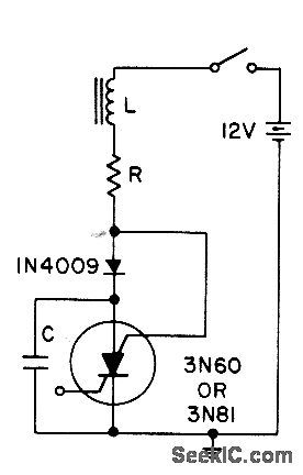
Positive transient, such as closing of switch, charges C through L. When current reverses, diode blocks and triggers scs. When capacitor discharges, scs turns off and C charges to repeat cycle.- Transistor Manual, Seventh Edition, General Electric Co., 1964, p 434. (View)
View full Circuit Diagram | Comments | Reading(831)
RING_OF_FIVE_NEON_OSCILLATOR
Published:2009/7/19 21:33:00 Author:Jessie
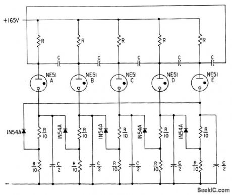
Can be used for sequential switching, with operating cycles of various lengths at audio and subaudio frequencies. When first turned on, one of lamps fires because of inequalities in lamp properties, and others then fire in sequence. Values of R and C determine cycle duration, according to formula given in article. Time is 1 sec for C=0.5 mfd and R=10 meg.-R. L. lves, Neon Oscillator Rings, Electronics, 31:41, p 108-115. (View)
View full Circuit Diagram | Comments | Reading(898)
STABLE_3_MC_CRYSTAL_COLPITTS
Published:2009/7/19 21:32:00 Author:Jessie
Crystal operates at series resonance in feedback path between emitter of Q2 and tank tap. Q1 is shunt voltage regulator providing power-supply isolation. Two-stage feedback amplifier Q3-Q4 provides output impedance of about 150 ohms when R1 is adjusted for 0.5-V peak-to-peak output swing.-J. W. Hamblen and J. B. Oakes, Instrumentation and Telemetry of Transit Navigational Satellites, Electronics, 34:32, p 148-153. (View)
View full Circuit Diagram | Comments | Reading(729)
SQUARE_WAVE_OSCILLATOR
Published:2009/7/10 4:02:00 Author:May
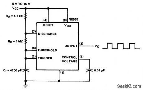
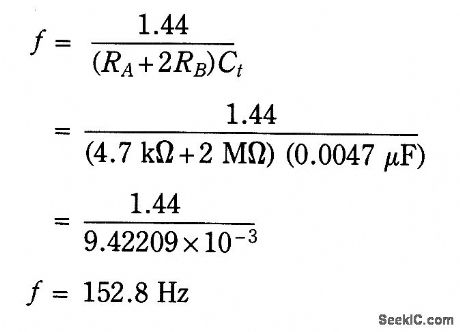
The NE555 is connected in the astable mode and uses only three timing components (RA, RB, and Ct. A 0.01-μF bypass capacitor is used on pin 5 for noise immunity. The operating restrictions of the astable mode are few. The upper frequency limit is about 100 kHz for reliable operation, as a result of internal storage times. Theoretically, it has no lower frequency limit, only that which is imposed by Rt and Ct limitations. The frequency for the circuit can be calculated as: (View)
View full Circuit Diagram | Comments | Reading(0)
PREFERRED_08_20_MC_ELECTRON_COUPLED_COLPITTS_CRYSTAL
Published:2009/7/19 21:30:00 Author:Jessie
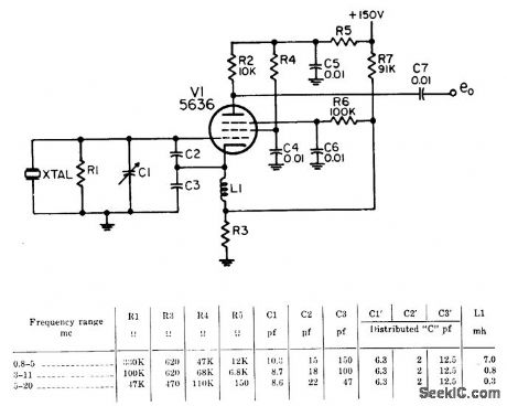
Provides higher output, greater harmonic content, better frequency correlation, and more immunity from effects of load changes than simpler Colpitts version. –NBS, Handbook Preferred Circuits Navy Aeronautical Electronic Equipment, Vol. 1. Electron Tube Circuits, 1963, PC 102, p 102-2. (View)
View full Circuit Diagram | Comments | Reading(842)
CODE_PRACTICE_OSCILLATOR_1
Published:2009/7/19 21:28:00 Author:Jessie
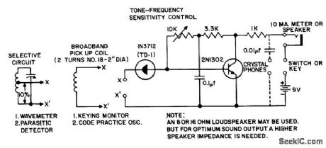
Basic tunnel-diode oscillator with single-transistor amplifier stage can be used as code practice oscillator, sensitive broadband c-w keying monitor, sensitive aural-visual parasitic detector, or as wavemeter. - Transisyor Manual, Seventh Edition, General Electric Co., 1964, p 362. (View)
View full Circuit Diagram | Comments | Reading(0)
PREFERRED_08_20_MC_COLPITTS_CRYSTAL
Published:2009/7/19 21:27:00 Author:Jessie
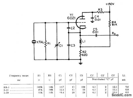
Frequency is changed by substituting plug in crystals. Component values depend on frequency range. Serves as simple and stable frequency source.-NBS, Handbook Preferred Circuits Navy Aeronautical Electronic Equipment, Vol. I, Electron Tube Circuits, 1963, PC 101, p 101-2. (View)
View full Circuit Diagram | Comments | Reading(713)
SIMPLE_SQUARE_WAVE_OSCILLATOR
Published:2009/7/10 3:55:00 Author:May
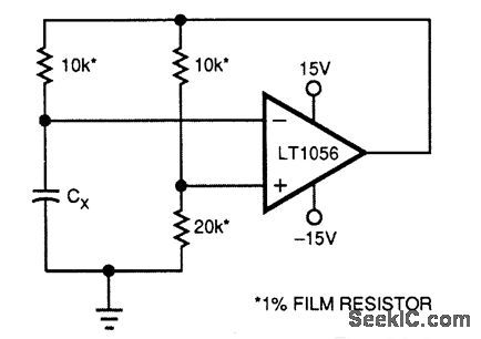
Using only four components, this circuit generates a square wave. Oscillation frequency is ≈ 1/ RCx Hz, R=MΩ, Cx-μF (in this case, R=10 kΩ). (View)
View full Circuit Diagram | Comments | Reading(718)
CONSTANT_OUTPUT_OSCILLATOR
Published:2009/7/19 21:26:00 Author:Jessie
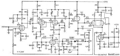
Used with automatic doppler cycle counter to determine position and velocity of missiles and satellites. Output signal amplitude is maintained constant over wide range of maintained constant over wide range of frequencies. –B. E. Keiser, Digital-Counter Techniques Increase Doppler Uses, Electronics, 32:21, p 46-50. (View)
View full Circuit Diagram | Comments | Reading(788)
10_CPS_PHASE_SHIFT_FET_OSCILLATOR
Published:2009/7/19 21:23:00 Author:Jessie
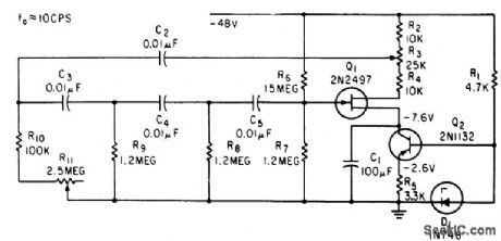
Uses four-mesh feedback network to provide attenuation of 18:36, without use of lamps. –V. Glover, Using a New Device: Field-Effect Transistor Oscillators, Electronics,35:51, p 44-46. (View)
View full Circuit Diagram | Comments | Reading(707)
CODE_PRACTICE_OSCILLATOR
Published:2009/7/19 21:22:00 Author:Jessie
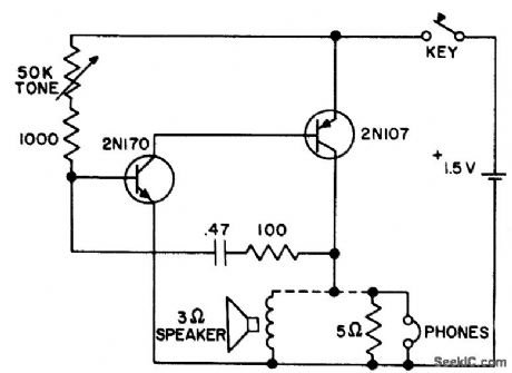
Requires only single flashlight cell and two transistors. - Transistor Manual, Seventh Edition, General Electric Co., 1964, p 378. (View)
View full Circuit Diagram | Comments | Reading(0)
30_MC_2N2188
Published:2009/7/19 21:21:00 Author:Jessie
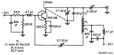
Delivers 23 mw over temperature range of -40 to +60℃. Typical collector efficiency is 30%.-Texas Instruments Inc., Transistor Circuit Design, McGrctw-Hill, N.Y., 1963, p 319. (View)
View full Circuit Diagram | Comments | Reading(713)
PREFERRED_SERIES_TRIGGERED_BLOCKING_OSCILLATOR
Published:2009/7/19 21:48:00 Author:Jessie
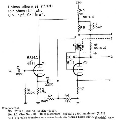
Responds to more slowly rising trigger than parallel-triggered version. Gathode follower V1 is included to provide required low driving impedance and minimize reaction of oscillator on trigger source. Designed for repetition rates up to 2,000 pps. Four terminals give choice of positive or negative output from positive input. Plate voltage is 300 V for 5814A and 150 V for 6111.-NBS, Handbook Preferred Circuits, Navy Aeronautical Electronic Equipment, Vol.I, Electron Tube Circuits, 1963, PC 49, p 49-2. (View)
View full Circuit Diagram | Comments | Reading(971)
| Pages:23/54 At 202122232425262728293031323334353637383940Under 20 |
Circuit Categories
power supply circuit
Amplifier Circuit
Basic Circuit
LED and Light Circuit
Sensor Circuit
Signal Processing
Electrical Equipment Circuit
Control Circuit
Remote Control Circuit
A/D-D/A Converter Circuit
Audio Circuit
Measuring and Test Circuit
Communication Circuit
Computer-Related Circuit
555 Circuit
Automotive Circuit
Repairing Circuit