
Oscillator Circuit
Index 25
TWO_FREQUENCY_COLPITTS_OSCILLATOR
Published:2009/7/10 2:49:00 Author:May
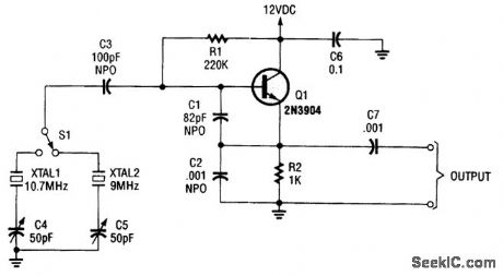
Using switched crystals, this oscillator is intended for receiver alignment purposes. (View)
View full Circuit Diagram | Comments | Reading(826)
CODE_PRACTICE_OSCILLATOR_I
Published:2009/7/10 2:49:00 Author:May
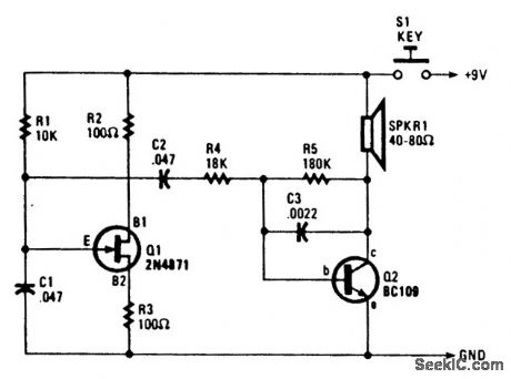
Q1, a unijunction transistor, generates a sawtooth of about 1.5 to 2 kHz, depending on C1 and R1. Q2 acts as a speaker driver. A 9-V battery is used, and the keying is done by keying the supply line. (View)
View full Circuit Diagram | Comments | Reading(974)
FET_PHASE_SHIFT_OSCILLATOR
Published:2009/7/19 22:18:00 Author:Jessie
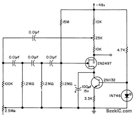
Frequency of four-mesh phase-shift oscillator can be varied several cycles around 10 cps, using 2.5-meg pot. Attenuation of four-mesh feedback network is 18.36.-L. J. Sevin, Jr., Field-Effect Transistors, McGraw-Hill, N.Y., 1965, p 111. (View)
View full Circuit Diagram | Comments | Reading(1403)
50_to_150_MHz_OSCILLATOR
Published:2009/7/10 2:48:00 Author:May

View full Circuit Diagram | Comments | Reading(826)
FEEDBACK_OSCILLATOR
Published:2009/7/19 22:17:00 Author:Jessie
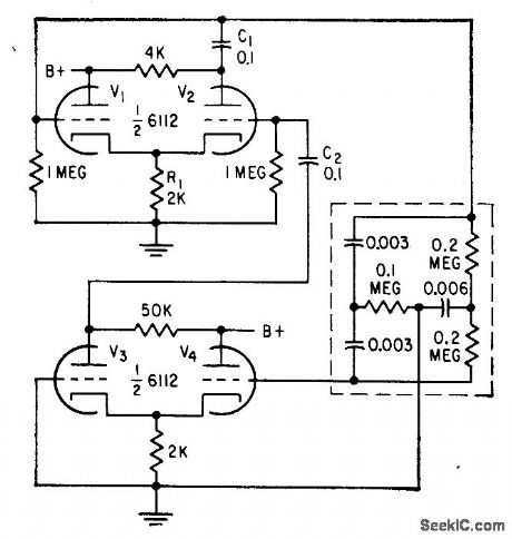
C1 provides positive feedback between amplifier V2 and cathode follower V1, causing oscillation at frequency and amplitude at which loop gain is unity. Twin-T network in negative feed-back loop maintains pure sine wave, free of harmonics. Variable-gain negative-feedback amplifier V3-V4 stabilizes frequency and amplitude at prescribed values.-Oscillator Patent is Granted, Electronics, 31;37, p 108. (View)
View full Circuit Diagram | Comments | Reading(842)
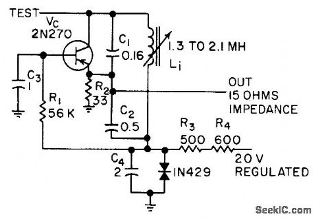
STABLE_VFO
Published:2009/7/10 2:45:00 Author:May
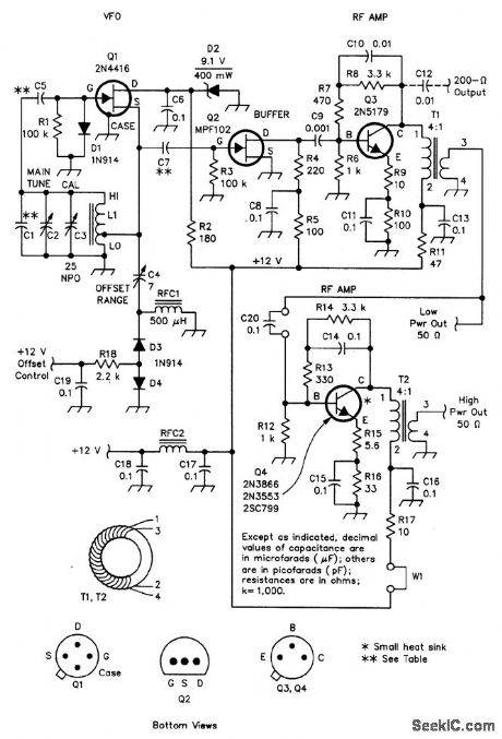

This VFO circuit covers from 2.13 to 2.58 MHz and is intended for use with an external mixer to heterodyne the signal to desired frequencies. Coil data is shown in the parts list. Two power outputlevels are available-a few hundred mW (0 to + 3 dbm) from Q3. Q4 is a class A amplifier for boosting the power to +22 dbm for driving a high-level mixer. The VFO can be operated on other frequencies, with suitable component charges (see the table). (View)
View full Circuit Diagram | Comments | Reading(1181)
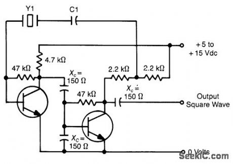
150_to_30_000_kHz_OSCILLATOR
Published:2009/7/10 2:45:00 Author:May
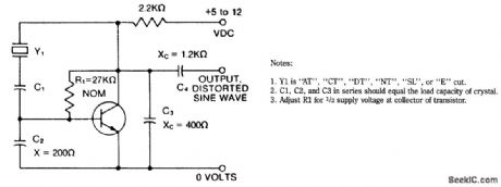
C1 capacitor in series with the crystal may be used to adjust the output frequency of the oscillator. The value can range between 20 pF and 0.01 μF, or it can be a trimmer capacitor.
X values are approximate and can vary for most circuits and frequencies; this is also true for resistance values. Adequate power supply decoupling is required; local decoupling capacitors near the oscillator are recommended. (View)
View full Circuit Diagram | Comments | Reading(908)
CASCADE_TUNNEL_DIODE
Published:2009/7/19 22:16:00 Author:Jessie
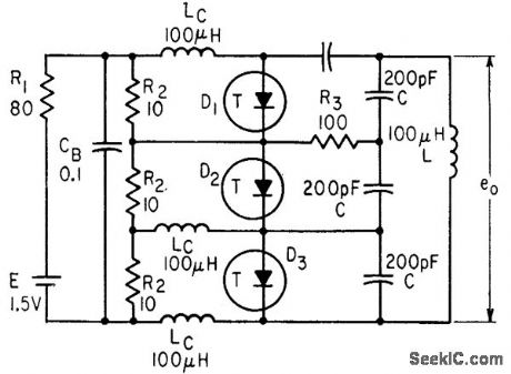
Voltage drops across resistors R2 serve as individual voltage sources in series for cascaded diodes that give three times sine-wave output voltage of single relaxation oscillator circuit.-Wen-Hsiung Ko, Designing Tunnel Diode Oscillators, Electronics, 34:6, p 68-72. (View)
View full Circuit Diagram | Comments | Reading(1005)
1_to_4_MHz_CMOS_OSCILLATOR
Published:2009/7/10 2:42:00 Author:May
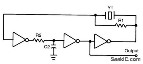
Notes:
1 1 MΩ<R1<5 MΩ2 Select R2 and C2 to prevent spunous frequency.3 ICs are 74C04 or equiwlent (View)
View full Circuit Diagram | Comments | Reading(628)
FET_VOLTAGE_CONTROLLED_OSCILLATOR
Published:2009/7/19 22:15:00 Author:Jessie
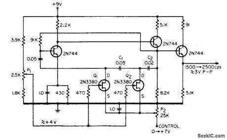
Produces excellent sine-wave output with good linearity over frequency range of 1,500 to 2,500 cps, for control voltage of 0to 7 V d-c. Circuit is resistance-controlled three-section phase-shift oscillator.-R. Selleck, Voltage-Controlled Oscillators, EEE, 13:3, p 47. (View)
View full Circuit Diagram | Comments | Reading(985)
FEEDBACK_LOOP_STABILIZES_A_F_OSCILLATOR_AMPLIFIER
Published:2009/7/19 22:14:00 Author:Jessie
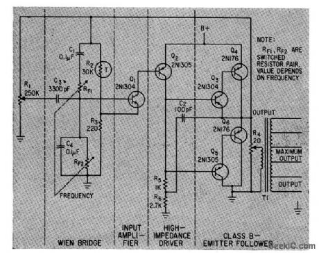
Wien bridge determines frequency of oscillator, which is combined with amplifier stages to give single oscillator stage having suffident output power to drive load directly. Thermistor R2 and resistor R3 provide negative feedback path around amplifier and oscillator, to make oscillator gain and frequency independent of load variations.-R. G. Fulks, Novel Feedback loop Stabilizes Audio Oscillator, Electronics, 36:5, p 42-43. (View)
View full Circuit Diagram | Comments | Reading(768)
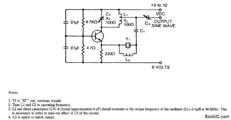
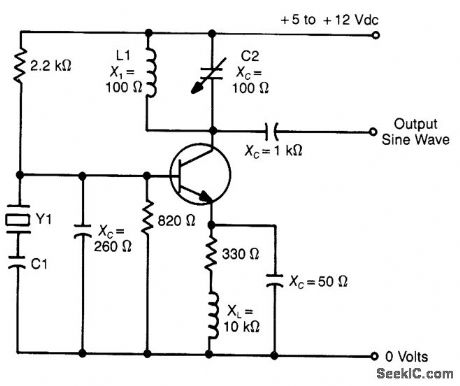
lO_to_80_MHz_OSCILLATOR
Published:2009/7/10 2:41:00 Author:May
Notes:1. Y1 is AT cut, fundamental, or overtone crystal.2. Tune L1 and C2 to operating frequency. (View)
View full Circuit Diagram | Comments | Reading(743)
QUADRATURE_OUTPUTS_OSCILLATOR
Published:2009/7/10 2:39:00 Author:May
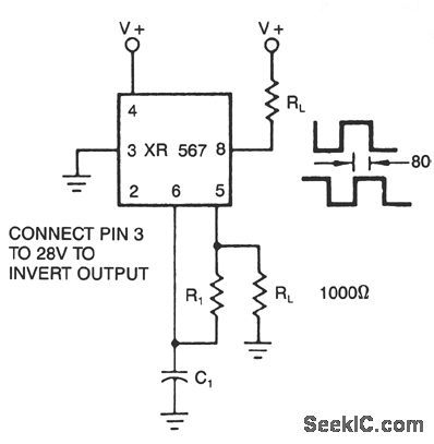
The XR-567 functions as a precision oscillator with two separate square-wave outputs at pins 5 and 8, that are at nearly quadrature phase with each othen. Because of the internal biasing arrangement, the actual phase shift between the two outputs is typically 80%. (View)
View full Circuit Diagram | Comments | Reading(951)
HIGH_CURRENT_OSCILLATOR
Published:2009/7/10 2:38:00 Author:May
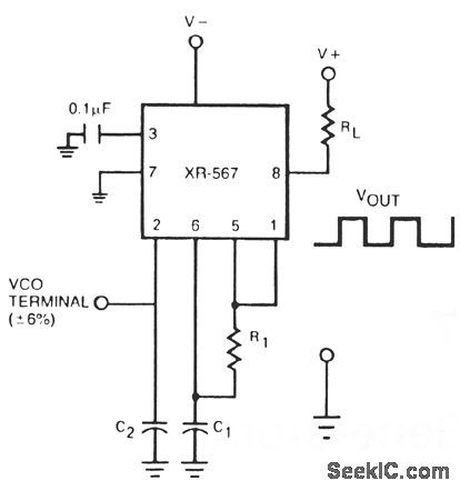
The oscillator output of the XR-567 can be amplified using the output amplifier and high-current logic output available at pin 8. In this manner, the circuit can switch 100-mA load currents without sacrificing oscillator stability. The oscillator frequency can be modulated over ±6% in frequency by applying a control voltage of pin 2. (View)
View full Circuit Diagram | Comments | Reading(2448)
20_MC_POWER_OSCILLATOR
Published:2009/7/19 22:12:00 Author:Jessie
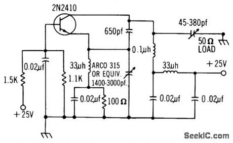
Colpitts-type common-base circuit gives power output of 500 mw to 50-ohm load, while dissipating 750 mw. –Texas Instruments Inc., “Solid-State Communications,” McGraw-Hill, N. Y., 1966, p 300. (View)
View full Circuit Diagram | Comments | Reading(876)
10_to_150_KHz_OSCILLATOR
Published:2009/7/10 2:38:00 Author:May

Note:Y1 is H , NT , E cut (View)
View full Circuit Diagram | Comments | Reading(798)
10_MC_CRYSTAL
Published:2009/7/19 22:11:00 Author:Jessie
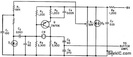
Collector voltage of transistor is kept low and is stabilized by zener diode D1 in microminiature oscillator using crystal in 10-Mc fundamental mode. Voltage-sensitive capacitor D2 and R7 serve for fine frequency adjustmets.-M. Lysobey, Microminiature Crystal Oscillator Using Wafer Modules, Electronics, 35:15, p 60-61. (View)
View full Circuit Diagram | Comments | Reading(691)
STABLE_SUBCARRIER_OSCILLATOR
Published:2009/7/19 22:11:00 Author:Jessie
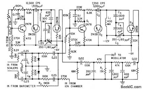
Two Colpitts oscillators, designed for 7,350 cps and 12,300 cps, are used with reactance-type frequency modulation. Input stage of each oscilllator is temperature-stabilized by d-c feedback.-D. Enemark, Balloon-Borne Circuits Sort High-Altitude Cosmic Rays, Electronics, 32:35, p 52:,55.
(View)
View full Circuit Diagram | Comments | Reading(794)
330_MHz_CRYSTAL_OSCILLATOR
Published:2009/7/10 2:37:00 Author:May
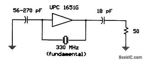
A μPC 16516G IC operates in the fundamental mode with an experimental crystal at 330 MHz. The 56-to-270 pF capacitor is not critical; about + 1-dBm RF output is available. (View)
View full Circuit Diagram | Comments | Reading(660)
STABLE_10_KC_COLPITTS
Published:2009/7/19 22:10:00 Author:Jessie
Provides constant-amplitude carrier for data reduction system, at 0.5 V rms with amplitude stability of 0.l% and frequency drift below 0.25% for temperature range of 30 to 50℃.-L. H. Dulberger, Transistor Oscillator Supplies Stable Signal, Electronics, 31:5, p 43. (View)
View full Circuit Diagram | Comments | Reading(777)
| Pages:25/54 At 202122232425262728293031323334353637383940Under 20 |
Circuit Categories
power supply circuit
Amplifier Circuit
Basic Circuit
LED and Light Circuit
Sensor Circuit
Signal Processing
Electrical Equipment Circuit
Control Circuit
Remote Control Circuit
A/D-D/A Converter Circuit
Audio Circuit
Measuring and Test Circuit
Communication Circuit
Computer-Related Circuit
555 Circuit
Automotive Circuit
Repairing Circuit