
Oscillator Circuit
Index 38
7_MHz
Published:2009/7/2 9:12:00 Author:May
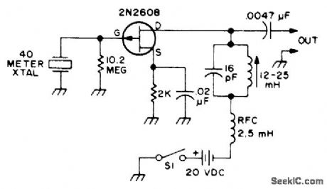
Uses single Siliconix 2N2608 FET. Keep leads short. Coil can be air-wound or permeability-tuned. If tuning capacitor is variable, coil value can be fixed. RF output level depends on circuit voltages and on activity of crystal used.-Q & A, 73 Magazine, April 1977, p 165. (View)
View full Circuit Diagram | Comments | Reading(1027)
MODULATED_CRYSTAL
Published:2009/7/2 9:11:00 Author:May
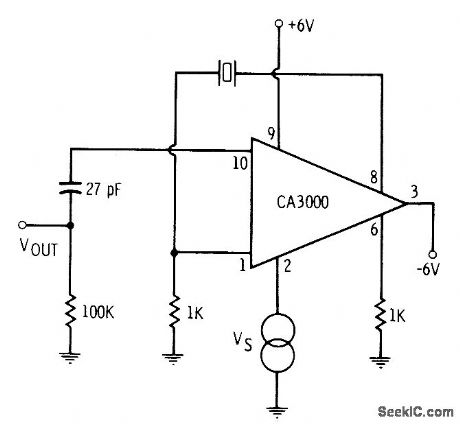
CA3000 differential amplifier is operated as efficient crystal-controlled oscillator. Output frequency depends on crystal. If desired, RF output can be modulated with low-frequency tone applied between pin 2 and ground.-E. M. Noll, Linear IC Principles, Experiments, and Proiects, Howard W. Sams, Indianapolis, IN, 1974, p 91. (View)
View full Circuit Diagram | Comments | Reading(1042)
100_kHz_CPYSTAL_FET_RELAXATION
Published:2009/7/2 9:08:00 Author:May
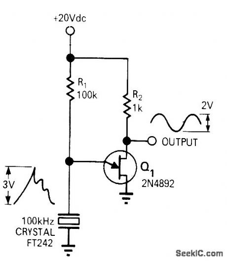
Adding crystal in frequency-determining circuit improves frequency stabrlity of UJT relaxation oscillator. With charging capacitor replaced by 100-kHz quartz crystal, measured output frequency was 99.925 kHz. -R. D. Clement and R. L. Starliper, Crystal-Controlled Relaxation Oscillator, EDN|EEE Magazine, Oct. 15, 1971, p 62 and 64. (View)
View full Circuit Diagram | Comments | Reading(1038)
CRYSTAL_COLPlTTS
Published:2009/7/2 9:05:00 Author:May
Circuit is ideal for low-frequency crystal oscillators because JFET circuit loading does not vary with temperature. Output frequency is determined by threshold used.- FET Databook, National Semiconductor, Santa Clara, CA, 1977, p 6-26-6-36. (View)
View full Circuit Diagram | Comments | Reading(1137)
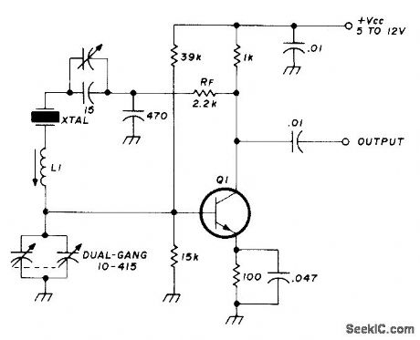
8_MHz_±_5_kHz
Published:2009/7/2 9:05:00 Author:May
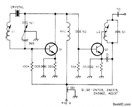
Tuning two-gang 365-pF variable capacitor through its range provides frequency change up to 5 kHz in output of 8-MHz crystal oscillator. L1 is 16-24 μH Miller 4507, and L2 is 40 turns No.36 tapped at 13 turns, on 1/4-inch slug-tuned form.-Circuits, 73 Magazine, Jan. 1974, p 128. (View)
View full Circuit Diagram | Comments | Reading(1171)
2255_2455_kHz_LOCAL_OSCILLATOR
Published:2009/7/2 9:04:00 Author:May
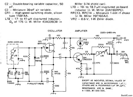
Used in 1.8-2 MHz communication receiver having wide dynamic range. Oscillator has good stability, with circuit noise at least 90 dB below fundamental output. Amplifier Q14 provides required +7 dBm for in jection into balanced mixer of receiver. Two-part article gives all other circuits of receiver.-D. DeMaw, His Eminence-the Receiver, QST, Part 1-June 1976, p 27-30 (Part 2-July 1976, p 14-17). (View)
View full Circuit Diagram | Comments | Reading(985)
5_MHz_±_250_kHz
Published:2009/7/2 9:03:00 Author:May
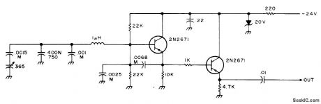
Simple and stable circuit using PNP transistors has tuning range of about 250 kHz in any segment of 5-9 MHz range, depending on how oscillator coil is set. Wind coil on ceramic form or use air-wound coil. Capacitors marked M should be mica for stability. Tuning capacitor is 365 pF,from AM radio, 400/N750 temperature-compensating capacitor can be replaced by 400-pF mica unless VFO is used in mobile application.-An Accessory VFO-the Easy Way, 73 Magazine, Aug. 1975, p 103 and 106-108. (View)
View full Circuit Diagram | Comments | Reading(789)
VARIABLE_CRYSTAL
Published:2009/7/2 9:02:00 Author:May
Maximum frequency shift is almost 10 kHz at 5 MHz. Use crystal made especially for variable operation. Frequency stability is good even at extremes of shift. Use 5-20 μH for L1 with crystals from 6-15 MHz, and 20-50 μH for 3-6 MHz. Q1 is 2N3563, 2N3564, 2N5770, BC107, BC547, BF115, BF180, SE1010, or equivalent.-R. Harrison, Sulvey of Crystal Oscillators, Ham Radio, March 1976, p 10-22. (View)
View full Circuit Diagram | Comments | Reading(2435)
QUADRATURE__OSCILLATOR
Published:2009/7/2 7:45:00 Author:May
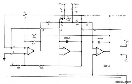
Addition of diode limiter and positive-feedback resistor to UAF41 universal active filtrer gives precision quadrature oseillator.-Y. J. Wong, Design a Low Cost, Low-Distortion, Precision Sine-Wave Oscillator,EDN Magazzine,Sept20, 1978,p 107-113. (View)
View full Circuit Diagram | Comments | Reading(1068)
8O0_kHz_OSCILLATOR
Published:2009/7/2 7:28:00 Author:May
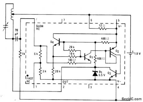
National LM3909 IC operating from single 1.5-V cell is used with standard AM radio ferrite antenna coil having tap 4070 of turns from one end, with standard 365 pF tuning capacitor across coil. Developed for demonstrating versatility of this low-voltage IC.- Linear Applications, Vo1. 2. National Semiconductor, Santa Clara, CA, 1976, AN-154, p8. (View)
View full Circuit Diagram | Comments | Reading(766)
SWITCHED_CRYSTALS
Published:2009/7/2 7:28:00 Author:May
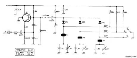
High stability is combined with multichannel selection by diode switching of crystals in range of 2-20 MHz, used in series-resonant mode. L1 is about 30 μH at 2 MHz and 1 μH at 20 MHz. Q1 is 2N708, HEP50, BC108, or similar NPN RF type Diodes are switching types such as BAY67.-U. Rohde, Stable Crystal Oscillators, Ham Radio, June 1975, p 34-37. (View)
View full Circuit Diagram | Comments | Reading(1307)
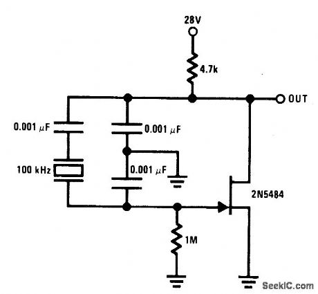
JFET_PIERCE_CRYSTAL
Published:2009/7/2 7:27:00 Author:May
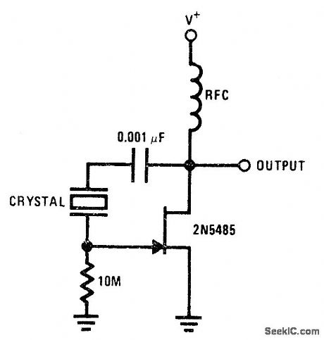
Basic JFET oscillatorcircuit permits use of wide frequency range of crystals. High Q is maintained because JFET gate does not load crystal, thereby ensuring good frequency stability.- FET Databook, National Semiconductor, Santa Clara, CA, 1977, p 6-26-6-36. (View)
View full Circuit Diagram | Comments | Reading(1000)
3955_4455_MHz_VFO
Published:2009/7/2 7:12:00 Author:May
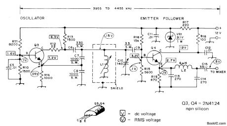
Basic Colpitts LC oscillator designed for 80-meter receivel wiith 455-kHz IF uses zener in supply line to minimize frequncy drift. Emitter-follower buffer contributes to stability by isolating oscillator frommlxer Low-pass filter C13-L2-C14 attenuates harmonic currents developed in Q3 and Q4. L1 is Miller 4503 1.7-2.7 μH variable inductor. L2 is 48 turns No.30 enamel closewound on 1/4-inch wood dowel or polystyrene rod. Main tuning capacitor C10 can be 365-pF unit with six of rear rotor plates removed.-D. DeMaw and L. McCoy, Learning to Work with Semiconductors, QST, June 1974, p 18-22 and 72. (View)
View full Circuit Diagram | Comments | Reading(2269)
1O_2O_MHz_CRYSTAL
Published:2009/7/2 7:11:00 Author:May
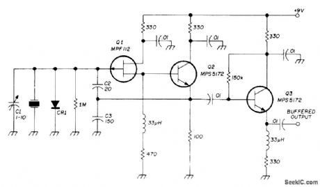
Modification of basic Colpitts crystal oscillator has excellent load capacitance correlationand temperature stability. Crystal will oscillate very close to its series resonant point. Component values are optimized for 10-20 MHz. Emitter-follower Q2 provides power gain for feedback energy and gives high crystal activity without changing phase angle of signal. Output buffer Q3 prevents loading of oscillator. Q1 is low-cost Motorola JFET, but practically any other JFET will work CR1 is 1N914 or 1N4148.-D. L. Stoner, High-Stability Crystal Oscillator, Ham Radio, Oct. 1974, p 36-39. (View)
View full Circuit Diagram | Comments | Reading(1672)
1_20_MHz_FUNDAMENTAL_CRYSTAL
Published:2009/7/2 7:02:00 Author:May
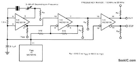
Oscillator requires no resonant tank circuit for frequencies below 20 MHz. Use of noninverting output makes oscillator section of Motorola MC10116 IC function simply as amplifier. Second section is connected as Schmitt trigger to improve signal waveform. Third section is buffer providing complementary outputs.-B. Blood, IC Crystal Controlled Oscillators, Motorola, Phoenix, AZ, 1977, AN-417B, p 4. (View)
View full Circuit Diagram | Comments | Reading(886)
METAL_FOIL_SPOTWELDING_CONTROL
Published:2009/7/24 2:15:00 Author:Jessie
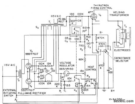
Permits precise control of high-energy capacitor discharge used in welding extremely thin and highly conductive foils or fine wires. Heat control provides range of 650 to 1,500 v for level at which energy is stored, and selector switch gives choice of 50, 100, and 200 mfd for storage capacitor.-J. Markus, Handbook of Electronic Control Circuits, McGraw-Hill, New York, 1959, p 321. (View)
View full Circuit Diagram | Comments | Reading(1371)
DATA_COUPLER_WITH_ISOLATION
Published:2009/7/2 2:04:00 Author:May

Length of fiber or polystyrene rod determines amount of voltage isolation provided between digital or analog signal input and Fairchild FPT 100 photodetector driving Optical Electronics 9720 opamp having 100-mA output for driving cables, relays, or loudspeakers. LED can be Monsanto MV50 handling up to 200 mA. Output of opamp is zero for no light. Pulse-duration modulation should be used for transmission of analog data.- High Voltage Optically Isolated Data Coupler, Optical Electronics, Tucson, AZ,Application Tip 10266. (View)
View full Circuit Diagram | Comments | Reading(813)
50_MHz_CRYSTAL
Published:2009/7/2 1:07:00 Author:May
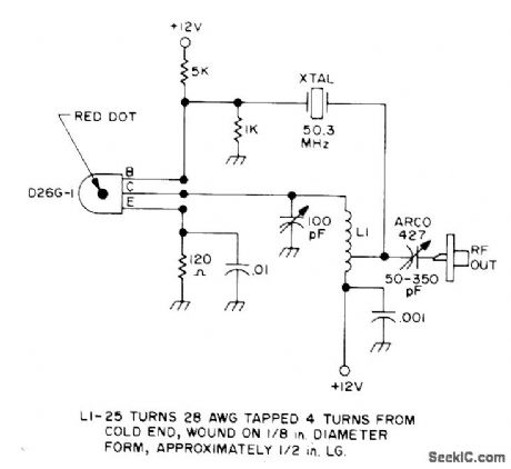
Uses microtransistor as oscillator handling 100-mW input power and giving 40-50% efficiency. Article covers construction with microcomponents and gives other microtransistor circuits for low-power amateur radio use and possible bugging applications.-B. Hoisington, Introduction to Microtransistors, 73 Magazine, Oct. 1974, p 24-30. (View)
View full Circuit Diagram | Comments | Reading(833)
279611_kHz_CRYSTAL
Published:2009/7/2 1:05:00 Author:May
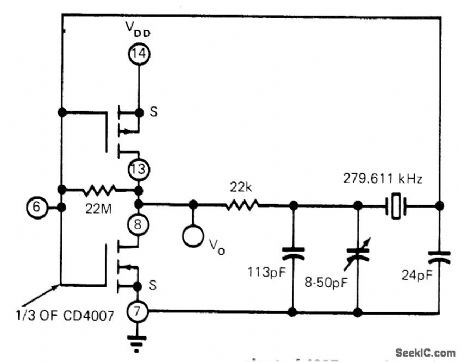
DT-cut quartz crystal operating in CMOS inverter pair circuit serves as efficienttiming circuit. Supply voltage can be from 5 to 15 V. With TA5987 Low-voltage equivalent of 4007, supply can be 2.5 to 5 V. Stability is 4.3 PPM, not including temperature variations.-B. Furlow, CMOS Gates in Linear Applications: The Results Are Surprisingly Good, EDN Magazine, March 5, 1973, p 42-48. (View)
View full Circuit Diagram | Comments | Reading(795)
5_MHz_LOW_NOISE_CRYSTAL
Published:2009/7/2 1:03:00 Author:May
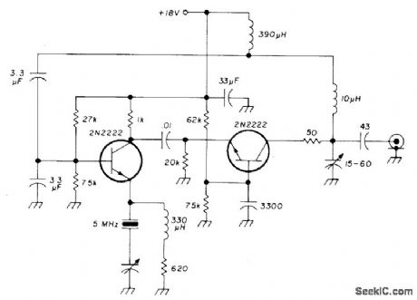
Extremely low-noise series-mode crystal oscillatoris designedfor use in high-quality communication receivers. Eitherfundamental or overtone crystals can be used.-U. L. Rohde, Effects of Noise in Receiving Systems, Ham Radio, Nov. 1977, p 34-41. (View)
View full Circuit Diagram | Comments | Reading(898)
| Pages:38/54 At 202122232425262728293031323334353637383940Under 20 |
Circuit Categories
power supply circuit
Amplifier Circuit
Basic Circuit
LED and Light Circuit
Sensor Circuit
Signal Processing
Electrical Equipment Circuit
Control Circuit
Remote Control Circuit
A/D-D/A Converter Circuit
Audio Circuit
Measuring and Test Circuit
Communication Circuit
Computer-Related Circuit
555 Circuit
Automotive Circuit
Repairing Circuit