
Oscillator Circuit
Index 26
SIMPLE_WIEN_BRIDGE_OSCILLATOR
Published:2009/7/10 2:35:00 Author:May
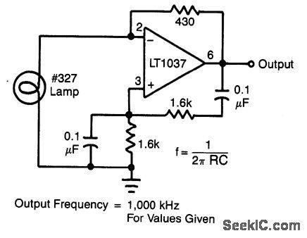
In this circuit, the Wien-bridge network provides phase shift, and the lamp regulates the amplitude of the oscillations. The smooth, limiting nature of the lamp's operation, in combination with its simplicity, gives good results. Harmonic distortion is below 0.3% (View)
View full Circuit Diagram | Comments | Reading(1887)
PREFERRED_PARALLEL_TRIGGERED_BLOCKING_OSCILLATOR_BELOW_2000_PPS
Published:2009/7/19 22:09:00 Author:Jessie
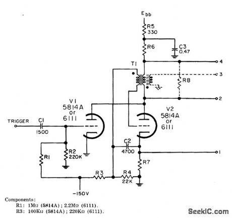
Produces synchronizing impulses between 0.2 and 7 microsec wide at rates of 200 to 2,000 pps. One triode section is used as trigger amplifier to prevent triode blocking oscillator from reacting on trigger source. R6 and R7 are 100 ohms for 5814A and 150 ohms for 6111. R8 should be maximum that will just suppress ringing. Requires positive input trigger and gives choice of output polarities at the four output terminals.-NBS, Handbook Preferred Circuits Navy Aeronautical Electronic Equipment, Vol. I, Electron Tube Circuits, 1963, PC 46, p 46-2. (View)
View full Circuit Diagram | Comments | Reading(730)
ANEMOVANE_AUDIO_OSCILLATOR
Published:2009/7/19 22:07:00 Author:Jessie
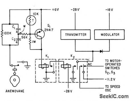
Used for telemetering wind velocity. Cam switch closes for each mile of wind that passes the anemometer cups, applying voltage to C1 and C2 in series and making Q1 conduct and pull in K1. This energizes velocity audio oscillator of telemetry system.-R. Beaulieu and G. Neal, Wind Velocity Telemetering System, Electronics, 33:29, p 68-70. (View)
View full Circuit Diagram | Comments | Reading(808)
VOLTAGE_CONTROLLED_CRYSTAL_OSCILLATOR
Published:2009/7/10 2:30:00 Author:May
View full Circuit Diagram | Comments | Reading(0)
60_MC_COMMON_BASE_1_
Published:2009/7/19 22:07:00 Author:Jessie
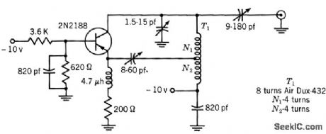
Delivers 10 mw to 50-ohm load at 25℃. Collector efficiency is 10%.-Texas Instruments Inc., Solid-State Communications, McGraw-Hill, N.Y., 1966 p 239. (View)
View full Circuit Diagram | Comments | Reading(780)
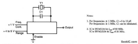
100_MHz_OVERTONE_OSCILLATOR
Published:2009/7/10 2:28:00 Author:May
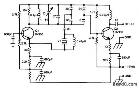
This oscillator circuit uses a 5th overtone crystal in the 85-to-106 MHz range. Y1 ii the crystal. The circuit was originally used to frequency control a microwave oscillator. (View)
View full Circuit Diagram | Comments | Reading(1478)
OSCILLATOR_D_E_T_E_C_T_O_R
Published:2009/7/19 22:06:00 Author:Jessie

Capacitor microphones form part of grid tank circuit of 6-Mc tuned-plate tuned-grid r-f oscillator that also detects 6.5-cps modulation by class-C operation during oscillation. Used in infrared analyzer for detecting leaks in automobile airsuspension systems.-P. G. Balko, Infrared Finds Auto Suspension Leaks, Electronics, 31:49, p 82-85. (View)
View full Circuit Diagram | Comments | Reading(705)
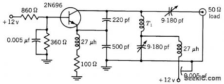
60_MC_COMMON_BASE
Published:2009/7/19 22:04:00 Author:Jessie
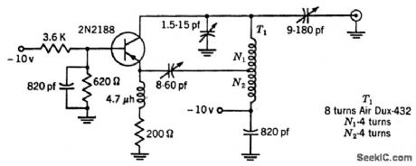
Delivers 10 mw to 50-ohm load at 25℃. Collector efficiency is 10%.-Texas Instruments Inc., Transistor Circuit Design, McGraw-Hill, N.Y., 1963, p 320. (View)
View full Circuit Diagram | Comments | Reading(743)
5_CPS_TO_300_KC
Published:2009/7/19 22:03:00 Author:Jessie
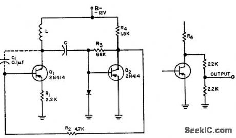
Overcomes low-frequency problems of wide-range oscillators by using tank both for controlling frequency and coupling signal to next stage. Frequency is stable over wide variations in d-c voltage and temperature, yet circuit is inexpensive. Alternative output coupling shown is useful for driving varying loads.-J. Freeman, Low-Frequency C-Coupled Oscillator, EEE, 11:7, p 27-28. (View)
View full Circuit Diagram | Comments | Reading(696)
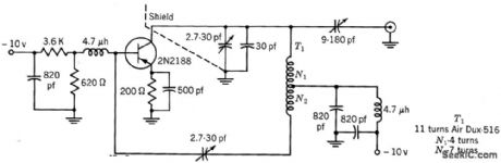
VOLTAGE_CONTROLLED_BUTLER_OSCILLATOR_
Published:2009/7/19 22:02:00 Author:Jessie

Provides 70% frequency deviation. When tuned to 2 Mc, frequency deviation is -205 kc at 0 V control input and +1,289 kc at 20 V, though frequency deviation is not linearly proportional in lower half of voltage range. -C. F. Turner, Wide-Range, Voltage-Controlled Oscillator, EEE, 10:10, p 31. (View)
View full Circuit Diagram | Comments | Reading(1406)
30_MC_WIDE_TEMPERATURE_RANGE
Published:2009/7/19 21:57:00 Author:Jessie
Operates over range of -40 to +60℃. Typical power output is 23 mw at lowest temperature and 20 mw at highest. Collector efficiency is 30%.-Texas Instruments Inc., Solid-State Communications, McGraw-Hill, N.Y., 1966, p 239. (View)
View full Circuit Diagram | Comments | Reading(726)
27255_MC_TUNNEL_DIODE_CRYSTAL_OSCILLATOR
Published:2009/7/19 21:56:00 Author:Jessie
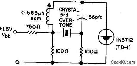
Operates within tolerance of quartz crystal from -55 to + 85℃ and bias range of 110 to 150 mv for Citizens Band service. - Transistor Manual, Seventh Edition, General Electric Co., 1964, p 353. (View)
View full Circuit Diagram | Comments | Reading(680)
VOLTAGE_CONTROLLED_VFO
Published:2009/7/19 21:55:00 Author:Jessie
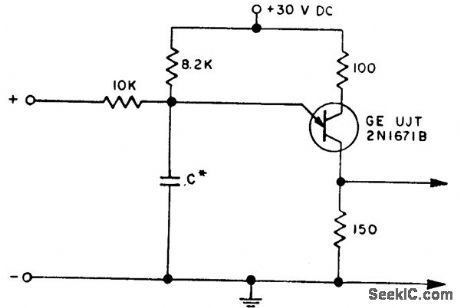
Adding 10K resistor to basic ujt oscillator gives voltage-controlled variable-frequency oscillator. With 0.68 mfd for C, d-c input voltage range of 0 to 30 V gives 670 to 4,550 pps. With 0.2 mfd for C, same input range gives 220 to 1,400 pps. Not intended for use where linearity is important.-B. Strunk, Voltage-Controlled Variable-Frequency Oscillator, EEE, 10:12, p 28-30. (View)
View full Circuit Diagram | Comments | Reading(758)
MULTIPLE_FEEDBACK_R_C_OSCILLATOR
Published:2009/7/19 21:54:00 Author:Jessie
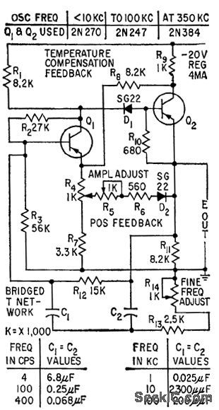
Gives excellent amplitude stability and low distortion. Uses vibration and shockproof version of Sulzer bridged-T configuration to provide single-frequency operation in 4-cps to 350-kc range.-L. H. Dulberger, Improved R-C Oscillator, Electronics, 32:10, p 62. (View)
View full Circuit Diagram | Comments | Reading(713)
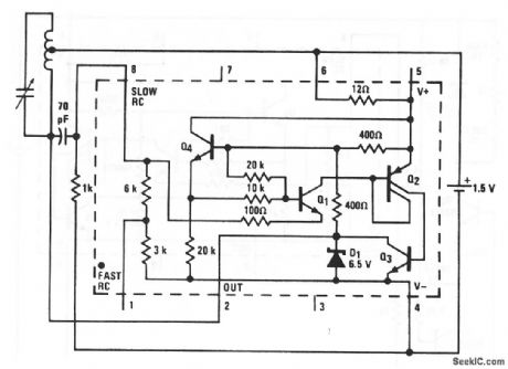
SYNCHRONIZED_OSCILLATOR
Published:2009/7/19 22:30:00 Author:Jessie
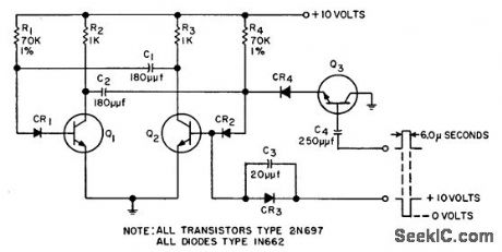
Astable mvbr Q1-Q2 operating at68.4 kc is synchronized by 400-cps signal having 6-microsec pulse width. Frequency stability can be one part in 4,000 if film resistors and other temperature-stable components are used. Synchronizing signal is variable, of the order of 1/170 of oscillator frequency but with no integral relationship between the signals.-G. Silver-man. A Synchronized Oscillator Circuit, EEE, 10:7, p 29-30. (View)
View full Circuit Diagram | Comments | Reading(0)
7413_MC_CRYSTAL_REPLACES_LOST_MICRO_WAVE_CARRIER
Published:2009/7/19 22:33:00 Author:Jessie
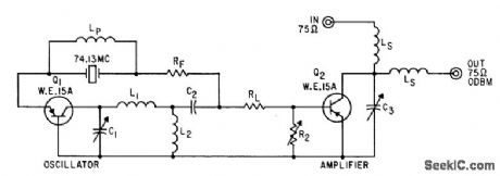
To prevent noise interference during signal losses due to fading, carriet resupplies oscillator, and amplifier replaces lost carrier, within 0.1 millisec. Q1 and Q2 are switched from cutoff when carrier is needed. Resistor RF in series with crystal lowers its Q to insure rapid starting. -Microwave Relay Designing with Traveling-Wave Tubes, Electronics, 35:3, p 40-43. (View)
View full Circuit Diagram | Comments | Reading(845)
10_KC_SINGLE_TRANSISTOR_COLPITTS
Published:2009/7/19 22:32:00 Author:Jessie
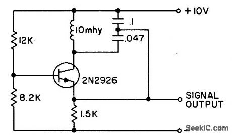
Total temperature drift rate is only 0.035%/℃, determined by coil core material. For higher frequency stability, frequency-determining network should be buffered from amplifier. - Transistor Manual, Seventh Edition, General Electric Co., 1964, p 210. (View)
View full Circuit Diagram | Comments | Reading(2144)
24_MC_CLAPP_1
Published:2009/7/19 23:20:00 Author:Jessie
Delivers 300 mw into 50-ohm load. Typical collector efficiency is 35%. -Texas Instruments Inc., Solid-State Communications, McGraw-Hill, N.Y., 1966, p 239. (View)
View full Circuit Diagram | Comments | Reading(682)
RF_oscillator_
Published:2009/7/19 23:20:00 Author:Jessie

This circuit uses the LM3909 as a low-power RF oscillator (chapter 5). The tuned circuit is a standard AM-radio ferrite antenna coil (loopstick) with a tap 40% of the turns up from one end. The tuning capacitor is a standard 360-pF AM-radio tuning capacitor The high-frequency limit is about 800 kHz. (View)
View full Circuit Diagram | Comments | Reading(1240)
DELAY_LINE_OSCILLATOR
Published:2009/7/19 23:19:00 Author:Jessie
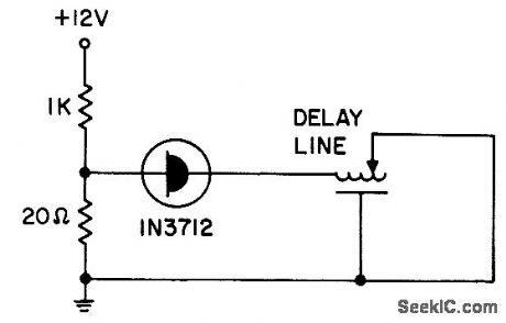
Tunnel-diode oscillator with General Radio 314-586 delay line produces square-wave output in range of 0.5 to 20 Mc.- Transistor Manual, Seventh Edition, General Electric Co., 1964, p 352. (View)
View full Circuit Diagram | Comments | Reading(1543)
| Pages:26/54 At 202122232425262728293031323334353637383940Under 20 |
Circuit Categories
power supply circuit
Amplifier Circuit
Basic Circuit
LED and Light Circuit
Sensor Circuit
Signal Processing
Electrical Equipment Circuit
Control Circuit
Remote Control Circuit
A/D-D/A Converter Circuit
Audio Circuit
Measuring and Test Circuit
Communication Circuit
Computer-Related Circuit
555 Circuit
Automotive Circuit
Repairing Circuit