
Oscillator Circuit
Index 27
PREFERRED_2000_83000_PPS_BLOCKING_OSCILLATOR
Published:2009/7/19 23:18:00 Author:Jessie
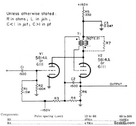
Parallel-triggered circuit responds to trigger pulses separated by only few microsec, as required for distance-mark generators and pulse coding circuits. Input is positive, with minimum of 15 V, and output is positive. R6 is 220 ohms. R7 is maximum that will just suppress ringing.-NBS, Handbook Preferred Circuits Navy Aeronautical Electronic Equipment, Vol. I, Electron Tube Circuits, 1963, PC 47, p 47-2. (View)
View full Circuit Diagram | Comments | Reading(778)
200_400_Mc_VARICAP_TUNED_OSCILLATOR_
Published:2009/7/19 23:15:00 Author:Jessie
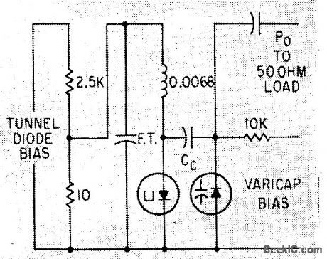
Tuning range is achieved by adjusting Voricap bias voltage from 0.4 to 60 V.-E. Gottlieb and J. Giorgis, Tunnel Diodes-Using Them as Sinusoidal Generators, Electronics, 36:24, p 36-42. (View)
View full Circuit Diagram | Comments | Reading(717)
ELECTRIC_TUNING_FOR_600_to_1200_MC
Published:2009/7/19 23:27:00 Author:Jessie
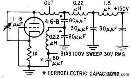
Lumped-constant technique is used with voltage-tunable ferroelectric capacitors to provide 10 mw into 50 ohms.-T. W. Buller, Jr., Ferroelectrics Tune Electronic circuits, Electronics, 32;3, p 52-55. (View)
View full Circuit Diagram | Comments | Reading(722)
SIMPLE_TRANSISTOR_OSCILLATOR
Published:2009/7/19 23:26:00 Author:Jessie
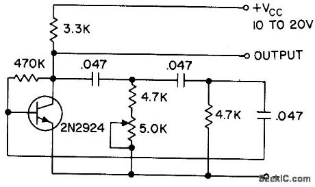
Current gain is stabilized against transistor variation. Can be used over collector voltage range of 2 to 24 V. Oscillation occurs at frequency at which there is 360° total phase shift, 180° of which is furnished by grounded-emitter amplifier and 180° by high-pass network. 5K pot adjusts frequency from about 200 to 400 cps.- Tansistor Manual, Seventh Edition, General Electric Co., 1964, p 206. (View)
View full Circuit Diagram | Comments | Reading(1196)
CHATTER_JAMMER
Published:2009/7/19 23:14:00 Author:Jessie
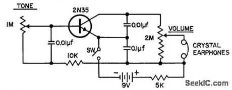
Can be used to create pleasing tone at level that drowns out ambient noises, to permit concentration on problem while others are talking in vicinity.-J. Leeb, A Chatter Jammer Circuit, EEE, 10:11, p 31. (View)
View full Circuit Diagram | Comments | Reading(796)
TONE_BURST_OSCILLATOR
Published:2009/7/19 23:12:00 Author:Jessie
Consists of variable-frequency magnetically coupled mvbr, with two magnetic cores driven by battery-powered transistors. Injection of current or voltage from solar cell or other transducer affects mvbr reset, to give frequency change over range of 5 to 15 kc.-R. W. Rochelle, Cyclops Cores Simplify Earth-Satellite Circuits, Electronics, 31:9, 56-63. (View)
View full Circuit Diagram | Comments | Reading(810)
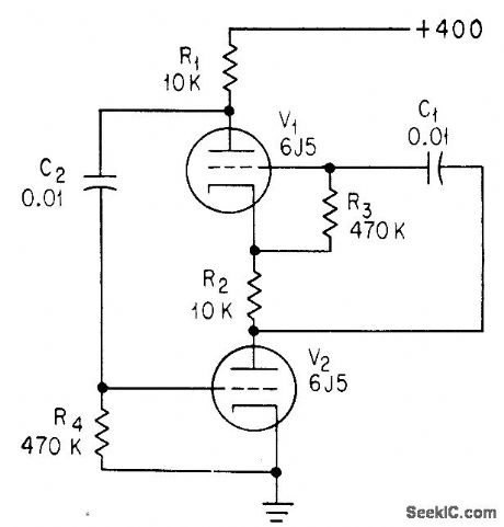
STABLE_OSCILLATOR
Published:2009/7/19 23:09:00 Author:Jessie
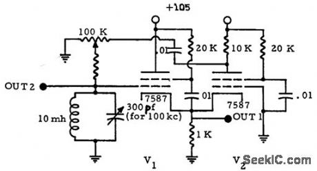
Excellent frequency and amplitude stability is accomplished by eliminating all grid current in tank circuit and by isolating tank from driving tube by means of resistive degeneration. If very pure sine wove is required, grid of V1 should be coupled to high-impedance load that is equivalent constant resistance, because either reacyive or variable loads will impair stability.-J. C. Davis, Stable Oscillator Circuit, EEE, 11:2, p 26. (View)
View full Circuit Diagram | Comments | Reading(1009)
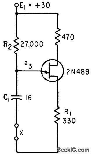
FOUR_LAYER_DIODE_OSCILLATOR
Published:2009/7/19 23:07:00 Author:Jessie
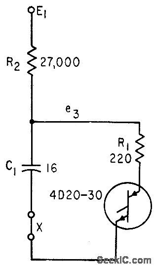
If circuit is broken at X, discharge current of C1 can be used to shut off transistor stage.-A. G. Lloyd, Overload Protection for Transistor Voltage Regulators, Electronics, 33:52, p 56-59. (View)
View full Circuit Diagram | Comments | Reading(812)
THREE_STAGE_VARIABLE_FREQUENCY_CRYSTAL_OSCILLATOR
Published:2009/7/19 23:03:00 Author:Jessie
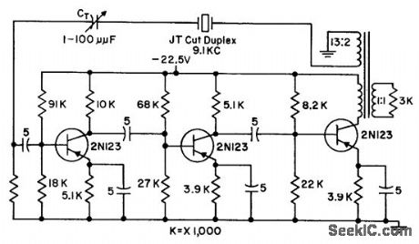
Provides loop transmission of 1, under maximum frequency pulloff of 5 cps from 9.1-kc crystal frequency, and has net phase shift around loop of 360°with crystal in circuit. Third stage provides extra circuit gain needed for larger power output or larger frequency deviations off resonance. Transformer provides phase reversal and reflects desired a-c load, to limit output swing of transistor.-G. A. Gedney and G. M. Davidson, Crystal Oscillator has Variable Frequency, Electronics, 31:7, p 118-119. (View)
View full Circuit Diagram | Comments | Reading(964)
MEASURING_OSCILLATOR_STABILITY
Published:2009/7/19 23:02:00 Author:Jessie
Circuit is used as 90.3125-Mc reference oscillator in system for measuring short-term stability of 45-Mc stalo (stable local oscillator) of airborne radar under high vibration. Tape transformer in collector circuit of transistor controls crystal drive.-J. Coolican, How to Measure STALO Short-Term Stability Under Vibration, EEE, 13:5, p 96-98. (View)
View full Circuit Diagram | Comments | Reading(995)
VOLTAGE_CONTROLLED_23_MC_OSCILLATOR_AND_MODULATOR
Published:2009/7/19 23:01:00 Author:Jessie
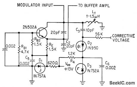
Input signal voltage to transistor changes capacitance of tank circuit, to make oscillator frequency vary with input signal voltage. Variable-capacitance diode requires fewer parts than transistor modulator. Zener diodes provide constant bias for variable-capacitance diode D2.-F. L. Carroll, How to Achieve Stability in Space Telemetry, Electronics, 37:4, p 32-35. (View)
View full Circuit Diagram | Comments | Reading(747)
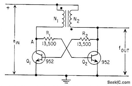
FREE_RUNNING_CASCODE_OSCILLATOR
Published:2009/7/19 22:59:00 Author:Jessie
Omission of voltage-divider capacitors from cascode multivibrator gives sine-wave oscillator if loop gain is equal to unity.-C. Sing, Advantages of Free-Running Cascode Multivibrators, Electronics, 37:5, p 28-29. (View)
View full Circuit Diagram | Comments | Reading(739)
100_KC_MAGNETOSTRICTIVE_ROD_CONTROL_
Published:2009/7/19 22:58:00 Author:Jessie
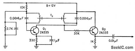
Oscillator Q1 can be adjusted to within 0.1 cps of desired frequency by adjusting length and center thickness of rod made from modified Elinvar constant-modulus material positioned between coils. Emitter-follower Q2 minimizes pulling by variable load. -T. A O. Gross, New Magnetic Rods Simplify Circuits, Electronics, 35:28, p 62-66. (View)
View full Circuit Diagram | Comments | Reading(914)
COLPITTS_1_to_20_MHz_CRYSTAL_OSCILLATOR
Published:2009/7/10 2:21:00 Author:May
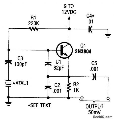
This is a simple Colpitts crystal oscillator for 1 to 20 MHz, can be easily made from junk-box parts(provided that a crystal is handy). (View)
View full Circuit Diagram | Comments | Reading(7521)
UNIJUNCTION_TRANSISTOR_OSCILLATOR
Published:2009/7/19 22:57:00 Author:Jessie
If circuit is broken at X, discharge current of C1 can be used to shut off transistor stage. -A. G. Lloyd, Overload Protection for Transistor Voltage Regulators, Electronics, 33:52, p 56-59. (View)
View full Circuit Diagram | Comments | Reading(856)
SIMPLE_THIRD_OVERTONE_OSCILLATOR
Published:2009/7/10 2:18:00 Author:May
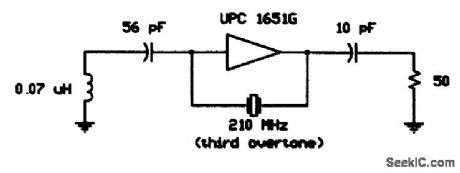
Using a 210-MHz third overtone crystal,this circuit operates directly at the crystal frequency,with210-MHz output and no multiplier stages. (View)
View full Circuit Diagram | Comments | Reading(659)
SIMPLE_FUNDAMENTAL_CRYSTAL_oscILLATOR
Published:2009/7/10 2:17:00 Author:May
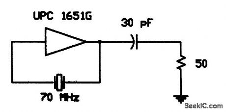
This simple fundamental oscillator uses a μPC1651G IC and two components. The crystal is funda-mental. (View)
View full Circuit Diagram | Comments | Reading(685)
NR_DIODE_AS_R_F_OSCILLATOR
Published:2009/7/19 23:25:00 Author:Jessie
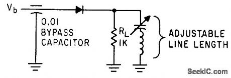
Simple negative-resistance diode circuit can develop several milliwatts at frequencies up to 300 Mc.-A. P. Schmid, Jr., Negative-Resistance Diode Handles High Power, Electronics, 34:34, p 44-46. (View)
View full Circuit Diagram | Comments | Reading(677)
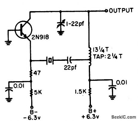
CB_CRYSTAL_OSCILLATOR
Published:2009/7/19 23:24:00 Author:Jessie
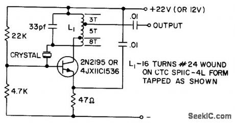
Uses low-cost crystal having high series resistance, up to 30 ohms. Provides adequate output to supply most master oscillator-power amplifier applications. Output tap is arranged to match directly a companion 2N2195 grounded-base amplifier. Crystal is 3rd overtone type.- Transistor Manual, Seventh Edition, General Electric Co., 1964, p 211. (View)
View full Circuit Diagram | Comments | Reading(954)
SATURABLE_REACTOR_OSCILLATOR
Published:2009/7/19 23:21:00 Author:Jessie
Timebase integration of a variable is performed by counting cycles of saturable-reactor oscillator whose frequency is proportional to the variable. linearity is within 1% of full scale.-L. W. Langley, Saturable-Core Oscillator Integrates Gas-Flow Data, Electronics, 32:4, p 42-43. (View)
View full Circuit Diagram | Comments | Reading(1197)
| Pages:27/54 At 202122232425262728293031323334353637383940Under 20 |
Circuit Categories
power supply circuit
Amplifier Circuit
Basic Circuit
LED and Light Circuit
Sensor Circuit
Signal Processing
Electrical Equipment Circuit
Control Circuit
Remote Control Circuit
A/D-D/A Converter Circuit
Audio Circuit
Measuring and Test Circuit
Communication Circuit
Computer-Related Circuit
555 Circuit
Automotive Circuit
Repairing Circuit