
Oscillator Circuit
Index 37
DIODE_SWITCHED_CRYSTALS
Published:2009/7/3 4:11:00 Author:May
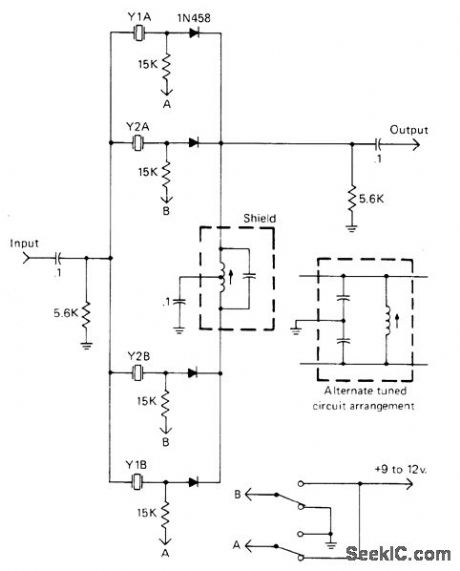
1N458 diodes switch crystals in pairs to provide two different degrees of selectivity for 455-kHz IF filter, For 500-Hz bandwidth in amateur communication receiver, spacing between crystal frequencies should be 300 Hz, which is obtained with 455.150 kHz for Y1A and 454.850 kHz for Y1B.Provides adequate CW selectivity for transceiver having good SSB filter.-J. J. Schultz, Economical Diode-Switched Crystal Filters, CQ, July 1978, p 33-35 and 91.
(View)
View full Circuit Diagram | Comments | Reading(876)
LIGHT_SENSITIVE_OSCILLATOR
Published:2009/7/3 2:39:00 Author:May
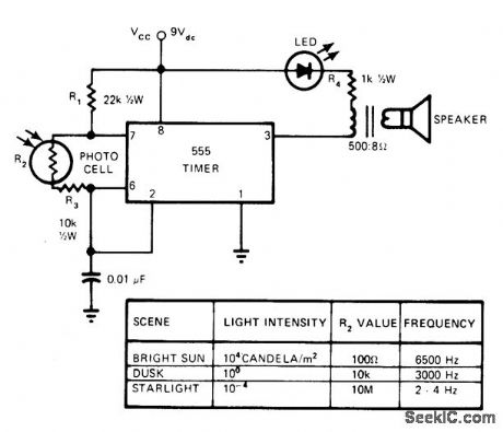
Uses 555 timer connected so frequency increases directly with intensity of light. Free-running frequency and duty cycle of timer operating in astable mode are controlled by two resistors and one capacitor. R3 sets upper frequency limit at about 6.5 kHz, and dark resistance of photocell R2 sets lower limit at about 1 Hz. Loudspeaker provides audio output, while LED flashes for visual indication when frequency goes below about 12 Hz.Applications include detection of lightning flashes, use as optical radar for blind, and use as sunrise alarm.-C. R. Graf, Build a Light Sensitive Audio Oscillator, EDN Magazine, Aug. 5, 1976, p 83. (View)
View full Circuit Diagram | Comments | Reading(1340)
STROBE_TONE_BURST_GENERATOR
Published:2009/7/2 21:30:00 Author:May
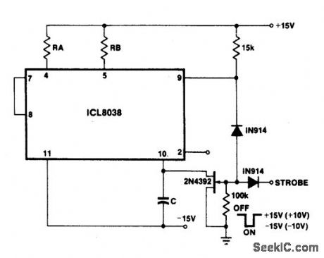
With a dual supply voltage, the external capacitor on pin 10 can be shorted to ground to halt the 8038 oscillation. The circuit uses a FET switch and diode ANDed with an input strobe signal to allow the output to always start on the same slope. (View)
View full Circuit Diagram | Comments | Reading(0)
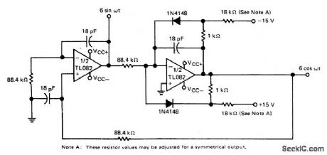
100_kHz_QUADRATURE_OSCILLATOR
Published:2009/7/2 21:27:00 Author:May
View full Circuit Diagram | Comments | Reading(748)
CMOS_INTERFACE_USING_OPTOlSOLATOR
Published:2009/7/2 20:18:00 Author:May
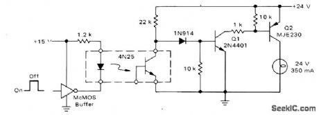
Provides logic control of 350-mA lamp. High level on input of typical CMOS inverter energizes 4N25 optoisolator, to clamp Q1 off. This removes drive from Q2, deenergizing load.Logic 0 at input reverses conditions, tuming on lamp. With values shown, 10 mA at optoisolator input controls completely isolated 350-mA load.-A. Pshaenich, Interface Techniques Between lndustrial Logic and Power Devices, Motorola, Phoenix, AZ, 1975, AN-712A, p 16. (View)
View full Circuit Diagram | Comments | Reading(2319)
95_MHz_TUNABLE_CRYSTAL
Published:2009/7/2 9:27:00 Author:May
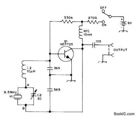
Clapp oscillator with inductance in series with crystal can be tuned with C2 as much as 100 kHz below rated frequency of crystal. Based on making crystal act as capacitive reactance below its series-resonant frequency. Circuit can be adapted to other amateur bands by keeping reactances of various components approximately the same.-L. Lisle, The Tunable Crystal Oscillator, QST, Oct. 1973, p 30-32. (View)
View full Circuit Diagram | Comments | Reading(1227)
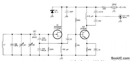
10_MHz_VFO
Published:2009/7/2 9:25:00 Author:May
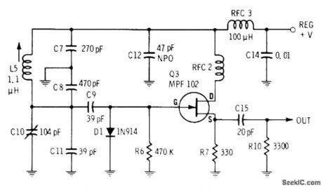
Values shown for high-stability variable-frequency oscillator give operation in 10-MHz range. Stable supply voltage is essential. Use silver mica capacitors in gate circuit for maximum stability.-E.M. Noll, FET Principles Experiments, and Projects, Howard W. Sams, Indianapolis, IN, 2nd Ed., 1975, p 193-194. (View)
View full Circuit Diagram | Comments | Reading(1546)
465_kHz_FOR_IF_TUNE_UP
Published:2009/7/2 9:24:00 Author:May
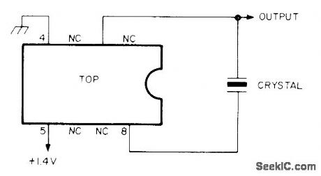
Simple crystal oscillator using National LM3909N is adjusted to exactly desired frequency with capacitor in series with pin 8. Drain from AA cell is less than 0.5 mA at 1.2 V. Use 465-kHz crystal and couple oscillator to receiver input with 100-pF capacitor. With 100-kHz crystal, circuit will generate strong harmonics beyond 30 MHz; to zero-beat with WWV, use about 10 pF in series with erystal.-I. Queen, Simple Crystal Oscillator, Ham Radio, Nov, 1977, p 98. (View)
View full Circuit Diagram | Comments | Reading(1423)
5_55_MHz_VFO
Published:2009/7/2 9:23:00 Author:May
Used in solid-state five-band communication receiver. Temperature compensation is provided by 20-pF trimmer that sets band center L1 is 34 turns No.24 on Amidon T50-6 toroid core.-P. Moroni, Solid-State Communications Receiver Ham Radio, Oct,1975, P 32-41 (View)
View full Circuit Diagram | Comments | Reading(2127)
20_100_MHz_OVERTONE_CRYSTAL
Published:2009/7/2 9:23:00 Author:May
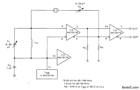
Adiustable tank circuit C1L1 ensures operation at desired crystal overtone. Reference voltage for differential amplifier is supplied internally by Motorola 10116 IC and is nominally-1.3 V.-B. Blood, IC Crystal Controlled Oscillators, Motorola, Phoenix, AZ, 1977, AN-417B, P 3. (View)
View full Circuit Diagram | Comments | Reading(1101)
TTL_459_MHz_CRYSTAL
Published:2009/7/2 9:22:00 Author:May
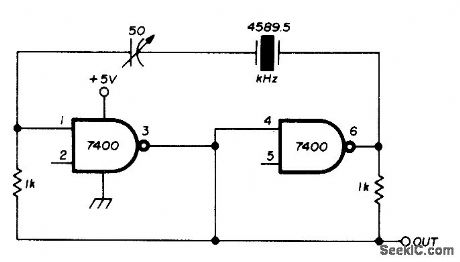
Uses FT243 crystat hand-ground to 4.5895 MHz, with 50-pF series capacitor allowing frequency to be trimmed to exactly 4.59 MHz for use in AFSK generator.-J. Nugues, AFSK Generator, Ham Radio, July 1976, p 69. (View)
View full Circuit Diagram | Comments | Reading(899)
4_MHz_CRYSTAL
Published:2009/7/2 9:21:00 Author:May
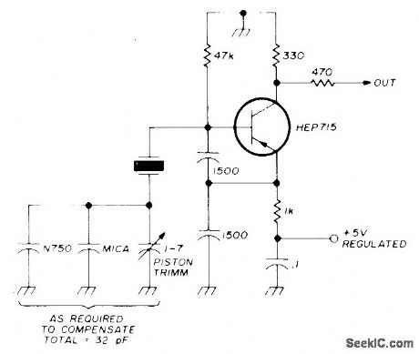
High-stability crystal oscillator usestwo 1500-pF capacitors to swamp out internal lmpedance changes that might cause frequency drift. For best stability when used as frequency standard, choose high-accuracy 4-MHz crystal.-B. Kelley, Universal Frequency Standard, Ham Radilo, Feb. 1974, p 40-47. (View)
View full Circuit Diagram | Comments | Reading(2451)
200_MHz_WITH_OSCI_LLATOR_DOUBLER
Published:2009/7/2 9:21:00 Author:May
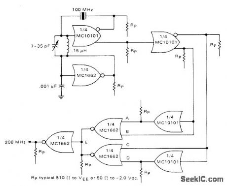
One section of Motorola MCI0101 is connected as 100-MHz crystal oscillator having crystal in series with feedback loop. LC tank circuit tunes 100-MHz harmonic of crystal and can be used to adjust circuit to exact frequency. Second section of IC serves as buffer and gives complementary 100-MHz signals for frequency doubler having two MC10101 gates as phase shifters and two MC1662 NOR gates. Outputs of MC1662s are wired-OR connected to give 200-MHz signal. One of remaining MC1662 gates is used as bias generator for oscillator.-B. Blood, IC Crystal Controlled Oscillators, Motorola, Phoenix, AZ, 1977, AN-417B, p 5. (View)
View full Circuit Diagram | Comments | Reading(976)
STABLE_CRYSTAL
Published:2009/7/2 9:19:00 Author:May
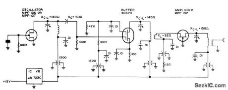
Stability is good enough for microwave transmitter frequency control. Will operate with fundamental or overtone crystals from 1.6 to 160 MHz, whh coils and capacitors being chosen for frequency in use.-Circuits, 73 Magazine, May 1973, p 105. (View)
View full Circuit Diagram | Comments | Reading(1416)
TIMER_AS_OSCILLATOR
Published:2009/7/2 9:18:00 Author:May
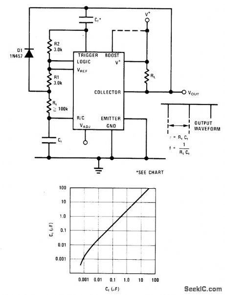
Output of National LM122 timerisfed back to trigger input through capacitor to give self-starting oscillator. Frequency is 1/RtCt. Output is narrow negative pulse havipg duration of about 2R2Cf. Conservative value for Cf for optimum frequency stability can be chosen from graph based on size of timing capacitor Ct.-C. Nelson, Versatile Timer Operates from Microseconds to Hours, National Semiconductor, Santa Clara, CA, 1973, AN-97, p 10. (View)
View full Circuit Diagram | Comments | Reading(761)
7_MHz_±_50_kHz
Published:2009/7/2 9:17:00 Author:May
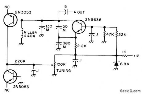
Requires no tuning capacitors. Collector-to-base iunctions of two 2N3053 transistors perform function of varactor diodes to provide tuning over range of about 50 kHz centered on 7 MHz. Capacitors marked M should be mica.-An Accessory VFO-the Easy Way, 73 Magazine, Aug. 1975, p 103 and 106-108. (View)
View full Circuit Diagram | Comments | Reading(1264)
PRECISION_VFO
Published:2009/7/2 9:15:00 Author:May
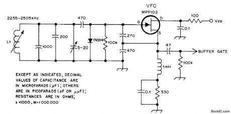
Permeability-tuned oscillator provides stability and linearity at low cost for receivers with 160-meter tunable IF stages. L1 has 28 turns No. 36 enamel closewound on J. W. Miller form 64A022.2. Article covers construction of tuning dial, incuding contouring of L1 core to give good dial linearity. Frequency coverage is 2.255-2.509 MHz. Direct-reading dial is accurate within 1.5 kHz over entire 250-kHz tuning range.-W. A. Gregoire, Jr., A Permeability-Tuned Variable-Frequency Oscillator, QST, March 1978, p 26-28. (View)
View full Circuit Diagram | Comments | Reading(2359)
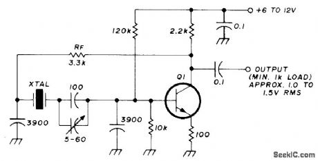
20_500_kHz_CRYSTAL
Published:2009/7/2 9:15:00 Author:May
Series-mode oscillator requires no tuned circuit, gives choice of sine or square output, and has good frequency and mode stability. Works nicely with troublesome FT241 crystals. If any crystal fails to start reliably, increase R1 to 270 ohms and R2 to 3.3K. For squire-wave operation, C1 is 1-μF nonelectrolytic. Omit C1 for sine-wave operation; harmonic output is then quite low, whh second harmonic typically -30 dB. Output is about 1.5-VRMS sine wave or 4-V square wave.-R. Harrison, Survey of Crystal Oscillators, Ham Radio, March 1976, p 10-22. (View)
View full Circuit Diagram | Comments | Reading(1585)
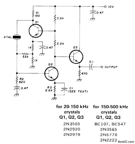
50_500_kHz_CRYSTAL
Published:2009/7/2 9:13:00 Author:May
Parallel-mode low-frequency oscillator makes excellent BFO for 455 kHz. If oscillator will not start, reduce value of feedback resistor RF. Increasing RF reduces harmonic output, but oscillator may then take up to 20 s to reach full output. For crystals with specified load capacitance of 30 or 50 pF, remove 100-pF capacitor C1 in series with crystal. Q1 is 2N2920, 2N2979, 2N3565, 2N3646, 2N5770, BC107, or BC547.-R. Harrison, Survey of Crystal Oscillators, Ham Radio, March 1976, p 10-22. (View)
View full Circuit Diagram | Comments | Reading(5038)
48_MHz
Published:2009/7/2 9:12:00 Author:May
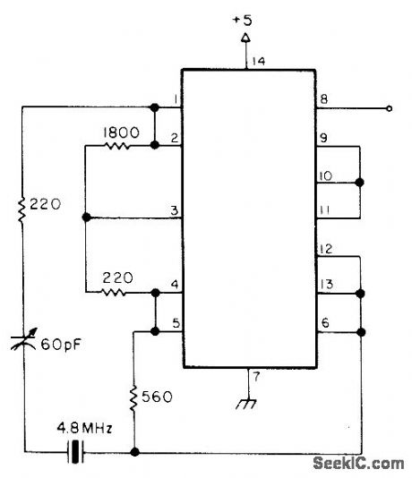
Uses all four sections of 7400 quad dual-input NAND gate to give 4.8 MHz output at pin 8, as harmonic-rich square wave. Can cause severe television interference during testing. Article gives five other crystal oscillator circults using same IC.-A. MacLean, How Do You Use ICs?, 73 Magazine, Oct. 1976, p 38-41. (View)
View full Circuit Diagram | Comments | Reading(1261)
| Pages:37/54 At 202122232425262728293031323334353637383940Under 20 |
Circuit Categories
power supply circuit
Amplifier Circuit
Basic Circuit
LED and Light Circuit
Sensor Circuit
Signal Processing
Electrical Equipment Circuit
Control Circuit
Remote Control Circuit
A/D-D/A Converter Circuit
Audio Circuit
Measuring and Test Circuit
Communication Circuit
Computer-Related Circuit
555 Circuit
Automotive Circuit
Repairing Circuit