
Oscillator Circuit
Index 31
Voltage_controlled_oscillator_using_an_MC1648
Published:2009/7/20 23:18:00 Author:Jessie
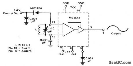
Voltage-controlled oscillator using an MC1648. This VCO is tunable from 110 MHz to 145 MHz. The control voltage range is 1.8 volts at 110 MHz to 5 volts at 145 MHz (courtesy Motorola Semiconductor products Inc.). (View)
View full Circuit Diagram | Comments | Reading(4731)
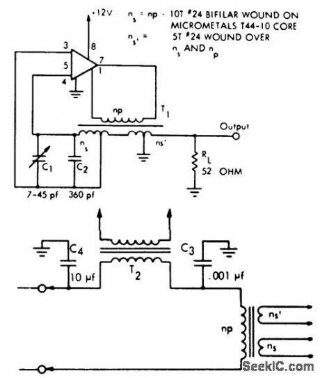
100_MHz_oscillator_and_buffer
Published:2009/7/20 23:17:00 Author:Jessie
100 MHz oscillator and buffer (courtesy Texas Instruments Incorporated). (View)
View full Circuit Diagram | Comments | Reading(861)
1_second_reference_oscillator
Published:2009/7/20 23:15:00 Author:Jessie
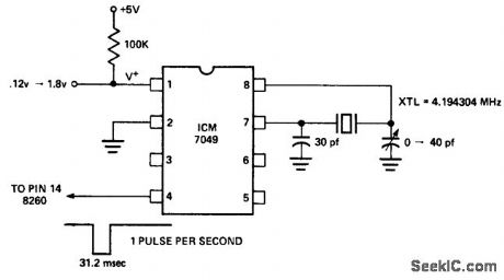
1-second reference oscillator. This circuit is ideal for clock circuits where no 60-hertz line is available (courtesy Intersil, Inc.). (View)
View full Circuit Diagram | Comments | Reading(934)
Watchdog_light_sensitive_oscillator
Published:2009/7/20 23:11:00 Author:Jessie
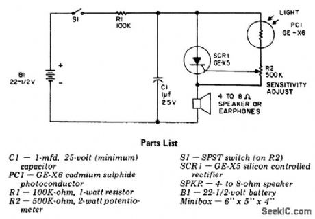
Watchdog light-sensitive oscillator. The basic circuit is a relaxation oscillator that sounds an alarm through a speaker or earphone. R2 is set for a bias current just below the firing level (courtesy General Electric Company). (View)
View full Circuit Diagram | Comments | Reading(1146)
Voltage_controlled_sine_wave_oscillator_for_up_to_50_kHz
Published:2009/7/20 23:10:00 Author:Jessie
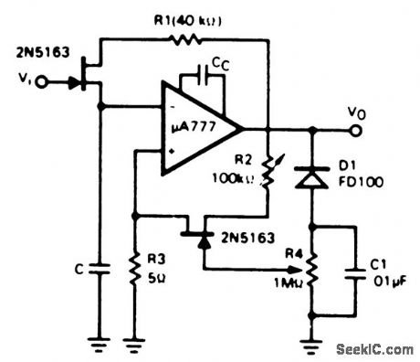
Voltage-controlled sine-wave oscillator for up to 50 kHz. For frequencies of 10 kHz to 50 kHz capacitor Cc should be 3 pF. For frequencies less than 10 kHz capacitor Cc should be 30 pF. Select capacitor C according to desired frequency, or make it variable from zero to 5 μF (courtesy Fairchild Semiconductor). (View)
View full Circuit Diagram | Comments | Reading(1292)
200_MHz_crystal_oscillator
Published:2009/7/20 23:07:00 Author:Jessie
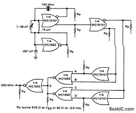
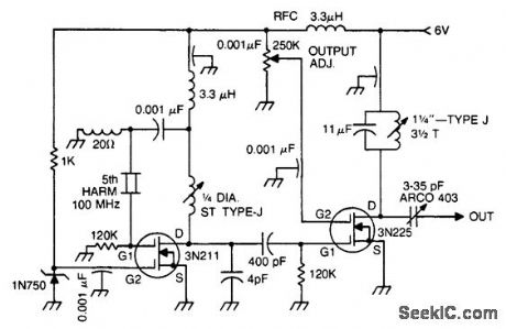
200 MHz crystal oscillator. This circuit incorporates a 100 MHz oscillator and a frequency doubler. VEE is -5.2 volts (courtesy Motorola Semiconductor Products Inc.). (View)
View full Circuit Diagram | Comments | Reading(1215)
Digitally_programmed_oscillator
Published:2009/7/20 22:54:00 Author:Jessie
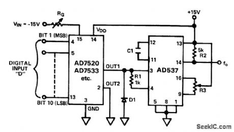
Digitally programmed oscillator. The circuit uses an AD537 monolithic V/F converter and an AD7520 multiplying D/A convener. It is a programmable square wave frequency source with excellent linearity in the range of0 to 100 kHz (courtesy Analog Devices, Inc.). (View)
View full Circuit Diagram | Comments | Reading(800)
Quadrature_oscillator_using_an_ECG947_dual_operational_amplifier_IC
Published:2009/7/20 22:53:00 Author:Jessie
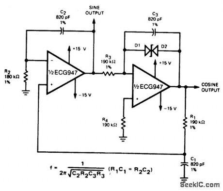
Quadrature oscillator using an ECG947 dual operational amplifier IC. The ECG947 is short-circuit proof and requires no external components for frequency compensation (courtesy GTE Sylvania Incorporated). (View)
View full Circuit Diagram | Comments | Reading(1395)
Electronic_organ_master_oscillator_using_an_ECG1026_thin_film_hybrid_module
Published:2009/7/20 22:51:00 Author:Jessie
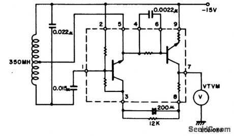
Electronic organ master oscillator using an ECG1026 thin-film hybrid module. Output is taken at pin 7, where the VTVM is shown connected to test output voltage level (courtesy GTE Sylvania Incorporated). (View)
View full Circuit Diagram | Comments | Reading(680)
10_MHz_oscillator_using_a_single_ECG703A_chip_that_can_be_used_as_a_short_range_transmitter
Published:2009/7/20 22:50:00 Author:Jessie
10 MHz oscillator using a single ECG703A chip that can be used as a short range transmitter. it is possible to modulate the oscillator by inserting the audio modulator shown between pin 1 and the tank circuit (courtesy GTE Sylvania Incorporated). (View)
View full Circuit Diagram | Comments | Reading(606)
STABILIZED_HORIZONTAL_OSCILLATOR
Published:2009/7/20 21:04:00 Author:Jessie
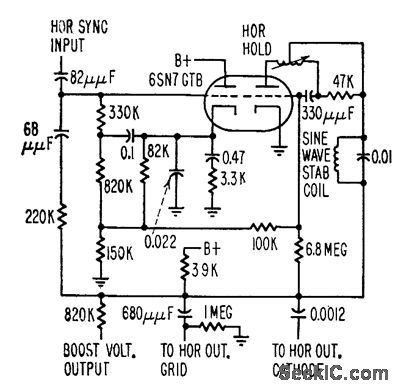
Sine-wave stabilization or ringing coil pulls Synchroguide horizontal oscillator frequency back to correct value when lube or other components drift in value.-W. E. Babcock, Unusual Tube Effects Cause Circuit Troubles, Electronics, 31:37, p 90-93. (View)
View full Circuit Diagram | Comments | Reading(1071)
PROGRAMMABLE_FREQUENCY_SINE_WAVE_OSCILLATOR
Published:2009/7/9 1:26:00 Author:May
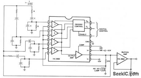
This Wien-bridge oscillator is very popular for signal generators, since it is easily turned over a wide frequency range, and has a very low distortion sine-wave output. The frequency determining networks can be designed from about 10 Hz to greater than 1 MHz; the output level is about 6.0-V rms. By substituting a programmable attenuator for the buffer amplifier, a very versatile sine-wave source for automatic testing, etc. can be constructed.
(View)
View full Circuit Diagram | Comments | Reading(931)
HC_BASED_OSCILLATORS
Published:2009/7/9 1:24:00 Author:May
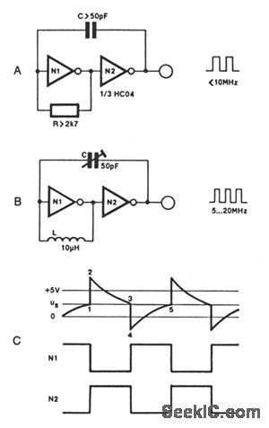
Two inverters, one resistor, and one capacitor are all that is required to make a HC(T)-based oscillator that gives reliable operation up to about 10 MHz. The use of two HC inverters produces a fairly symmetrical rectangular output signal. In the same circuit, HCT inverters give a duty factor of about 25%, rather than about 50%, since the toggle point of an HC and an HCT inverter is 1/2 VCC, and slightly less than 2 V, respectively. If the oscillator is to operate above 10 MHz, the resistor is replaced with a small inductor, as shown in Fig.68-4B.
The output frequency of the circuit in Fig. 68-4A is given as about 1/1.8rc, and can be made variable by connecting a 100-KΩ potentiometer in series with R. The solution adopted for the oscillator in Fig. 68-4B is even simpler: C is a 50-pF trimmer capacitor.
(View)
View full Circuit Diagram | Comments | Reading(884)
RLC_OSCILLATOR
Published:2009/7/9 1:23:00 Author:May
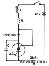
A positive transient, such as the power switch closing, charges C through L to a voltage above the supply voltage, if Q is sufficient. When the current reverses, the diode blocks and triggers the SCS. As the capacitor discharges, the anode gate approaches ground potential, depriving the anode of holding current. This turns off the SCS, and C charges to repeat the cycle. (View)
View full Circuit Diagram | Comments | Reading(839)
FIXED-FREQUENCY_VARIABLE_DUTY_CYCLE_OSCILLATOR
Published:2009/7/9 1:21:00 Author:May
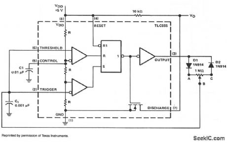
In a basic astable timer,configuration periods t1 and t2 are not controlled independently. The lack of control make it difficult to maintain a constant period,T,if either t1 or t2 is varied.In this circuit,charge RAB and discharge RBC resistance are determined by the position of common wiper arm B of the Potentiometer so,it is possible to adjust the duty-cycle by adjusting t1 and t2 Proportionately,without changing period T.
At start-up,the voltage across G is less than the trigger level voltage (1/2 VDD),causing the timer to be triggered via pip 2,The output of the timer at m 3 Increases,turning off the discharge transistor at pin 7 and allowina Ct to charge through diode D1 and resitance RAB.When capacitor Ct charges to upper threshold voltage 2/3 VDD,the flip-flop is reset and the output at pin 3 decreases through diode D2 and resistor RBC.When the voltage at pin 2 reaches 1/3 VDD,the lower threshold or trigger level,the timer triggers.again and the cycle is repeated.In this circuit,the oscillator frequency remains fixed and the duty cycle is adjustable from less than 0.5% to greater than 99.5%. (View)
View full Circuit Diagram | Comments | Reading(1412)
Multicrystal_RF_oscillator_for_the_100_kHz_to_20_MHz_range
Published:2009/7/20 23:46:00 Author:Jessie
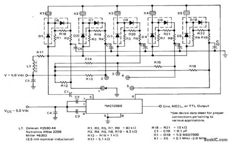
Multicrystal RF oscillator for the 100 kHz to 2.0 MHz range (courtesy Motorola Semiconductor Products Inc.). (View)
View full Circuit Diagram | Comments | Reading(734)
Voltage_controlled_sine_wave_oscillator
Published:2009/7/20 23:55:00 Author:Jessie
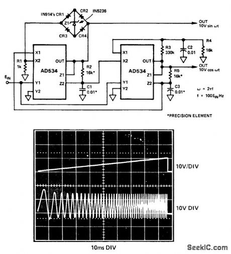
Voltage-controlled sine-wave oscillator. Two AD534 multipliers are used to form integrators with controllable time constants in a second-order differential-equation feedback loop. The waveform shows the VCO's response to a ramp input (courtesy Analog Devices, Inc.). (View)
View full Circuit Diagram | Comments | Reading(0)
DISCRETE_SEQUENCE_OSCILLATOR
Published:2009/7/9 1:15:00 Author:May

The swept-frequency oscillator offers an inexpensive source of discrete frequencies for use in testing digital circuits. In this configuration, the circuit generates an 80-second sequence of eight frequencies, dwelling for 10 seconds on each frequency. You can change the dwell time or the number of frequencies.Frequencies can range from 0.005 Hz to 1 MHz.
The programmable crystal oscillators, PXOs, IC2 and IC4 can each generate 57 frequencies in response to an 8-bit external code. IC2 contains a 1-MHz crystal and produces a 0.05-Hz output. IC4 contains a 600-kHz crystal; its output changes in response to the combined outputs of the 12-stage binary counter IC3 (Q1 and Q2) and the PXO IC2.
To generate more frequencies, you can use one or more of IC3's outputs, (Q3, Q4, Q5) to drive one or more of IC4's inputs (P4, P5, P6). Similarly, you can rewire IC2 or drive it with other logic to control the duration of each frequency. IC1, a monostable multivibrator, provides a system reset. It initiates the sequence shown, beginning at 60 Hz, in response to a positive pulse. (View)
View full Circuit Diagram | Comments | Reading(864)
50DUTY_CYCLE_OSCILLATOR
Published:2009/7/9 1:34:00 Author:May

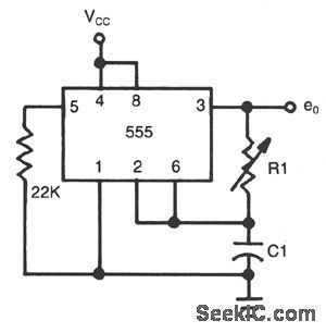
Frequency of oscillation depends on the R1/C1 time constant and allows frequency adjustment byvarylng R1. (View)
View full Circuit Diagram | Comments | Reading(879)
HCU_HCT_BASED_OSCILLATOR
Published:2009/7/9 1:33:00 Author:May
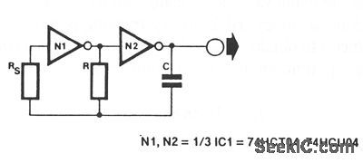
When frequency stability is not of prime importance, a simple, yet retable, digital clock oscillator can be made with the aid of relatively few components. High-speed CMOS (HCU/HCT) inverters or gates with an inverter function are eminently suitable to make such oscillators, thanks to their low power con-sumption, good output signal definition, and extensive frequency range.
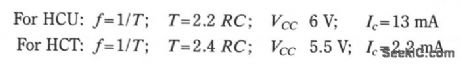
The circuit as shown uses two inverters in a 74HCT04 or 74HCU04. The basic design equations are:
With RS and R calculated for a given frequency and value of C, both resistors can be realized as presets to enable precise setting of the output frequency and the duty factor. Do not forget, however, to fit small series resistors in series with the presets, in observance of the minimum values for R and RS as given in the design equations. The values quoted for IC are only valid if the inputs of the remaining gates are g fillnded.
(View)
View full Circuit Diagram | Comments | Reading(1559)
| Pages:31/54 At 202122232425262728293031323334353637383940Under 20 |
Circuit Categories
power supply circuit
Amplifier Circuit
Basic Circuit
LED and Light Circuit
Sensor Circuit
Signal Processing
Electrical Equipment Circuit
Control Circuit
Remote Control Circuit
A/D-D/A Converter Circuit
Audio Circuit
Measuring and Test Circuit
Communication Circuit
Computer-Related Circuit
555 Circuit
Automotive Circuit
Repairing Circuit