
Oscillator Circuit
Index 30
5_V_OSCILLATOR
Published:2009/7/9 1:51:00 Author:May

Consistently self-starting and yet capable of operating from over 1 Hz to 10 MHz, this low-cost oscillator requires only five components. Calculate the period of oscillation by using this relationship: P = 5 ×10³ C sec when C= C1=C2. Bychanging the ratio of C1 to C2, the duty cycle can be as low as 20%. (View)
View full Circuit Diagram | Comments | Reading(1095)
PRECISION_VOLTAGE_CONTROLLED_OSCILLATOR
Published:2009/7/9 1:50:00 Author:May
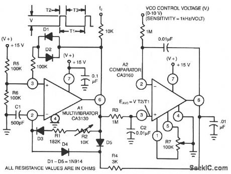
This circuit uses a CA3130 BiMOS op amp as a multivibrator and CA3160 BiMOS op amp as a com-parator. The oscillator has a sensitivity of 1 kHz/V, with a tracking error in the order of 0.02%, and a temperature coefficient of 0.01%℃. (View)
View full Circuit Diagram | Comments | Reading(0)
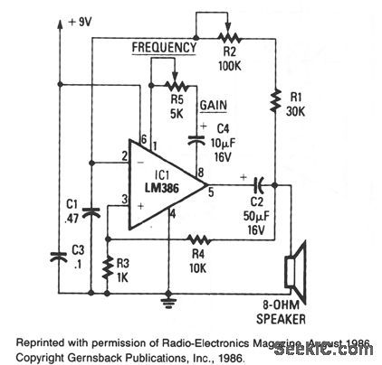
CODE_PRACTICE_OSCILLATOR
Published:2009/7/9 1:49:00 Author:May
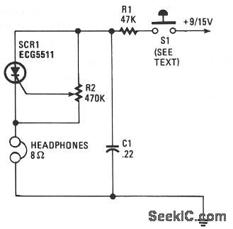
Capacitor C1 charges through resistor R1, and when the gate level established by potentiometer R2 is high enough, the SCR is triggered. Current flows through the SCR and earphones, discharging C1. The anode voltage and current drop to a low level, so the SCR stops conducting and the cycle is repeated. Resistor R2 lets the gate potential across C1 be adjusted, which charges the frequency or tone. Use a pair of 8-Ω headphones. The telegraph key goes right into the B+ line, 9-V battery. (View)
View full Circuit Diagram | Comments | Reading(0)
CMOS_OSCILLATOR_1
Published:2009/7/9 1:48:00 Author:May

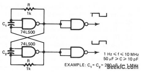
The common clock oscillator in Fig. 68-19A has two small problems: It might not, in fact, oscil-late if the transition regions of its two gates differ. If it does oscillate, it might sometimes oscillate at a slightly lower frequency than its equation predicts because of the fmite gain of the ftrst gate. If the circuit does work, oscillation occurs usually because both gates are in the package and, therefore, have logic thresholds only a few millivolts apart.
The circuit in Fig. 68-19B resolves both prob-lems by adding a resistor and a capacitor. The R2/ C2 network provides hysteresis, thus delaying the onset of gate 1's transition until C1 has enough voltage to move gate 1 securely through its transi-tion region. When gate 1 is finally in its transition region, C2 provides positive feedback, thus rapidly moving gate 1 out of its transition region.
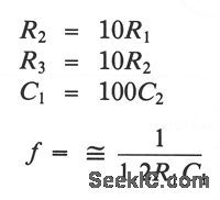
The equations for the oscillator in Fig. 68-19B are:
(View)
View full Circuit Diagram | Comments | Reading(933)
XOR_GATE_OSCILLATOR
Published:2009/7/9 1:44:00 Author:May
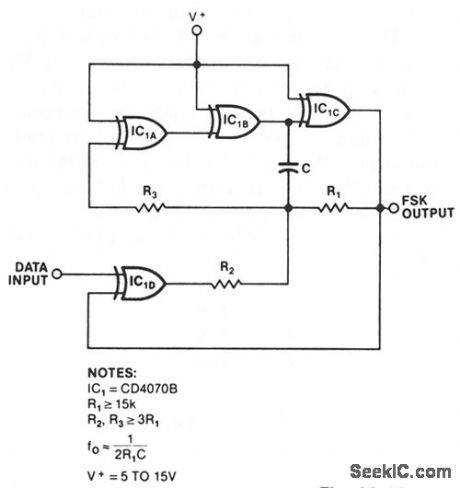
An exclusive-OR gate, IC1D, turns a simple CMOS oscillator into an FSK generator. When the data input increases, IC1D inverts, and negative feedback through R2 lowers the circuit's output frequency. A low input results in positive feedback and a higher output frequency. R1 and C set the oscillator's frequency range, and R2 determines the circuit's frequency shift. To ensure frequency stability, make R3 much greater than R1 and use a high-quality feedback capacitor. The three gates constituting the oscillator itself need not be exclusive-OR types; use any CMOS inverter. (View)
View full Circuit Diagram | Comments | Reading(1445)
CMOS_OSCILLATOR
Published:2009/7/9 1:43:00 Author:May
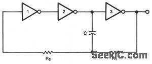
This circuit is guaranteed to oscillate at a frequency of about 2.2/(R1 ×C) if R2 is greater than R1 You can reduce the number of gates further if you replace gates 1 and 2 with a noninverting gate. (View)
View full Circuit Diagram | Comments | Reading(0)
WIEN_BRIDGE_OSCILLATOR
Published:2009/7/9 1:42:00 Author:May
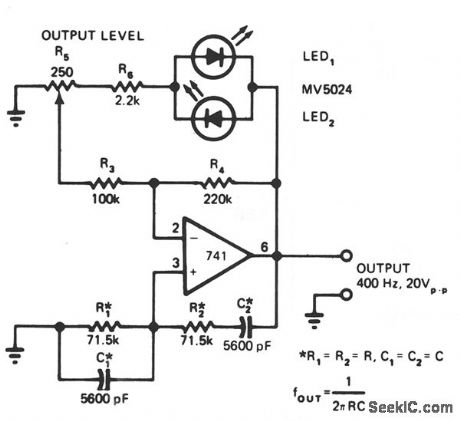
LEDs function as both pilot lamps and as an AGC (automatic gain control) in this unconventional amplitude-stabilized oscillator. (View)
View full Circuit Diagram | Comments | Reading(0)
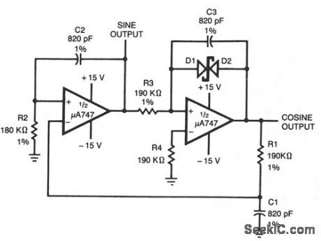
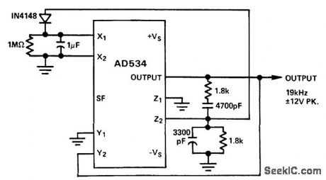
_QUADRATURE_OSCILLATOR
Published:2009/7/9 1:41:00 Author:May
View full Circuit Diagram | Comments | Reading(697)
LOW_FREQUENCY_OSCILLATOR
Published:2009/7/9 1:40:00 Author:May


This simple rc oscillator uses a medium-speed comparator with hysteresis and feedback through R1 and C1 as timing elements. The frequency of oscillation is, at least theoretically, independent from the power supply voltage. If the comparator swings to the supply rails, if the pull-up resistor is much smaller than the resistor Rh, and if the propagation delay is negligible compared to the rc time constant, the oscillation frequency is: (View)
View full Circuit Diagram | Comments | Reading(105)
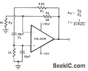
AUDIO_OSCILLATOR
Published:2009/7/9 1:38:00 Author:May
The circuit's frequency of oscillation is f = 2.8/[C1×(R1+ R2)]. Using the values shown, the output frequency can be varied from 60 Hz to 20 kHz by rotating potentiometer R2.
A portion of IC1's output voltage is fed to its noninverting input at pin 3. The voltage serves as a reference for capacitor C1, which is connected to the noninverting input at pin 2 of the IC. That capacitor continually charges and discharges around the reference voltage, and the result is a square-wave output. Capacitor g2 decouples the output.
(View)
View full Circuit Diagram | Comments | Reading(0)
415_MHz_frequency_modulated_oscillator_using_a_3N204_dual_gate_MOSFET
Published:2009/7/20 23:38:00 Author:Jessie
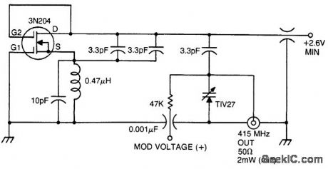
415 MHz frequency-modulated oscillator using a 3N204 dual-gate MOSFET. The 3N212 must be selected for IDSS greater than 20 mA (courtesy Texas Instruments Incorporated). (View)
View full Circuit Diagram | Comments | Reading(711)
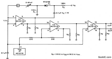
Voltage_controlled_oscillator
Published:2009/7/20 23:40:00 Author:Jessie
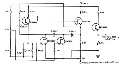
Voltage-controlled oscillator. This three-section phase-shift oscillator produces a good sine wave that is linear over the range indicated (courtesy Motorola Semiconductor Products Inc.). (View)
View full Circuit Diagram | Comments | Reading(0)
LAST_CYCLE_COMPLETING_GATED_OSCILLATOR
Published:2009/7/9 1:36:00 Author:May
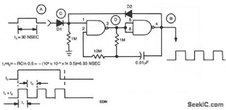
Regenerative feedback at C enables the oscillator to complete its timing cycle, rather than immediately shutting it off. The IC used was a CD4011AE, although an equivalent will work. (View)
View full Circuit Diagram | Comments | Reading(925)
Voltage_controlled_crystal_oscillator
Published:2009/7/20 23:43:00 Author:Jessie
Voltage-controlled crystal oscillator. Operating range is 1 MHz to 20 MHz depending on the selected crystal and tank tuning. Tunign range is from zero to 25 volts. It is possible to make the tuning range from zero to -25 volts by reversing the varactor (courtesy Motorola Semiconductor Products Inc.). (View)
View full Circuit Diagram | Comments | Reading(0)
Voltage_controlled_oscillator_for_FM_operation_using_a_2N4416
Published:2009/7/20 23:37:00 Author:Jessie
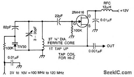
Voltage-controlled oscillator for FM operation using a 2N4416 (courtesy Texas Instruments Incorporated). (View)
View full Circuit Diagram | Comments | Reading(1215)
HIGH_FREQUENCY_OSCILLATOR
Published:2009/7/9 1:35:00 Author:May
Intended primarily as a building block for a QRP transmitter, this 20-MHz oscillator delivered a clean 6-V, pk-pk signal into a 100-Ω load.
(View)
View full Circuit Diagram | Comments | Reading(868)
Stabilized_Wien_bridge_oscillator
Published:2009/7/20 23:36:00 Author:Jessie
Stabilized Wien bridge oscillator (courtesy Analog Devices, Inc.). (View)
View full Circuit Diagram | Comments | Reading(0)
Overtone_crystal_oscillator_with_operating_range_of_20_MHz_to_100_MHz_depending_on_crystal_selection_and_tank_tuning
Published:2009/7/20 23:32:00 Author:Jessie
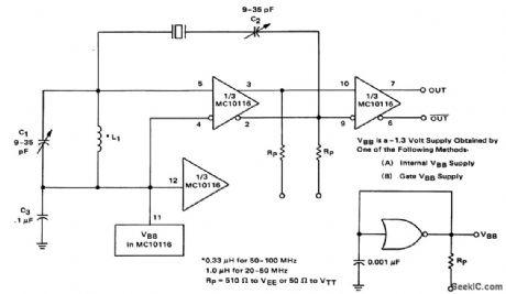
Overtone crystal oscillator with operating range of 20 MHz to 100 MHz depending on crystal selection and tank tuning. VEE is -5.2 volts (courtesy Motorola Semiconductor Products Inc.). (View)
View full Circuit Diagram | Comments | Reading(781)
Multicrystal_RF_oscillator_for_the_20_MHz_to_20_MHz_range
Published:2009/7/20 23:30:00 Author:Jessie
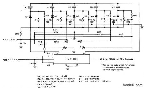
Multicrystal RF oscillator for the 2.0 MHz to 20 MHz range (courtesy Motorola Semiconductor Products Inc.). (View)
View full Circuit Diagram | Comments | Reading(920)
Fundamental_crystal_oscillator_for_1_MHz_to_20_MHz
Published:2009/7/20 23:28:00 Author:Jessie
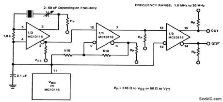
Fundamental crystal oscillator for 1 MHz to 20 MHz. VEE is -5.2 volts (courtesy Motorola Semiconductor Products Inc.). (View)
View full Circuit Diagram | Comments | Reading(739)
| Pages:30/54 At 202122232425262728293031323334353637383940Under 20 |
Circuit Categories
power supply circuit
Amplifier Circuit
Basic Circuit
LED and Light Circuit
Sensor Circuit
Signal Processing
Electrical Equipment Circuit
Control Circuit
Remote Control Circuit
A/D-D/A Converter Circuit
Audio Circuit
Measuring and Test Circuit
Communication Circuit
Computer-Related Circuit
555 Circuit
Automotive Circuit
Repairing Circuit