
Oscillator Circuit
Index 35
SURE_STARTING_CRYSTAL
Published:2009/7/6 0:50:00 Author:May
Loop-within-a-loop oscillator design ensures reliable starting without use of critical components Frequency depends on crystal, which can be anywhere in range from 1 to 20 MHz IC can be 54L00 for 1-2 MHz、standard 54H00 for 2-6 MHz, and 54H00 or 54S00 for 6-20 MHz. Temperature stability is adequate for crystal clocks and other digital-system applications.-J. E. Buchanan, Crystal-Oscillator Design Eliminates Start-Up Problems, EDN Magazine, Feb. 20, 1978, p 110. (View)
View full Circuit Diagram | Comments | Reading(980)
LOW_DRIFT_7_MHz_VFO
Published:2009/7/6 0:48:00 Author:May
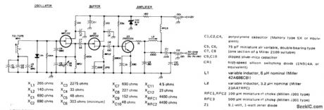
Low-drift solid-state design for 40-meter band has maximum change of only 25 Hz from cold start to full warm-up at 25℃. After stabilization, maximum hunting is 5 Hz. Drift is minimized by paralleling two or more capacitors in critical parts of circuit. Series-tuned Colpitts oscillator is followed by two buffer stages, with second providing enough amplification for practical amateur work while further improving isolation of oscillator. Low-impedance output network minimizes oscillator pulling from load changes. Article stresses importance of choosing and using components that minimize drift.-D. DeMaw, VFO Design Techniques for Improved Stability, Ham Radio, June 1976, p 10-17. (View)
View full Circuit Diagram | Comments | Reading(2503)
DUAL_FREOUENCY_CRYSTAL
Published:2009/7/6 0:46:00 Author:May
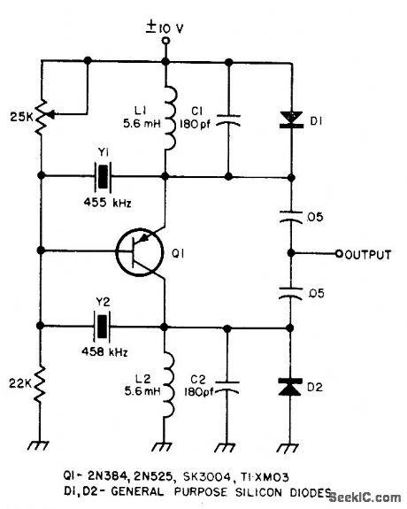
Uses two different crystals, with frequency being changed by reversing supply voltage,Transistor then inverts itself and gain reduces to about 2, which is adequate for oscillator operation Provides two frequencies from single stage with minimum of switching.-Circuits, 73 Magazine, Feb. 1974, p 101. (View)
View full Circuit Diagram | Comments | Reading(992)
IC_CRYSTAL
Published:2009/7/6 0:45:00 Author:May
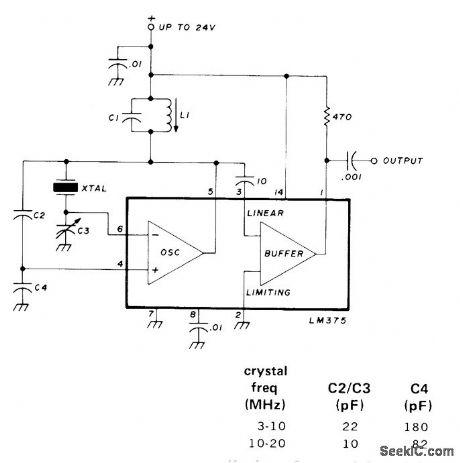
Uses LM375 IC with crystals from 3 to 20 MHz in parallel mode. Will oscillate with only 4-V supply, but output voltage increases with supply voltage, L1 -C1 is resonant at crystal frequency. Adjust L1 only for maximum output, not for trimming frequency. If C3 is 3-30 pF, it can be used to adjust frequency of crystal.-R. Harrison, Survey of Crystal Oscillators, Ham Radio, March 1976, p 10-22. (View)
View full Circuit Diagram | Comments | Reading(1110)
9_MHz_LINEAR_VCO
Published:2009/7/6 0:43:00 Author:May
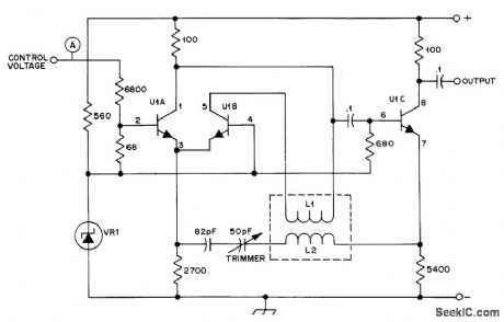
U1A and U1C of RCA CA3046 transistor array form emitter-coupled oscillator. Portion of U1A current is diverted through U1B and L1, producing magnetic flux that reduces effective inductance of resonating coil L2. Output frequency is varied in direct pro portion to voltage applied at A. L1 is 23 turns on 3/4-inch Teflon form 2 inches long, with 4 turns wound between windings for L2. VR1 is 1N3828 6.2-V zener. Circuit must be well grounded and shielded to avoid hum pickup by input, which could modulate output.-D. G. Stephenson, A Second Look at Linear Tuning, OST, March 1977, p 40-41. (View)
View full Circuit Diagram | Comments | Reading(1592)
1_MHz_SERIES_MODE_CRYSTAL
Published:2009/7/6 0:42:00 Author:May
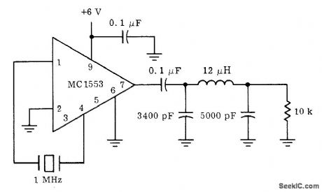
Motorola MC1553 video amplifier provides wide band-width and output swing capability needed for high-frequency master clock or local oscillator in many system designs. Positive feedback is injected through crystal to input pin 1. Output is taken from pin 7 which is buffered internally from oscillator by gain and emitter-follower stages. Brute-force pi filter at output extracts desired fundamental frequency.- A Wide Band Monolithic Video Amplifier, Motorola, Phoenix, AZ, 1973, AN-404 , p 9. (View)
View full Circuit Diagram | Comments | Reading(870)
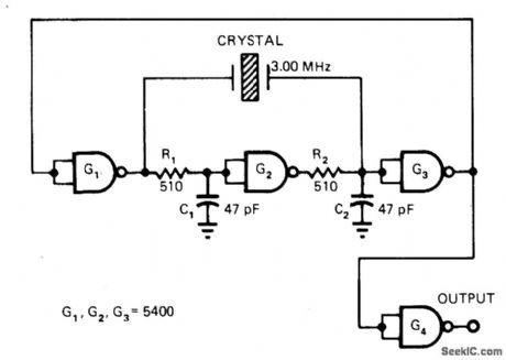
NAND_GATE_TIL_CRYSTAL
Published:2009/7/6 0:40:00 Author:May
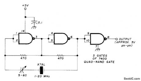
Overcomes problems of poor starting performance and has upper frequency limit of 20 MHz. Suitable for applications requiring high-output aperiodic oscillator. Excellent as frequency marker.-R. Harrison, Survey of Crystal Oscillators, Ham Radio, March 1976, p 10-22. (View)
View full Circuit Diagram | Comments | Reading(2856)
2_20_MHz_VXO
Published:2009/7/6 0:40:00 Author:May
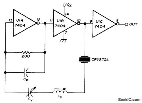
Variable-frequency crystal oscillator plus buffer, using Signetics N7404A hex inverter or equivalent, covers 2-20 MHz. Only three inverters are used, two forming oscillator and one as output buffer. VCC is +5 V. Crystals can operate at fundamental, third, or fifth over-tone. Frequency-limiting capacitor Cp can be 15 pF. Only higher-frequency crystals can be moved useful amounts without creating instability problems. Article gives design equations and tables showing frequencies obtained with various crystals for various values of frequency controls CV (0-100 pF) and LV (0-17 μH).-B. King, Hex Inverter VXO Circuit, Ham Radio, April 1975, p 50-55. (View)
View full Circuit Diagram | Comments | Reading(2840)
90_125_MHz_CRYSTAL
Published:2009/7/6 0:39:00 Author:May
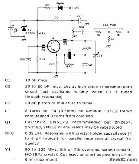
Recmmended for VHF/UHF converters. Output is 5 to 15 mW. Crystal should be high-quality fifth- or seventh-over-tone type. Ferrite bead FB prevents undesired oscillation above 500 MHz. For best stability, allow crystal to operate at its natural series-resonant frequency and use regulated power supply.-J. Reisert, VHF/UHF Techniques, Ham Radio, March 1976, p 44-48. (View)
View full Circuit Diagram | Comments | Reading(985)
50_1000_kHz
Published:2009/7/6 0:36:00 Author:May
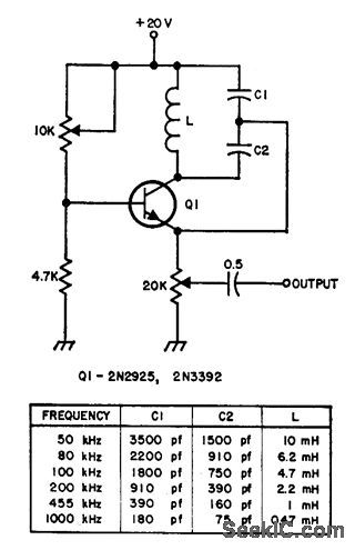
Simple single-transistor circuit provides extremely stable beat-frequency oscillator for which frequency can be changed by using tank-circuit components listed in table.-Circuits, 73 Magazine, Feb. 1974, p 101. (View)
View full Circuit Diagram | Comments | Reading(2156)
150_500_kHz_CRYSTAL
Published:2009/7/6 0:35:00 Author:May
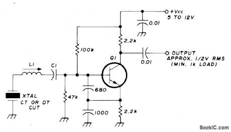
Circuit is series-mode if C1 is 0.01 μF. Parallel-mode crystals can be used if C1 is equal to specified load capacitance (30, 50, or 100 pF) for crystal. Harmonic output is usually better than -30 dB. Circuit is particularly good for crystals prone to oscillate undesirably at twice fundamental frequency. L1 is 800-2000 μH for 150-300 kHz, and 360-1000 μH for 300-500 kHz. Adjusting slug in L1 pulls crystal frequency. Q1 is 2N3563, 2N3564, 2N3693, BC107, BC547, or SE1010.-R. Harrison, Survey of Crystal Oscillators, Ham Radio, March 1976, p 10-22. (View)
View full Circuit Diagram | Comments | Reading(1093)
20_Hz_TO_200_kHz
Published:2009/7/5 23:27:00 Author:May
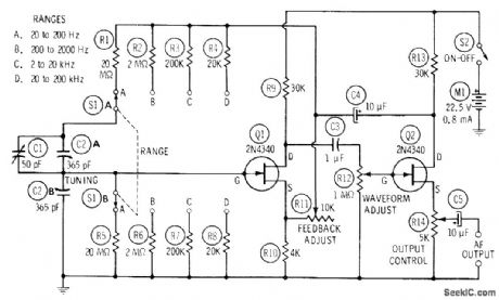
Variable-frequency RC-tuned oscillator uses FETs with Wien-bridge frequency-determining network, Identical resistors accurateto at Ieast 1% are switched in pairs to change range. Dual 365-pF variable capacitor C2 is used for tuning in each range. Can be calibrated against standard audio frequency with CRO set up for Lissajous figures, or calibrated with high-precision AF meter connected to AF output terminals.-R. P. Turner, FET Circuits, Howard W. Sams, Indianapolis, IN, 1977, 2nd Ed., p 132-134. (View)
View full Circuit Diagram | Comments | Reading(1887)
NEGATlVE_RESISTANCE_LED_OSCILLATOR
Published:2009/7/5 23:04:00 Author:May
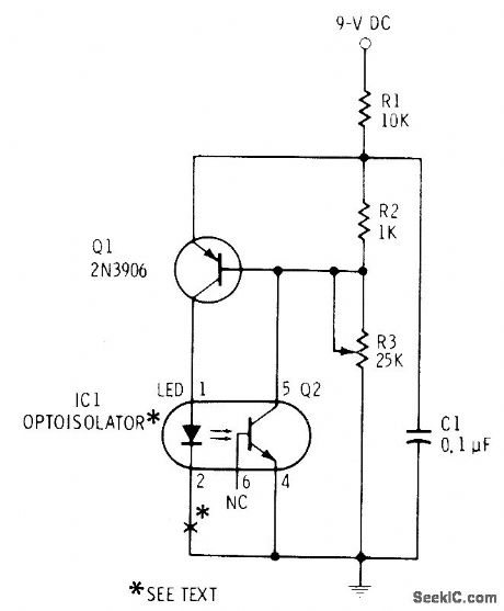
Covers frequency range of about 3.2-8 kHz with values shown. WilI drive Ioudspeaker inserted at point X. For lower frequency (range of 120-1800 Hz) and Iouder sound, change C1 to 1 μF.Negative-resistance portion of circuit indudes Q1, Q2, LED, R2, and R3. Optoisolator can be MCT-2 or equivalent.-F. M, Mims, Electronic Circuitbook 5: LED Projects, Howard W. Sams, Indianapolis, IN, 1976, p 26-29. (View)
View full Circuit Diagram | Comments | Reading(954)
WIDE_ARNGE_VARIABLE_OSCILLATOR
Published:2009/7/5 22:59:00 Author:May
View full Circuit Diagram | Comments | Reading(728)
CODE_PRACTICE_OSCILLATOR
Published:2009/7/5 22:59:00 Author:May
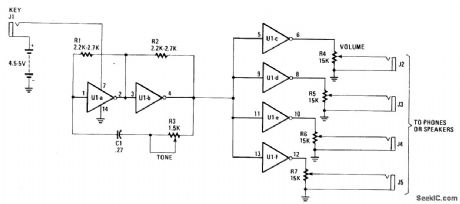
The inexpensive 7404 hex-inverter has enough amplification to handle a wide range of transducers. Closing the key completes the battery circuit and applies four to five volts to the 7404. Bias for the first two inverter amps (U1a and U1b) comes from the two resistors, R1 and R2, connected between their inputs and outputs. The capacitor and rheostat (R3/C1) close the feedback loop from the input to the properly-phased output.
The signal leaving Ulb drives the remaining four inverter amplifiers, U1c through U1f; they, in turn, drive the phones or speakers. The volume control potentiometers, R4-R7, may have any value front 1500 ohms to 10,000 ohms. The smaller values work best when speakers, or low impedance phones, are used. (View)
View full Circuit Diagram | Comments | Reading(0)
INEXPENSIVE_OSCILLATOR_IS_TEMPERATURE_STABLE
Published:2009/7/5 22:57:00 Author:May
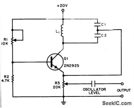
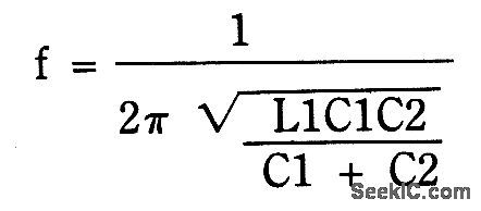
The Colpitts sinusoidal oscillator provides stable output amplitude and frequency from 0°F to +150°F. In addition, output amplitude is large and harmonic distortion is low. Oscillation is sustained by feedback from the collector tank circuit to the emitter. The oscillator's frequency is determined by:
Potentiometer R3 is an output level control.
Control R1 may be used to adjust base bias for maximum-amplitude output. The circuit was operated at 50 kHz with L1 = 10mH, C1 = 3500 pF, and C2 1500 pF.
(View)
View full Circuit Diagram | Comments | Reading(976)
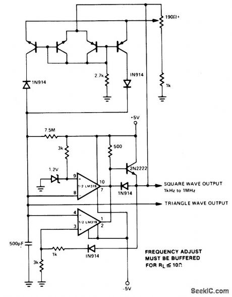
1_kHz_OSCILLATOR
Published:2009/7/5 22:57:00 Author:May
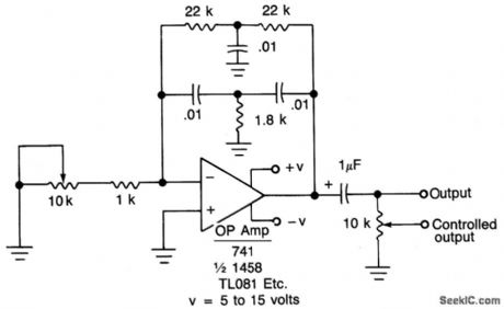
If fine output control is desired, add the 10 K potentiometer. When the oscillator is connected to a dc circuit then connect a dc blocking capacitor in series with the potentiometer's wiper arm. (View)
View full Circuit Diagram | Comments | Reading(1448)
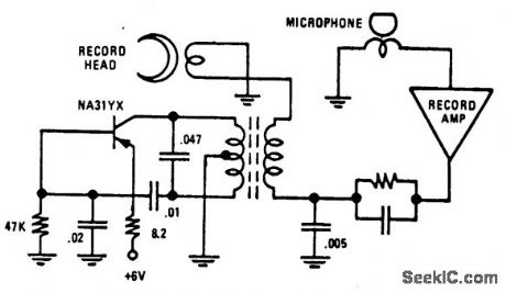
CASSETTE_BIAS_OSCILLATOR
Published:2009/7/5 22:55:00 Author:May
View full Circuit Diagram | Comments | Reading(720)
RESISTANCE_CONTROLLED_DIGITAL_OSCILLATOR
Published:2009/7/5 22:55:00 Author:May
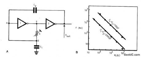
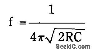
This very simple, low cost oscillator, is built with two CMOS buffer inverters, two capacitors and a variable resistance. The circuit can work with voltages ranging from 4 V up to 18 V. If C1 = C2, the frequency of oscillation, (ignoring the output and input impedance) is given by:
The graph in Fig. B shows how the output frequency varies with resistance when C1=C2=100 pF and C1=C2=2000 pF.
(View)
View full Circuit Diagram | Comments | Reading(778)
TUNABLE_FREQUENCY_OSCILLATORS
Published:2009/7/5 22:53:00 Author:May
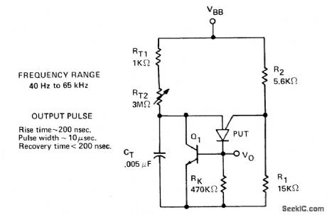
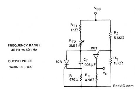
The variable oscillator circuit includes active elements for discharging the timing capacitor CT shown in Fig. 66-7A. A second method is given as in Fig. 66-7B (View)
View full Circuit Diagram | Comments | Reading(785)
| Pages:35/54 At 202122232425262728293031323334353637383940Under 20 |
Circuit Categories
power supply circuit
Amplifier Circuit
Basic Circuit
LED and Light Circuit
Sensor Circuit
Signal Processing
Electrical Equipment Circuit
Control Circuit
Remote Control Circuit
A/D-D/A Converter Circuit
Audio Circuit
Measuring and Test Circuit
Communication Circuit
Computer-Related Circuit
555 Circuit
Automotive Circuit
Repairing Circuit