
Oscillator Circuit
Index 36
SINGLE_CONTROL_FOUR_DECADE_VARIABLE_OSCILLATOR
Published:2009/7/5 22:52:00 Author:May
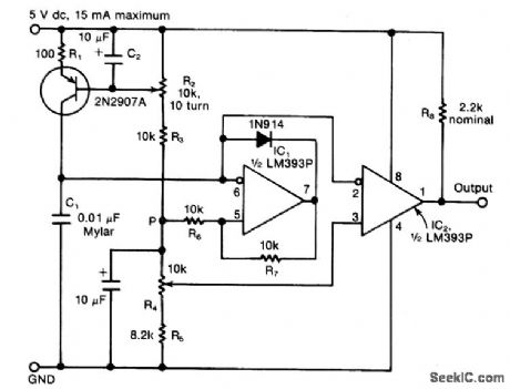
The circuit consists of a variable current Source that charges a capacitor, which is rapidly discharged by a Schmitt-trigger comparator, The sawtooth waveform thusproduced is fed to another comparator, one with a variable switching level. The outputfrom the second comparator is a pulse train with an independently adjustable frequencyand duty cycle. The variable-frequency ramp generator consists of capacitor C1, which is charged by a variable and nonlinear current source. The latter compnses a 2N2907A pnp transistor, plus resistor R1 and the potentiometer R2 Capacitor C2 eliminates any ripple or nolse at the base ofthe transistor that might cause frequency jitter at the output (View)
View full Circuit Diagram | Comments | Reading(1655)
4_MHz_NAND_GATE_OSCILLATOR_SYNCHRO_NIZES_TW0_MPUs_
Published:2009/7/5 22:50:00 Author:May
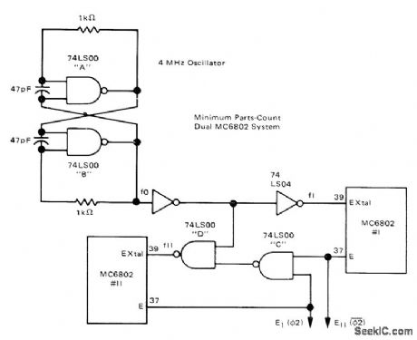
Low-cost NAND-gate sections A and B form low-cost oscillator for driving two Motorola MC6802 microprocessors.NAND gates C and D function as phase-locked loop, with D ensuring that phases of enable outputs are 180° apart. Small drifts in oscillator frequency do not affect synchronization. Circuit allows each MPU to operate during half-cycle that other MPU has disabled, to provide additional computing power of two microprocessors while maintaining system costs of onedata bus.-J. Farrell, Synchronizing Two Motorola MC6802s on One Bus, Motorola, Phoenix, AZ, 1978, AN-783. (View)
View full Circuit Diagram | Comments | Reading(1341)
ONE_SECOND,1_kHz_OSCILLATOR
Published:2009/7/5 22:49:00 Author:May
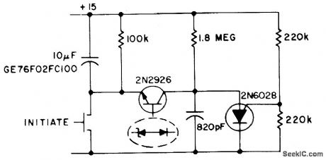
This circuit operates as an oscillator and a timer. The 2N6028 is normally on due to excess holding current through the 100 k resistor.
When the switch is momentarily closed, the 10 μF capacitor is charged to a full 15 volts and 2N2926 starts oscillating (1.8 M and 820 pF). (View)
View full Circuit Diagram | Comments | Reading(2338)
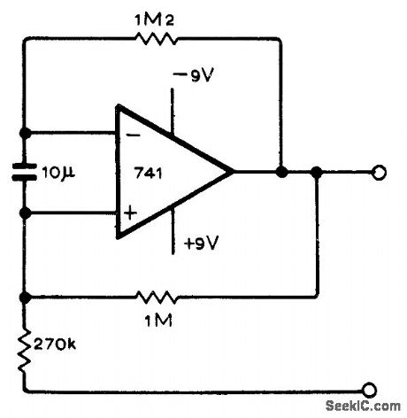
OSCILLATOR_ADJUSTABLE_OVER_10_1_RANGE
Published:2009/7/5 22:48:00 Author:May
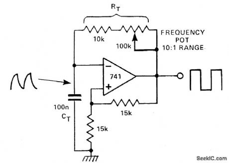
In this circuit, there are two feedback paths around an op amp. One is positive dc feedback which forms a Schmitt trigger. The other is a CR timing network. Imagine that the output voltage is +10V. The voltage at the noninverting terminal is +15V.
The voltage at the inverting terminal is a rising voltage with a time constant of CTRT.
When this voltage exceeds + 5V, the op amp's output will go low and the Schmitt trigger action will make it snap into its negative state. Now the output is - 10 V and the voltage at the inverting terminal falls with the time constant as before. By changing this time constant with a variable resistor, a variable frequency oscillation may be produced. (View)
View full Circuit Diagram | Comments | Reading(1443)
5_pF_TO_1μF
Published:2009/7/5 22:47:00 Author:May
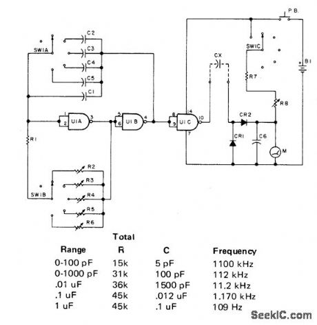
Consists of an oscillator using two gates from CD4011 quad NAND gate, separated from diode rectifier by another NAND gate. Increasing oscillator frequency gives more pulses per second and higher integrated meter reading. Each meter range is linear, so value of 5-pF capacitor can be read on lowest range.Diodes are 1N34 or equivalent. R1 is 12K, and R2-R6 are 50K trimpots set to values shown in table. R7 is 5K, and R8 is 10K trimpot. B1 is 9-V transistor battery. Article covers construction and calibration with known capacitors.-E. Landefeld, Build a Simple Capacitance Meter, 73Magazine, Jan. 1978, p 164-165. (View)
View full Circuit Diagram | Comments | Reading(1291)
EMITTER_COUPLED_BIG_LOOP_OSCILLATOR
Published:2009/7/5 22:45:00 Author:May
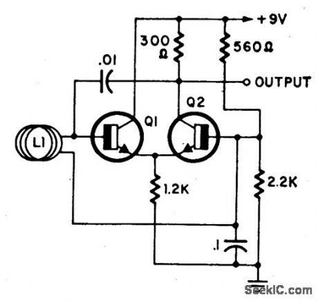
L1 is a loop of 10 to 20 turns of insulated wire with a diameter anywhere between 4 to 4'. Oscillator frequency (7 to 30 MHz) shifts substantially when a person comes near or into the loop. This oscillator together with a reso-nant detector might make a very good anti-personnel alarm. Transistors are 2N2926 or equivalent. (View)
View full Circuit Diagram | Comments | Reading(1028)
RF_GENIE
Published:2009/7/5 22:43:00 Author:May
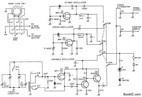
A variable oscillator covers 3.2 to 22 MHz in two bands-providing coverage of 80 through 15 meters plus most crystal-filter frequencies. Optional455 kHz and 10.7 MHz crystal oscillators can be switched on-line for precise tf alianmen' generator output is on the order of 4 volts p-p into a 500 ohm load. A simple voltage-divider attenuator controls the generator's output level, and a second output provides sufficient drive for an external frequency counter. (View)
View full Circuit Diagram | Comments | Reading(2282)
20_20000_Hz
Published:2009/7/5 22:42:00 Author:May
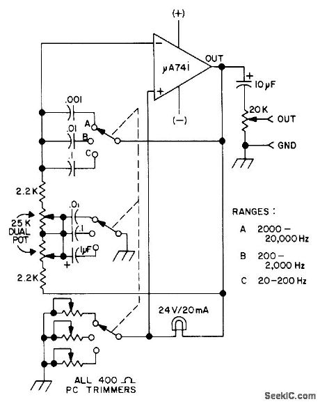
Wide-range audio oscillator covers AF spectrum in three switch-selected ranges, with harmonic distortion as low as 0.15%, for quick checks of audio equipment. Drain is only 6 mA from two 9-V batteries. Circuit is Wien-bridge oscillator using 741 opamp. Article covers construction and calibration, including optional connection for operation from single 9-V battery with AF output reduced to 2 V.-J. J. Schultz, Wide Range IC Audio Oscillator, 73 Magazine, Jan. 1974, p 25-28. (View)
View full Circuit Diagram | Comments | Reading(974)
DIGITAL_TRANSMISSION_ISOLATOR
Published:2009/7/5 22:32:00 Author:May
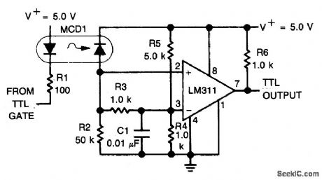
An optoelectronics device is used to couple a digital (TTL) signal to another system. The photodiode in the optocoupler drives an LM311 set up to produce a TTL compatible output. It is useful where grounds are not able to be connected for any reason. (View)
View full Circuit Diagram | Comments | Reading(0)
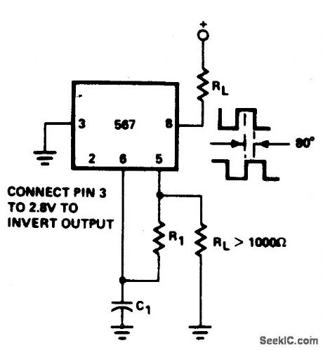
PRECISION_OSCILLATOR_TO_SWITCH_100_mA_LOADS
Published:2009/7/5 22:32:00 Author:May
View full Circuit Diagram | Comments | Reading(696)
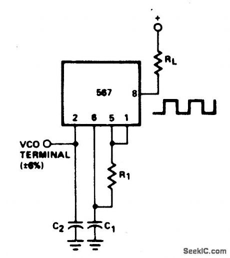
WIDE_RANGE_VARIABLE_OSCILLATOR
Published:2009/7/5 22:31:00 Author:May
View full Circuit Diagram | Comments | Reading(791)
OSCILIATOR_WITH_QUADRATURE_OUTPUT
Published:2009/7/5 22:30:00 Author:May
View full Circuit Diagram | Comments | Reading(773)
PRECISION_OSCILLATOR_WITH_20_NS_SWITCHING
Published:2009/7/5 22:30:00 Author:May
View full Circuit Diagram | Comments | Reading(744)
EXPONENTIAL_DIGITALLY_CONTROLLED_OSCILLATOR
Published:2009/7/5 22:27:00 Author:May


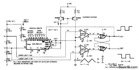
The microprocessor-controlled oscillator has a 8159 to 1 frequency range covering 2.5 Hz to 20 kHz. An exponential, current output IC DAC functioning as a programmable current source alternately charges and discharges capacitor between precisely-controlled upper and lower limits. The circuit features instan-taneous frequency change, operates with +5 ±1 V and -15 V ±3 V supplies, and has the dynamic range of a 13-bit DAC. (View)
View full Circuit Diagram | Comments | Reading(888)
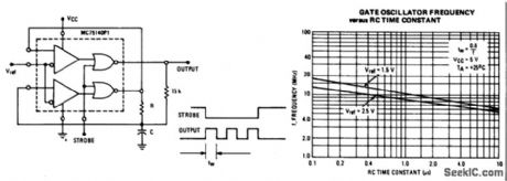
GATED_OSCILLATOR
Published:2009/7/5 22:24:00 Author:May
View full Circuit Diagram | Comments | Reading(0)
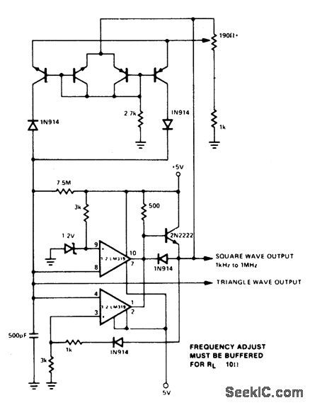
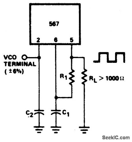
VARIABLE_AUDIO_OSCILLATOR,20_Hz_TO_20_kHz
Published:2009/7/5 22:23:00 Author:May
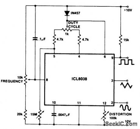
To obtain a 1000:1 Sweep Range, the vol-tage across external resistors RA and RB must decrease to nearly zero. This requires that the highest voltage on control pin 8 exceed the voltage at the top of RA and RB by a few hundred millivolts. The circuit achieves this by using a diode to lower the effective supply voltage on the 8038. The large resistor on pin 5 helps reduce duty cycle variations with sweep. (View)
View full Circuit Diagram | Comments | Reading(971)
50_kHz_OSCILLATOR
Published:2009/7/5 22:21:00 Author:May

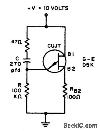
A 50 kHz circuit is possible becasuse of the more nearly ideal characteristics of the D5K. (View)
View full Circuit Diagram | Comments | Reading(1072)
10_kHz_OSCILLATOR
Published:2009/7/5 22:20:00 Author:May
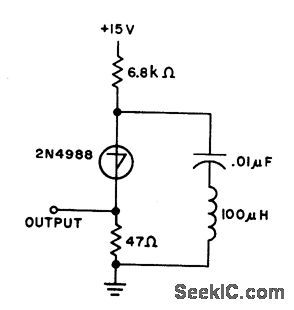
The capacitor charges until switching vol-tage is reached. When SUS switches on, the inductor causes current to ring. When the cur-rent thru SUS drops below the holding current, the device turns off and the cycle repeats. (View)
View full Circuit Diagram | Comments | Reading(824)
38_kHz
Published:2009/7/5 21:40:00 Author:May
Simple opamp circuit provides convenient sine-wave AF signal.-J. s. Lucas. Unusual Sinewave Generator.Wireless World. May 1977.p 81 (View)
View full Circuit Diagram | Comments | Reading(2833)
CRYSTAL_DISCRIMINATOR_
Published:2009/7/4 4:00:00 Author:May
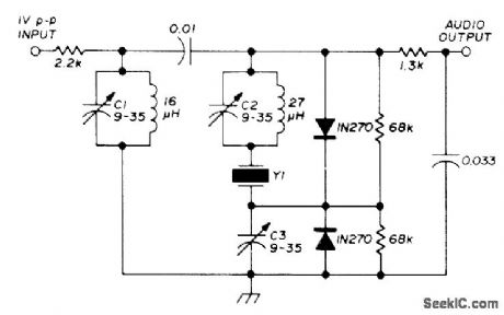
Inexpen sive third-overtone CB crystal used at 9-MHz fundamental serves as high-performance discriminator for VHF FM receiver. Adjust C3 for zero voltage with unmodulated carrier at or near center frequency. Adjust CI and C2 with AF sine wave applied to FM signal generator, using CR0 to check distortion of recovered sinewave. With 1 V P-P IF signal at 9 MHz and 5-kHz deviation, recovered audio will be about 1 V P-P at lower audio frequencies. Good limiter is required ahead of discriminator for AM rejection.-G. K.Shubert, Crystal Discriminator for VHF FM, Ham Radio, Oct. 1975, p 67-69. (View)
View full Circuit Diagram | Comments | Reading(2621)
| Pages:36/54 At 202122232425262728293031323334353637383940Under 20 |
Circuit Categories
power supply circuit
Amplifier Circuit
Basic Circuit
LED and Light Circuit
Sensor Circuit
Signal Processing
Electrical Equipment Circuit
Control Circuit
Remote Control Circuit
A/D-D/A Converter Circuit
Audio Circuit
Measuring and Test Circuit
Communication Circuit
Computer-Related Circuit
555 Circuit
Automotive Circuit
Repairing Circuit