
A/D-D/A Converter Circuit
Index 23
DIGITAL_TO_ANALOG_CONVERTER
Published:2009/6/17 3:56:00 Author:May
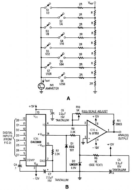

Figure A is an R/2R resistor ladder. Each switch that is closed increases the amount of current at Iout. A simple channel A/D converter is shown in Fig. B. The voltage reference (D2) is common to all channels, but the value of the dropping resistor (R9) varies as the number of DACs installed in the system. IC15 is a DAC0808 A/D converter chip. IC16A is an op amp to interface the output current from the D/A convert to an analog voltage output. (View)
View full Circuit Diagram | Comments | Reading(1169)
SIMPLE_WWV_CONVERTER_FOR_AUTO_RADIOS
Published:2009/6/17 3:54:00 Author:May
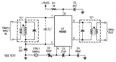
This simple frequency converter mixes the 15-MHz WWV/WVH signal with a 16-MHz signal from the LO to convert it down to 1 MHz so that it can be heard on AM-band receiver. (View)
View full Circuit Diagram | Comments | Reading(922)
3_A_dc_dc_CONVERTER_NEEDS_NO_HEATSINK
Published:2009/6/17 3:53:00 Author:May
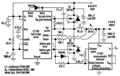
This regulator delivers 90% efficiency at 12-V input, 5-V output. It uses an LT1158 and LT1431 by Linear Technology, Inc. High efficiency is obtained by synchronously switching two power MOS-FETs in a step-down switching regulator. The LT1431 voltage reference combines with the LT1158 half-bridge driver to form a constant off-time current mode loop. (View)
View full Circuit Diagram | Comments | Reading(1519)
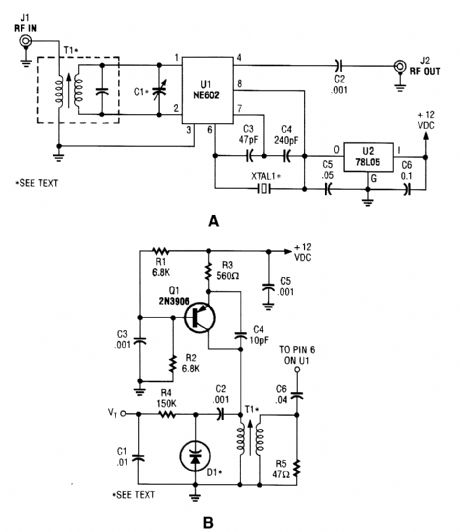
HIGH_PERFORMANCE_SHORTWAVE_CONVERTER
Published:2009/6/17 3:48:00 Author:May
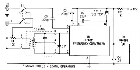
The NE602 chip, U1, contains oscillator and mixer stages. The mixer combines the oscillator sig-nal with the input RE signal to produce signals whose frequencies are the sum and difference of the input frequencies. For example, an 8.5-MHz oscillator and a 10-MHz incoming signal will give output signals at 18.5 MHz (10 + 8.5) and 1.5 MHz (10 - 8.5). Recall that 1.5 MHz is 1500 kHz and an ordinary AM radio will tune to it.The choice of crystal depends on what shortwave band you want to hear. The 9.5- to 10-MHz band is less crowded and includes the time-signal station WWW. For that band, you'll need a crystal of 8.5 to 8.9 MHz. There is no standard microprocessor crystal in that range, but you can use an am-ateur radio crystal, have a crystal custom-made, or use a CB crystal.Transformer T1 rejects signals that are outside the band you are interested in. Transformer T1 should pass signals from 9 to 11 MHz and attenuate all others. The transformer, T1, used in the circuit is a 10.7-MHz IF transformer salvaged from an FM radio.They are fairly easy to obtain new from parts stores and mail-order houses. Most 10.7-MHz IF trans-formers will tune across the 9.5- to 10-MHz band without modification; all you need to do is turn its tuning slug. To receive the 6.0- to 6.5-MHz shortwave band, you'll have to add a 150-pF capacitor. (View)
View full Circuit Diagram | Comments | Reading(1541)
ONE_CHIP_CRYSTAL_CONTROLLED_CONVERTER
Published:2009/6/17 3:42:00 Author:May
The circuit can work over a wide range of frequencies. XTAL 1 is a fundamental-frequency crystal. T1 and C1 are tuned to the input frequency. An application of this circuit is a simple shortwave converter for AM radios, etc. A tuneable oscillator can also be used, as shown. (View)
View full Circuit Diagram | Comments | Reading(1040)
250_W_INVERTER
Published:2009/6/16 23:27:00 Author:May
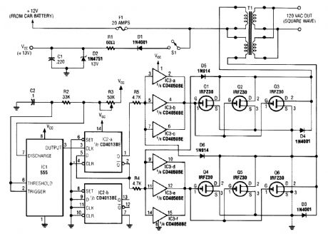
A 555 timer (IC1) generates a 120-Hz signal that is fed to a CD4013BE flip-flop (IC1-a), which divides the input frequency by two to generate a 60-Hz clocking frequency for the FET array (Q1 through Q6). Transformer T1 is a 12-/24-V center-tapped 60-Hz transformer of suitable size. (View)
View full Circuit Diagram | Comments | Reading(3592)
IR_PULSE_TO_AUDIO_CONVERTER
Published:2009/6/16 22:06:00 Author:May
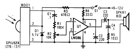
If your ear is good, you can use this IR-pulse-to-audio converter to troubleshoot infrared remote-controts. It is also a good project for detecting infrared-light sources. A photo cell module (Radio Shack P/N 276-137) detects IR radiation and drives audio IC U1. This circuit is useful for trou-bleshooting IR remote controls. (View)
View full Circuit Diagram | Comments | Reading(1178)
8_CHANNEL_A_D_CONVERTER_FOR_PC_CLONESCont
Published:2009/6/15 4:18:00 Author:May
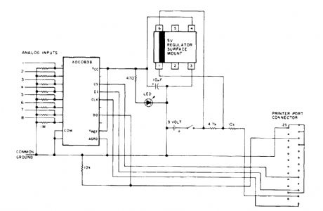
An A/D converter by National Semiconductor(ADC0838),converts 0- to 5-V analog inputs to adigital data format A 9-V battery is used.The converter connects to the pointer port connector viaa 25-pin connector (View)
View full Circuit Diagram | Comments | Reading(1619)
ADO_POLLER
Published:2009/6/15 4:15:00 Author:May
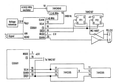
Because the CS5501 16-bit-delta-sigma analog-to-digital converter lacks a start convert com-mand, it converts continuously, outputting conversion words to its output register every 1024 cycles of its master clock. However, by incorporating a standard dual J-K flip-flop into the circuit, the ADC can be configured to output a single-conversion word only when it is polled.The CS5501 converter can be operated in its asynchronous communication mode (UART) to transmit one 16-bit conversion word when it is polled over an RS-232 serial line (see figure). A null character (all zeros) is transmitted to the circuit and sets the flip-flop FE2. The CS5501 can then out-put a single-conversion word, which is transmitted over the RS-232 line as two bytes with start and stop bits.The baud rate can be chosen by selecting the appropriate clock divider rate on the 74HC4040 counter/divider as the serial port clock (SLCK) for the ADC. This type of polled-mode operation is also useful when the ADC's output register is configured to operate in the synchronous-serial clock (SSC) mode. In this case, the converter will load one output word into a 16-bit serial-to-parallel reg-ister (two 74HC595 8-bit registers) when polled to do so (see figure). (View)
View full Circuit Diagram | Comments | Reading(1335)
ADC1210/1211 12 bit A/D converter
Published:2011/7/17 20:57:00 Author:zj | Keyword: 12 bit, A/D converter
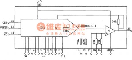
ADC1210/1211 is low power, medium speed 12 bit successive approximation type CMOS package A/D converter. The reference voltage is supplied by external power supply. It can work with single or dual power. Analog input can be monopole or bipolar. Analog input impedanceis 200K ohm. The internal circuit diagram is as shown in the figure. (View)
View full Circuit Diagram | Comments | Reading(813)
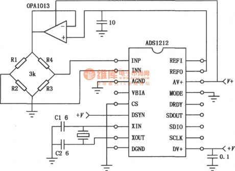
ADS1212 22 bit A/D converter measurement application circuit
Published:2011/7/17 22:14:00 Author:zj | Keyword: 22 bit A/D converter, measurement application circuit
View full Circuit Diagram | Comments | Reading(1067)
Self-made high power and high efficiency inverted module circuit
Published:2011/7/20 23:51:00 Author:leo | Keyword: High power, high efficiency, inverted module

View full Circuit Diagram | Comments | Reading(1096)
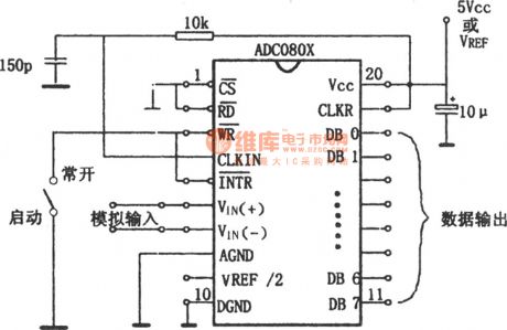
Self-excitation A/D converter circuit composed of ADC0801~0805
Published:2011/7/20 2:39:00 Author:zj | Keyword: Self-excitation, A/D converter circuit
View full Circuit Diagram | Comments | Reading(1697)
Band conversion circuit composed of LA7910
Published:2011/7/20 2:51:00 Author:zj | Keyword: Band conversion circuit
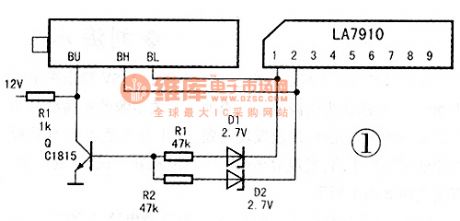
View full Circuit Diagram | Comments | Reading(3124)
CS4338K audio D/A transformation integrated circuit diagram
Published:2011/5/9 9:03:00 Author:Nicole | Keyword: audio, D/A transformation
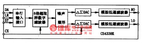
CS4338K is a two-channel D/A transformation integrated circuit with 2Obit resolution which is produced by crystal company, it is widely used in DVD player.
CS4338K integrated circuit contains 8 times sampled digital filter, noise shaping circuit and chip load simulation low pass filter circuit. It is used to change the digit audio singal into analogue audio signal. The internal circuit block diagram of this integrated block is shown as figure1.
Figure1, the internal circuit block diagram of CS4338K integrated block is shown.
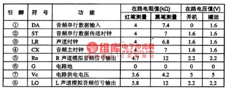
CS4338K integrated circuit adopts 8-foot dual in-line package, the pin function and data of this integrated circuit is shown in chart1.
Chart1 the pin function and data of CS4338K integrated circuit is shown. (View)
View full Circuit Diagram | Comments | Reading(712)
50W DC converter
Published:2011/7/15 23:53:00 Author:Christina | Keyword: 50W, DC, converter
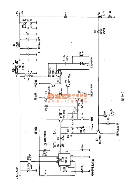
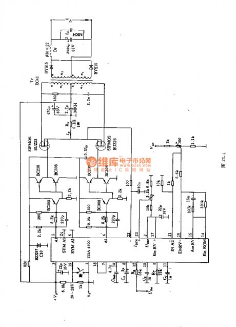
The control, adjustment, surveillance, and other functions are beared by the TDA4700, the output controls the push-pull stage, and the voltage is output by the transformer.
The main technical data:
Output voltage U1:20-28V(typical value:24V)Output voltage U2:0-5.25V(typical value:5V)Output current I2:0-10ALoad voltage adjustment rate:0.4%efficiency:72%Positive loss PVD:0.9WSwitch loss PVS=0.4WTotal loss PVD+PVS=1.3W.
(View)
View full Circuit Diagram | Comments | Reading(1002)
SAA3028 infrared remote control code conversion circuit
Published:2011/7/12 7:01:00 Author:Christina | Keyword: infrared, remote control, code, conversion
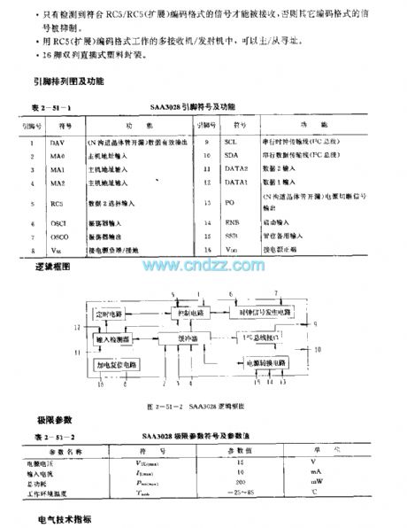
The SAA3028 is designed as one kind of general infrared remote control code conversion circuit, the main function of it is to change the RC5/RC5 duplex encoded signal into the equivalent binary code.
Features
The power conversion is convenient; Use the power up reset to start it;The data outputs and inputs by the serial transmission mode, the output port is compatible with the I2C bus;It has two data input ports. One of them can only input the RC5 coded signal, another one can only receive the RC5 coded signal or the RC5 number signal;It only receives the signal which meets the RC5/RC5 encoding format;It is in the 16-pin dual-row DIP plastic package.
(View)
View full Circuit Diagram | Comments | Reading(793)
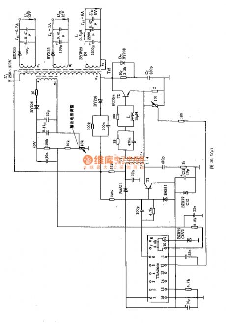
MOSFET resonance type DC-DC converter circuit
Published:2011/7/12 4:58:00 Author:TaoXi | Keyword: MOSFET, resonance type, DC-DC, converter
The MOSFET resonance type DC-DC converter circuit is as shown in the figure. The Los ella circuit is working through the transformer magnetic saturation and transistor flip overturn. In this circuit, the transformer is operating in the unsaturated mode, it presents the arc-shaped change through the gate feedback voltage of the MOSFET, and it everts the MOSFET by reducing gate voltage.
This AC flows through the transformer primary coil Np. The transformer primary coil and the capacitance C1 produce the reverse-polarity resonance current. The oscillation frequency f of this circuit is decided by the resonant frequencies of the inductance Lp and the capacitor C1 of the transformer primary coil:1/[2π*(Lp*c1)1/2]. (View)
View full Circuit Diagram | Comments | Reading(4481)
300kHz 600W ZVT--PWM boost converter
Published:2011/7/12 20:55:00 Author:TaoXi | Keyword: 300kHz, 600W, ZVT--PWM, boost converter
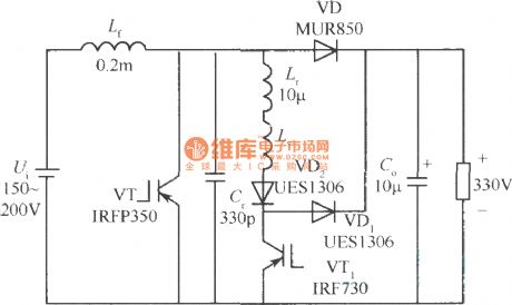
The power stage circuit is as shown in the figure, you can design the switching voltage stabilization power supply with the 300kHz switching frequency, 600W output power and 300V output voltage by using the ZVT--PWM boost converter. The input voltage is 150~200V.
The Ls is the saturable reactor, it can be used to eliminate the ringing between the Lr and the VT1 output capacitance, it uses the Toshiba spike killer SAl0×6×4.5 magnetic core, the circle number is five. You can use the rapid recovery diode VD2 to stop the conduction of the VTl ontology diode. If there is no diode, the VTl will conduct the current to supply power to the resonance between the Lr and the VTl output capacitance. So when the VT1 is closing, it will bear the reverse recovery problem.
(View)
View full Circuit Diagram | Comments | Reading(2163)
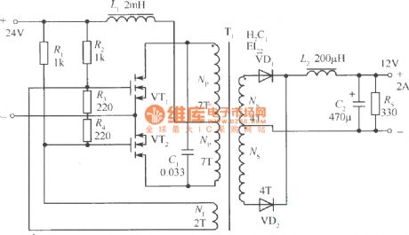
Rate associated push-pull voltage converter circuit
Published:2011/7/10 18:54:00 Author:TaoXi | Keyword: Rate associated, push-pull, voltage converter
Figure:Rate associated push-pull voltage converter circuit
(View)
View full Circuit Diagram | Comments | Reading(758)
| Pages:23/24 At 2021222324 |
Circuit Categories
power supply circuit
Amplifier Circuit
Basic Circuit
LED and Light Circuit
Sensor Circuit
Signal Processing
Electrical Equipment Circuit
Control Circuit
Remote Control Circuit
A/D-D/A Converter Circuit
Audio Circuit
Measuring and Test Circuit
Communication Circuit
Computer-Related Circuit
555 Circuit
Automotive Circuit
Repairing Circuit