
Filter Circuit
Index 10
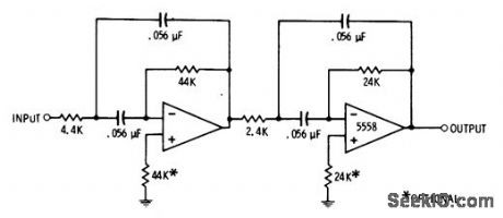
800_Hz_BANDPASS
Published:2009/7/3 2:24:00 Author:May
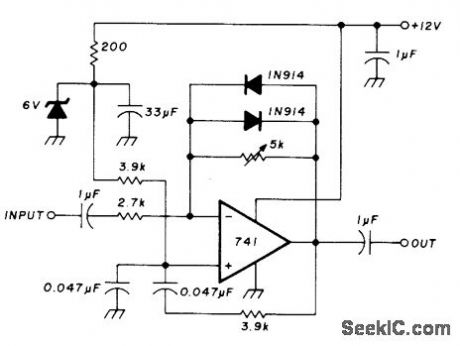
Active filter has 800-Hz center frequency for optimum CW reception.Bandwidth is adjustable. Back-to-back diodes provide noise-limiting capability.-U. L. Rohde, IF Amplifier Design, Ham Radio, March 1977, p 10-21. (View)
View full Circuit Diagram | Comments | Reading(1119)
AF_LOW_PASS_FOR_CW
Published:2009/7/3 2:20:00 Author:May
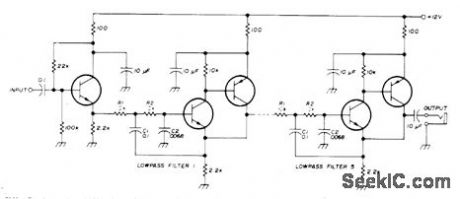
Design using 10% tolerance components gives sufficiently wide bandwidth while maintaining steep skirt re sponse for CW reception in direct-conversion communication receiver. Filter has five identical three-transistor sections, each peaked at cutoff frequency. a of each section is about 1.9, which gives 6-dB bandwidth of about 200 Hz. With center frequency at 540 Hz attenuation is 75 dB at 1200 Hz. Net gain of system is 28 dB at resonance. NPN transistors are 2N3565,2N3904, or similar; PNP transistors are 2N3638, 2N3906, or similar.-W. Howard, Simple Active Filters for Direct-Conversion Receivers, Ham Radio, April 1974, p 12-15. (View)
View full Circuit Diagram | Comments | Reading(1100)
TUNABLE_FOURTH_ORDER_LOW_PASS
Published:2009/7/3 2:19:00 Author:May
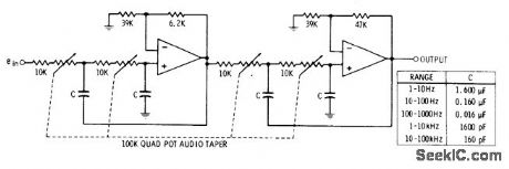
Use of four ganged pots permits varying cutoff frequency over 10:1 range. Table gives ranges obtainable with five different values for C.Opamps can be 741 or equivalent. Tracking of 5% for pots calls for expensive components, but ordinary snap-together pots may prove satisfactory if tuning range is restricted to 3:1 or less and more capacitor switching is used.-D. Lancas.ter, Active-Filter Cookbook, Howard W.Sams,Indianapolis, IN, 1975, p 195-197. (View)
View full Circuit Diagram | Comments | Reading(867)
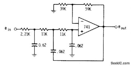
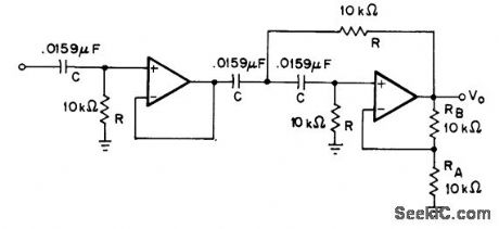
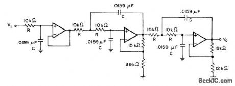
24_kHz_LOW_PASS_HIGH_PASS
Published:2009/7/3 2:18:00 Author:May
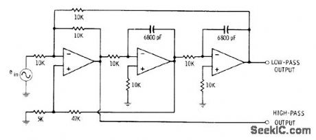
Three 741 opamps are connected toprovide separate low-pass and high-pass outputs simultaneously for complex synthesis problem requirIng state-variable filter Gain is 1.-D,Lancaster, Active-Filter Cookbook, Howard W,Sams,Indianapolis,IN,1975, p 192-193. (View)
View full Circuit Diagram | Comments | Reading(888)
200_400_Hz_PASSBAND
Published:2009/7/2 23:39:00 Author:May
Design is based on use of 3.2 for value of Q, to hold passband dip at 1 dB for two-pole filter. Multiple feedback is used for each pole. First opamp can be 741 or equivalent. Centerfrequency is 283 Hz.-D. Lancaster, Active-Filter Cookbook, Howard W.Sams, Indianapolis, IN, 1975, p 166. (View)
View full Circuit Diagram | Comments | Reading(957)
250_Hz_THIRD_ORDER_LOW_PASS
Published:2009/7/2 23:38:00 Author:May
Values shown place cutoff at 250 Hz, with 1-dB dip in response curve. Input must be returned to ground with low-impedance DC path.-D. Lan-caster, Active-Filter Cookbook, Howard W.Sams, Indianapolis, IN, 1975, p 146. (View)
View full Circuit Diagram | Comments | Reading(851)
20_2000Hz_VARIABLE_BANDPASS
Published:2009/7/2 23:24:00 Author:May
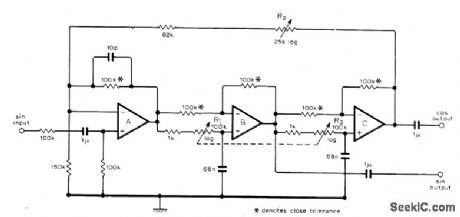
High-Q active bandpass filter can be adjusted over wide frequency range (100:1) while maintaining Q essentially constant over 100. Two-phase output is available. Opamps can be 741 or equivalent. Cascaded all-pass networks B and C each have 0 to 180° phase variation and unity gain at all frequencies, These are driven by opamp A whose feedback signal is sum of input and output of all-pass networks.R2 adjusts Q,andganged log pots change center frequency,-J.M.worley,Variable Band-Pass Filter, Wireless World,April 1977,p 61. (View)
View full Circuit Diagram | Comments | Reading(1094)
1_kHz_THIRD_ORDER_HIGH_PASS
Published:2009/7/2 23:22:00 Author:May
Passband gain is 6 dB for Butter worth filter above 1-kHz cutoff Damping factor is 1.000 for both sections,each using 741 or equivalent opamp,-H.M.Berin, Design of Active Filters,with Experiments, Howard w. Sams, Indianapolis, IN,1977,p 115-116. (View)
View full Circuit Diagram | Comments | Reading(999)
1_kHz_BIQUAD_BANDPASS
Published:2009/7/2 23:18:00 Author:May
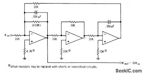
Three 741 opamps are connected to give two integrators and inverter. Overall gain is -Q, determined by value of input resistor used. Circuit is tuned by varying capacitors in steps. Absolute bandwidth remains constant asfrequency changes. Chief applications are in telephone systems, where identical absolute-bandwidth channels are required.-D. Lancaster, Active-Filter Cookbook, Howard W. Sams, Indianapolis, IN, 1975, p 159-164. (View)
View full Circuit Diagram | Comments | Reading(908)
1_kHz_THIRD_ORDER_LOW_PASS
Published:2009/7/2 23:17:00 Author:May
Circuit using 741 or equivalent opamp consists of unity-gain first-order section followed by equal-component voltage-controlled voltage-source secondorder section.-H. M. Berlin, Design of Active Filters, with Experiments, Howard W. Sams, Indianapolis, IN, 1977, p 113-114. (View)
View full Circuit Diagram | Comments | Reading(921)
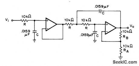
VOLTAGE_TUNED_STATE_VARIABLE
Published:2009/7/2 23:16:00 Author:May
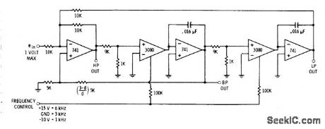

Provides choice of high-pass, bandpass, and low-pass outputs, each with cutoff frequency variable between 1 and 6 kHz by varying control voltage between -10 V and +15 V,Output load resistor sets voltage gain between input and output. Gain-control input varies gain from maximum set by load resistor down to zero.Input signals must be limited to 100 mV because input circuit is differential amplifier operating without feedback.-D. Lancaster, Active-Filter Cookbook, Howard W. Sams, Indianapolis, IN, 1975, p 203-205. (View)
View full Circuit Diagram | Comments | Reading(872)
320_Hz_LOW_PASS
Published:2009/7/2 23:14:00 Author:May
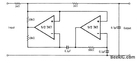
Frequency dependent negative-resistance circuit uses 747 dual opamp, Signal source used as input should have low resistance, and load should have high resistance. Voltage-follower stages can be used to isolate both input and output of filter.-R.Melen and H. Garland, Understanding IC Operational Amplifiers, Howard W. Sams, Indianapolis, IN, 2nd Ed.,1978, p 104-105. (View)
View full Circuit Diagram | Comments | Reading(692)
SPEECH_RECOGNITION_FILTER
Published:2009/7/2 22:07:00 Author:May
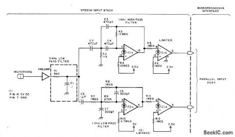
Voice signal picked up by microphone is preamplified and sent through 3-kHz low-pass passive filter C1-R1 to 1-kHz high-pass active filter and 1-kHz low-pass active filter using sections of LM3900 quad opamp. Diode symbols on opamps indicate use of current mirrors for noninverting inputs. Outputs are sampled about 60 times per second to implement speech recognition algorithm of computer, which counts number of high-pass and low-pass zero crossings per second and compares results with series of word models in memory to determine most likely match.-J. R. Boddie, Speech Recognition for a Personal Computer System, BYTE, July 1977, p 64-68 and 70-71. (View)
View full Circuit Diagram | Comments | Reading(2530)
1_kHz_FIFTH_ORDER_LOW_PASS
Published:2009/7/2 22:06:00 Author:May
Uses single first-order section and two different second-order sections to give passband gain of 10.3 dB,Opamps can be 741 or equlvalent,-H,M.Berlin, Design of Active Filters, with Experments, Howard W,Sams, Indianapons, IN,1977,p 119-122. (View)
View full Circuit Diagram | Comments | Reading(1085)
TUNABLE_NOTCH_FILTER
Published:2009/7/2 22:03:00 Author:May
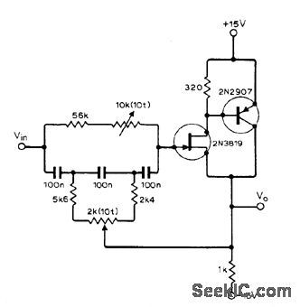
Simple pot-tuned active notch filter has tuning range of 200 Hz in audio band and 3-dB rejection bandwidth of 10 Hz, as required for tuning out whistle or powerline hum that is interfering with radio program.Article gives design theory for many other types of notch filters.-Y. Nezer, Activ (View)
View full Circuit Diagram | Comments | Reading(0)
CLOCK_FOR_COMMUTATING_RC_FILTER
Published:2009/7/2 21:22:00 Author:May
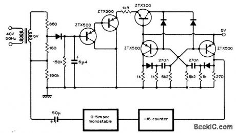
Circuit synchronizes multivibrator with line frequency to provide dock waveform required for switching capacitors electronically in npath active filter for rejecting line frequency and harmonics up to fifth. Article gives complete circuit of active filter and describes operation. Clock serves to switch 16 MOSFETs on in turn for commutating 16 capacitors electronically at 16 times line frequency.-K. F. Knott and L. Unsworth, Mains Rejection Tracking Filter, Wireless World, Oct. 1974, p 375-379. (View)
View full Circuit Diagram | Comments | Reading(766)
1_Hz_BANDPASS
Published:2009/7/2 21:13:00 Author:May
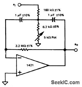
Single pot provides easy trimming to exact center frequency desired without change in bandwidth or gain. Q is 10.Design equations are given.-R. A. Pease, Band-Pass Active Filter with Easy Trim for Center Frequency, Teledyne PhilbHck, Dedham, MA, 1972, Applications Bulletin 4. (View)
View full Circuit Diagram | Comments | Reading(857)
1_kHz_BANDPASS_1
Published:2009/7/2 21:11:00 Author:May

Simple circuit using voltage-fonower opamp provbides bandpass of 1 kHz centered on 1 kHz,to give outputrange of 500-1500 Hz.- The Linear and Interface Circuits Data Book for Design Engineers, Texas Instruments, Dallas, TX, 1973, p 4-39. (View)
View full Circuit Diagram | Comments | Reading(656)
1_kHz_BANDPASS
Published:2009/7/2 21:11:00 Author:May
Simple circuit using voltage-fonower opamp provbides bandpass of 1 kHz centered on 1 kHz,to give outputrange of 500-1500 Hz.- The Linear and Interface Circuits Data Book for Design Engineers, Texas Instruments, Dallas, TX, 1973, p 4-39. (View)
View full Circuit Diagram | Comments | Reading(776)
1_MHz_TRACKING_FILTER
Published:2009/7/2 20:38:00 Author:May
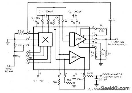
Exar XR-S200 PLLIC is connected to function as frequency filter when phase-locked loop locks on input signal, to produce filtered version of input signal frequency at VCO output. Because circuit can track input over 3:1 range of frequencies around freerunning frequency of VCO, it is known as tracking filter. Optional wideband discriminator output is also provided.- Phase-Locked Loop Data Book, Exar Integrated Systems, Sunnyvale,CA,1978, p 9-16. (View)
View full Circuit Diagram | Comments | Reading(891)
| Pages:10/21 1234567891011121314151617181920Under 20 |
Circuit Categories
power supply circuit
Amplifier Circuit
Basic Circuit
LED and Light Circuit
Sensor Circuit
Signal Processing
Electrical Equipment Circuit
Control Circuit
Remote Control Circuit
A/D-D/A Converter Circuit
Audio Circuit
Measuring and Test Circuit
Communication Circuit
Computer-Related Circuit
555 Circuit
Automotive Circuit
Repairing Circuit