
Filter Circuit
Index 14
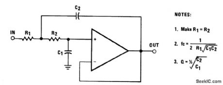
SALLEN_KEY_SECOND_ORDER_LOW_PASS_FILTER
Published:2009/6/29 21:47:00 Author:May
View full Circuit Diagram | Comments | Reading(714)
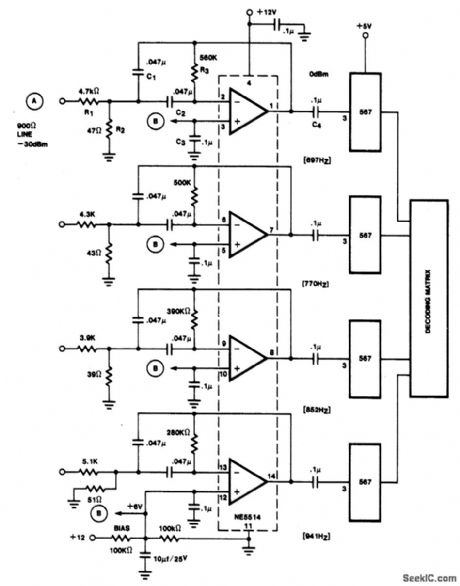
MFB_BANDPASS_FILTER_FOR_MULTICHANNEL_TONE_DECODER
Published:2009/6/29 21:44:00 Author:May
View full Circuit Diagram | Comments | Reading(733)
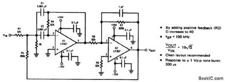
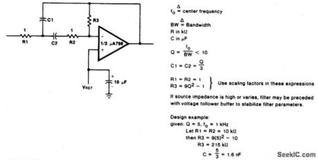
HIGH_Q_BANDPASS_FILTER
Published:2009/6/29 21:41:00 Author:May
View full Circuit Diagram | Comments | Reading(0)
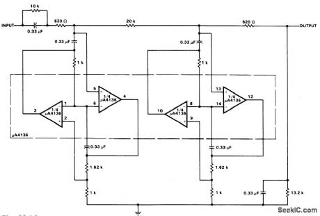
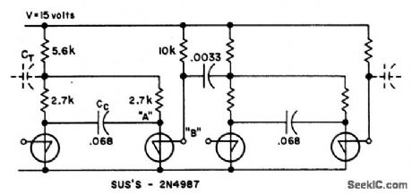
LOW_PASS_FILTER
Published:2009/6/29 21:40:00 Author:May
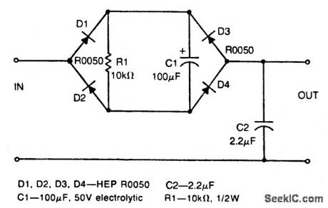
Circuit Notes
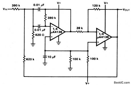
This nonlinear, passive filter circuit rejects ripple (or unwanted but fairly steady voltage) without appreciably affecting the rise time of a signal. The circuit works best when the signal level is considerably lower than the unwanted ripple, provided the ripple level is fairly constant. The circuit has characteristics similar to two peakdetecting sample-and-hold circuits in tandem with a voltage averager. (View)
View full Circuit Diagram | Comments | Reading(131)
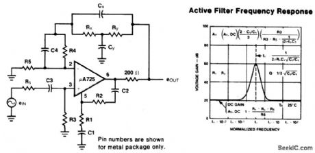
VARIABLE_BANDWIDTH_BANDPASS_ACTIVE_FILTER
Published:2009/6/29 21:36:00 Author:May

Circuit Notes
This circuit has adjustable bandwidthwith values for a center frequency of about 800 Hz. The10 K pot adjusts bandwidth from approximately ±350 Hz to ±140 Hz at 3 dB down points. (View)
View full Circuit Diagram | Comments | Reading(824)
400_Hz_LOW_PASS_BUTTERWORTH_ACTIVE_FILTER
Published:2009/6/29 21:34:00 Author:May
View full Circuit Diagram | Comments | Reading(622)
BIQUAD_RC_ACTIVE_BANDPASS_FILTER
Published:2009/6/29 21:30:00 Author:May
View full Circuit Diagram | Comments | Reading(841)
MULTIPLE_FEEDBACK_BANDPASS_FILTER
Published:2009/6/29 21:28:00 Author:May
View full Circuit Diagram | Comments | Reading(0)
BANDPASS_ACTIVE_FILTER_WITH_60_dB_GAIN
Published:2009/6/29 21:27:00 Author:May
View full Circuit Diagram | Comments | Reading(854)
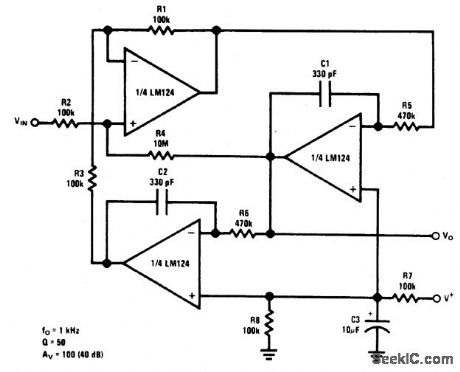
1_kHz_BANDPASS_ACTIVE_FILTER
Published:2009/6/29 21:25:00 Author:May
View full Circuit Diagram | Comments | Reading(668)
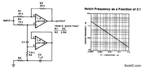
NOTCH_FILTER_USING_THE_μA4136_AS_A_GYRATOR
Published:2009/6/29 21:08:00 Author:May
View full Circuit Diagram | Comments | Reading(832)
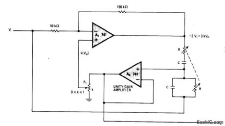
REJECTION_FILTER
Published:2009/6/29 21:07:00 Author:May
Circuit Notes
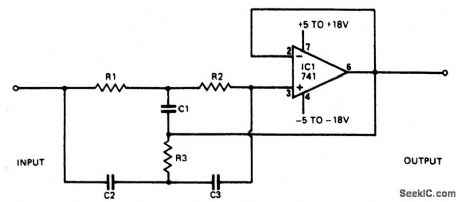
This narrowband filter using the 741 operational amplifier can provide up to 60 dB of rejection. With resistors equal to 100 K and capacitors equal to 320 pF, the circuit will reject 50 Hz. Frequencies within the 1 Hz to 10 kHz may be rejected by selecting components h accordance with the formula∶F=1/2πRCTo obtain rejections better than 40 dB,reslstors should be matched to 0.1%and capacitors to 1%. (View)
View full Circuit Diagram | Comments | Reading(882)
HIGH_Q_NOTCH_FILTER
Published:2009/6/29 20:58:00 Author:May

Circuit NotesA shows atwin-T network connected to anLM102 to form a high Q, 60 Hz notch filter, Thejunction of R3 and C3, which t normally connected to ground, is bootstrapped to the outputof the follower, Because the output of the follower is a very low impedance, neither the depth nor the frequency of then.tch change; however, the Q is raised In proportion to thealηount of signal fed back to R3 and C3. Bshows the response ofa normal twin-T and theresponse with the foilower added. (View)
View full Circuit Diagram | Comments | Reading(0)
45_MHz_NOTCH_FILTER_
Published:2009/6/29 20:56:00 Author:May
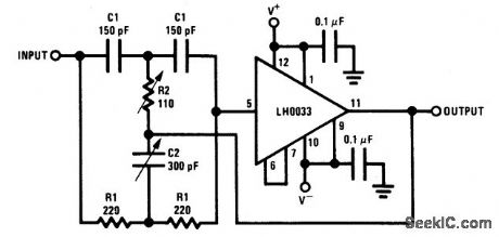
Circuit NotesComponenc value sensitivity is extremely critical, as are temperature coefficients and matching ofthe components. Best performa,ce is attained when perfectly matched components are used and when the gain of the amplifier is unity.To illustrate,the quality factor Q is very high as amplifier gam approaches1 with all components matched(In fact,theoretically it approaches co)but decreases toabout 12.5 with the amplifier gain at 0.98. (View)
View full Circuit Diagram | Comments | Reading(709)
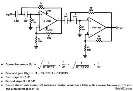
FOURTH_ORDER_HIGH_PASS_BUTTERWORTH_FILTER
Published:2009/6/29 4:38:00 Author:May
View full Circuit Diagram | Comments | Reading(0)
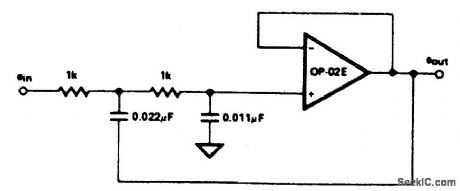
10_kHz_SALLEN_KEY_LOW_PASS_FILTER
Published:2009/6/29 4:36:00 Author:May
View full Circuit Diagram | Comments | Reading(701)
DIGITALLY_TUNED_LOW_POWER_ACTIVE_FILTER
Published:2009/6/29 4:35:00 Author:May
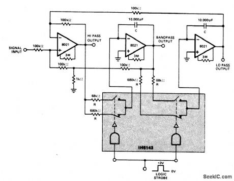
Circuit NotesConstant gain, constant Q, variable frequency filter which provides simultaneous low-pass, bandpass, and high-pass outputs.With the component values shown, center frequency will be 235 Hz and 23.5 Hz for high and low logic inputs respectively, Q=100, and gain=100.
fn=center frequency =1/2πRC (View)
View full Circuit Diagram | Comments | Reading(782)
FIVE_POLE_ACTIVE_FILTER
Published:2009/6/29 4:30:00 Author:May
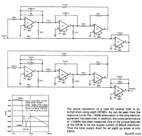
The above realization of a type D3 receive filter is accompished using eight OP-08's. As can be seen from 1he response curve the >30dB attenuation in the stop band re-qu jrement has been met. In addition, thenoise performance of <0dBHn has been measured. One of the unique features of the OP-08 is ils low supply current of 600μA maximum Thus the total supply dralrl for all eight op amps is only 4.8mA. (View)
View full Circuit Diagram | Comments | Reading(707)
SELECTABLE_BANDWIDTH_NOTCH_FILTER
Published:2009/6/28 22:02:00 Author:May
Circuit Notes
This notch filter, which operates at up to 200 kHz, uses a modified Wien bridge to select bandwidth over which frequencies are rejected. RC components determine filter's center frequency, Plselects notch bandwidth. Notch depth is fixed at about 60 dB. (View)
View full Circuit Diagram | Comments | Reading(1055)
THREE_AMPLIFIER_NOTCH_FILTER(OR_ELLIPTIC_FILTER_BUILDING_BLOCK)
Published:2009/6/28 21:58:00 Author:May
View full Circuit Diagram | Comments | Reading(690)
| Pages:14/21 1234567891011121314151617181920Under 20 |
Circuit Categories
power supply circuit
Amplifier Circuit
Basic Circuit
LED and Light Circuit
Sensor Circuit
Signal Processing
Electrical Equipment Circuit
Control Circuit
Remote Control Circuit
A/D-D/A Converter Circuit
Audio Circuit
Measuring and Test Circuit
Communication Circuit
Computer-Related Circuit
555 Circuit
Automotive Circuit
Repairing Circuit