
Filter Circuit
Index 4
ZOBEL_LOW_PASS_FILTER
Published:2009/7/14 4:01:00 Author:May
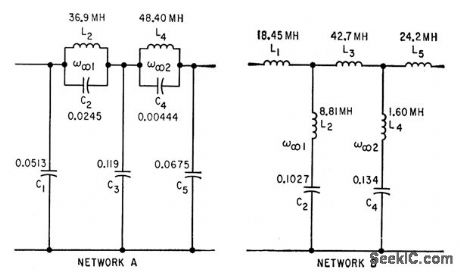
Amide gives design procedure using Caver parameters. Both examples give 40 db attenuation at 5,000 cps when inserted between 600-ohm source and load resistances.-K. Lichtenfeld, Method for Simplifying Filter Design, Electronics, 33:21, p 96-99. (View)
View full Circuit Diagram | Comments | Reading(967)
PARALLEL_T_FILTER_WITH_FEEDBACK
Published:2009/7/14 4:00:00 Author:May
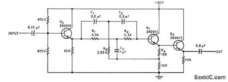
Single-transistor feedback circuit Q2 reduces high attenuation in passband that severely limits conventional 60-cps T-notch filter, Filter response is down 1 db at 62 cps. Can be used in reproducing stereo tape, where it will salvage signals normally buried far below noise level of original tape recording. -J. Strattan , Feedback Improves Filter, Electronics, 39:18, p 99. (View)
View full Circuit Diagram | Comments | Reading(1424)
3_A_LIMITER
Published:2009/7/14 3:59:00 Author:May
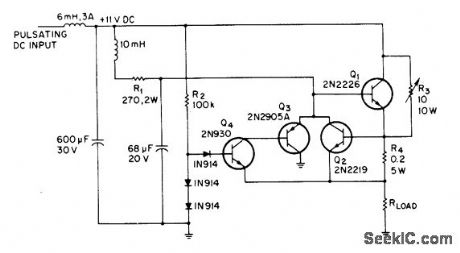
Simple current limiter protects itself from over dissipation during shorted output, while handling capacitor or cold-filament loads that momentarily act like shorts. R3 is adjusted so starting current is high enough to begin heating cold filament. As filament voltage increases to about 100 mV, Q4 and Q3 turn off, allowing load current to rise to 3-A limiting value.- L. G. Wright, Short-Protected Current Limiter Ignores Inrush Currents, EEE Magazine, Sept, 1970, p 89-90. (View)
View full Circuit Diagram | Comments | Reading(883)
ZOBEL_BAND_ELIMINATION_FILTER
Published:2009/7/14 3:59:00 Author:May
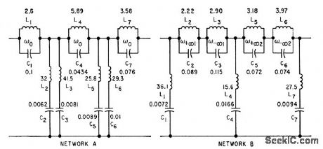
Both examples give at least 40 db attenuation between 8,410 cps and 11,150 cps, for 600-ohm source and load resistances.-K.Lichtenfeld, Method for Simplifying Filter Design, Electronics, 33:21, p 96-99. (View)
View full Circuit Diagram | Comments | Reading(753)
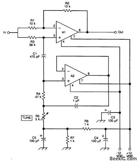
ADJUSTABLE_400_CPS_TUNING_FORK_FILTER
Published:2009/7/14 3:59:00 Author:May
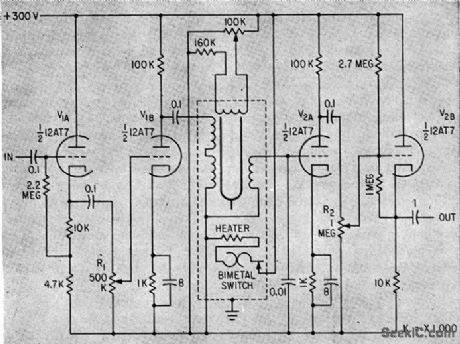
Tuning-fork frequency is adjusted by varying current in extra magnet coils facing ends of tines. Current change of 1 ma in frequency-adjust coils gives frequency change of 50 parts per million. Input and output cathode followers isolate filter from rest of circuit. Drive and pickup amplifiers cancel fork insertion loss.-J. J. O'Connor, Tuning-Fork Audio Filter Tunes Electrically, Electronics, 33:49. (View)
View full Circuit Diagram | Comments | Reading(762)
CRYSIAL_RADIOTELEGRAPH_I_F_FILTER
Published:2009/7/14 3:58:00 Author:May
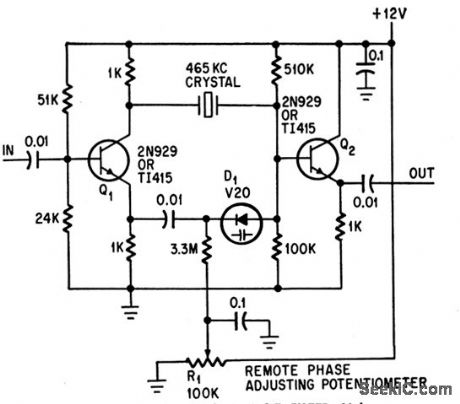
Voltage-controlled varactor diode D1 permits remote location of potentiometer used for phasing adjustment. Circuit can be used for any i-f value from 100 kc to 1.6 Mc by selecting crystal with desired frequency.-H. Olson, Remotely Tuned Crystal Filter Eliminates Tuned Transformer, Electronics, 38:23, p 113. (View)
View full Circuit Diagram | Comments | Reading(1139)
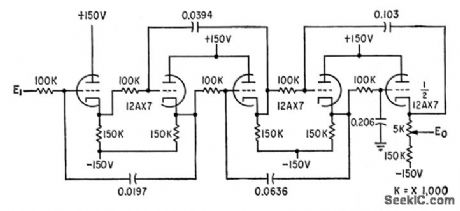
ACTIVE_ADJUSTABLE_BANDPASS_AUDIO_FILTER
Published:2009/7/14 3:49:00 Author:May

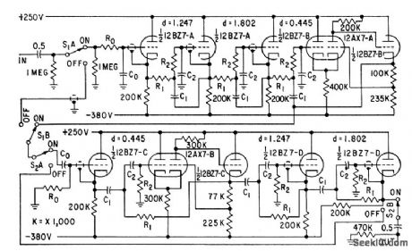
Has Butterworth attenuation characteristics and 42 db/octave cutoff slopes. Output is 50 v rms with low distortion, and dynamic range over 100 db. Second-order harmonic distortion is reduced by operating tube heaters at low voltage. Seven elements are varied simultaneously by switching different resistor and capacitor values to change cutoff frequencies. Article has three tables giving these values for high-pass cutoffs from 16 to 16,200 cps and low- pass cutoffs from 20 to 20,000 cps.-J. R. MacDonald, Active Bandpass Filter has Sharp Cutoff, Electronics, 31:33, p 84-87. (View)
View full Circuit Diagram | Comments | Reading(1871)
FET_AMPLIFIER_FOR_ACTIVE_FILTER
Published:2009/7/14 3:57:00 Author:May
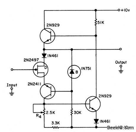
Meets gain stability and high input impedance requirements for use with third-order lowpass active filters. Uses bootstrapped source-follower. Drain of input fet drives pnp transistor in cascode to reduce input capacitance.-L. J. Sevin, Jr., Field-Effect Transistors, McGraw-Hill, N.Y., 1965, p 105. (View)
View full Circuit Diagram | Comments | Reading(1004)
ZOBEL_BAND_PASS_FILTER
Published:2009/7/14 3:57:00 Author:May

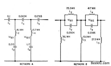
Both examples give at least 40 db attenuation below 7,500 cps and above 12,500 cps, for 600-ohm source and load resistances.-K.Lichtenfeld, Method for Simplifying Filler Design, Electronics, 33:2, p 96-99. (View)
View full Circuit Diagram | Comments | Reading(909)
ACTIVE_BUTTERWORTH_R_C_FILTER
Published:2009/7/14 3:56:00 Author:May
Article gives design procedure for selecting R and C values for active filters characterized by zero output either at zero frequency or at in infinite frequency. Symmetry of network transfer function allows choice of values by coefficient matching technique. Fifth-order low-pass filter, down 50 db at 70 cps, is shown.-R. E. Bach, Jr., Selecting R-C Values for Active Filters, Electronics, 33:20, p 82-85. (View)
View full Circuit Diagram | Comments | Reading(847)
10_W_AT_450_MHz
Published:2009/7/14 1:56:00 Author:May
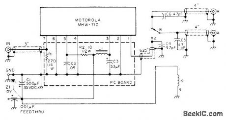
Uses Motorola MHW-710 sealed power module drawing 2.7 A on 13.8 VDC. Developed for use with fast-scan amateur TV transmitter having audio on video carrier and TR switching. Relay K1 is Archer (Radio Shack) 275-206. L1 is Ferroxcube VK200-201 4B.-B. J. Brown, Super Simple 450 MHz Rig, 73Magazine, Aug. 1976, p 72-75. (View)
View full Circuit Diagram | Comments | Reading(1284)
XENON_FLASHTUBE_CIRCUIT
Published:2009/7/13 11:14:00 Author:May
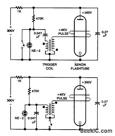
These are basic circuits for firing Xenon flashtubes. Which circuit is applicable depends on trigger coil polarity. (View)
View full Circuit Diagram | Comments | Reading(1063)
MULTIPLE_FEEDBAGK_BANDPASS_ACTIVE_FILTER
Published:2009/7/13 11:05:00 Author:May
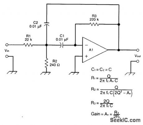
This is a multiple-feedback-path(MFP)bandpass filter. (View)
View full Circuit Diagram | Comments | Reading(1111)
ACTIVE_HP_FILTER_
Published:2009/7/13 11:04:00 Author:May
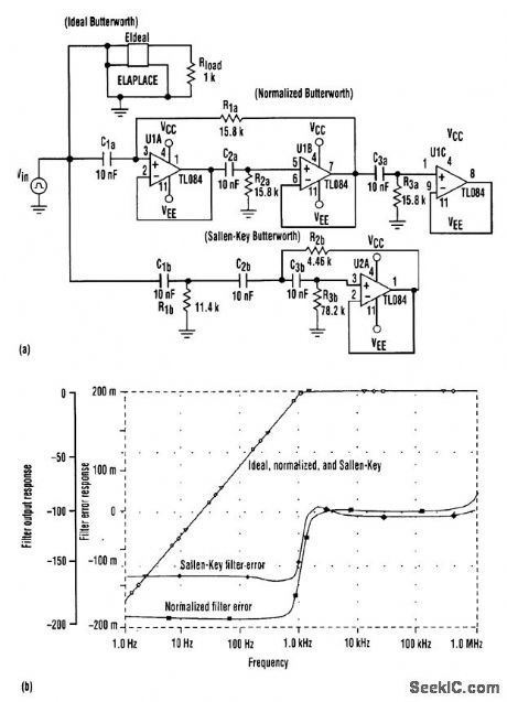
Interchanging the resistors and capacitors transforms the normalized low-pass filter into a high-pass filter with the same corner frequency (a). Notice that the Sallen-Key filter must be modified according to impedance levels at each node. This yields a filter with equal-value capacitors and unequal-value resistors, an improvement over the traditional low-pass design of equal-value resistors and unequal-value capacitors. The graphs in (b) indicate that the normalized high-pass filter compares favorably with the Sallen-Key filter in high-pass applications. (View)
View full Circuit Diagram | Comments | Reading(866)
CERAMIC_FILTER_INTERFACING
Published:2009/7/13 11:01:00 Author:May
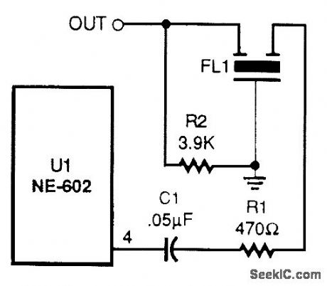
Ceramic or mechanical filters can provide a frequency-selective output. (View)
View full Circuit Diagram | Comments | Reading(690)
LOW_PASS_FILTER_PHASE_CORRECTOR
Published:2009/7/13 11:00:00 Author:May
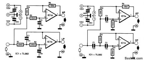
In some applications, it might be desired, or even be essential, that the bandwidth of the audio signal be limited, but that the phase relationship with the original signal be retained. A surroundsound encoder is a good example of this. The requirement can be met by combining the low-pass filter with an all-pass section and having the filtered signal compared with the signal corrected by the all-pass network. As it happens, the phase transfer of a first-order all-pass filter is exactly the same as that of a second-order critically damped network. The design of such a combination is shown in Figure 1. In this, the all-pass network is based on IC1a and the low-pass section on IC1b. The -6-dB cutoff point is at exactly 1 kHz, and the -3-dB rolloff is at 642 Hz. (View)
View full Circuit Diagram | Comments | Reading(1157)
600_TO_3000_Hz_TUNABLE_NOTCH_FILTER_CIRCUIT
Published:2009/7/13 10:54:00 Author:May
This figure shows a notch filter that will tune roughly from 600 Hz to 3 kHz; it has been used by ham and SWL builders for a number of years. It is used for notching out unwanted CW stations or for notching out heterodynes in receivqr outputs. Insert this filter between the headphone output of the receiver and a power amplifier stage. (View)
View full Circuit Diagram | Comments | Reading(880)
SUBSONIC_FILTER
Published:2009/7/13 10:52:00 Author:May
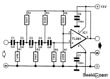
This filter is a fifth-order high-pass section that provides 1 dB attenuation at 20 Hz. Below that, however, the response drops off very steeply; the -3-dB point is at 17.3 Hz, and at 13.6 Hz, the attenuation is 10 dB. Note that it is important that C1 to C5 are within 1 percent of one another. Their individual tolerance is not so important because that merely affects the cutoff point. However, mutual deviation adversely affects the shape of the response, which should be a Butterworth characteristic as specified. All resistors are 1-percent types. (View)
View full Circuit Diagram | Comments | Reading(5071)
IF_BANDPASS_FILTER_SWITCH
Published:2009/7/13 10:31:00 Author:May
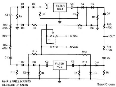
Selecting IF bandpass filters via series/shunt PIN-diode switching can be accomplished with this circuit. Diodes can be MV3404 or similar types. (View)
View full Circuit Diagram | Comments | Reading(853)
CAPACITORLESS_NOTCH_FILTER
Published:2009/7/13 10:29:00 Author:May
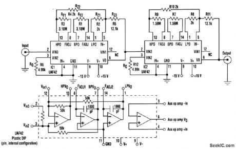
The notch frequency for the filter is set by fnotch+[(ALP/AHP)×(RZ2/RZ1)]×f0where ALP and AHP are the gain from input to low-pass output at f=0 Hz,and the gain from input to high-pass output at f≤f0,respectively. Typically ((ALP/AHP)×(RZ2/RZ1)=1;therefore,fnotch=f0,and is gtven by f0=1/(2π)(RFC)where RF=RF1=RF2, and C=C1=C2. The -3-dB bandwidth is determined by the following relation∶BW-3dB=fnotch/Q, where BW-3dB=fH-fL. The Q of the filter affects the passband gainc(which should be adjusted to unity) and is related to the ratio of the resistances RZ3 to RZ1 and RZ3 to RZ2. In other words,Q=(RZ3/RZ1)=(RZ3/RZ2). Q also is related to RQ by the follOwing relation∶RQ=(25 kΩ/Q-1). (View)
View full Circuit Diagram | Comments | Reading(1115)
| Pages:4/21 1234567891011121314151617181920Under 20 |
Circuit Categories
power supply circuit
Amplifier Circuit
Basic Circuit
LED and Light Circuit
Sensor Circuit
Signal Processing
Electrical Equipment Circuit
Control Circuit
Remote Control Circuit
A/D-D/A Converter Circuit
Audio Circuit
Measuring and Test Circuit
Communication Circuit
Computer-Related Circuit
555 Circuit
Automotive Circuit
Repairing Circuit