
Filter Circuit
Index 17
SIMPLE_HIGH_PASSHP_ACTIVE_FILTER_FOR_1_kHz
Published:2009/6/16 21:08:00 Author:May
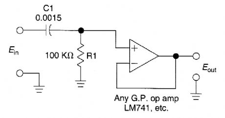
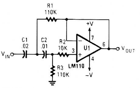
This simple 1kHz filter uses a voltage follower and an RCsection for a filter element,For other frequencies f3 dB-1/6.28 R1C1. The response drops 6 dB/octave below f3 dB. (View)
View full Circuit Diagram | Comments | Reading(811)
ACTIVE_FOURTH_ORDER_HIGH_PASS_FILTER_FOR_50_Hz
Published:2009/6/16 21:08:00 Author:May
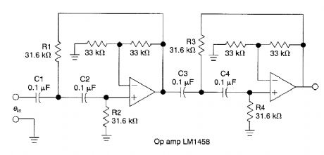
This circuit which uses an LM1458 or similar op amp is a fourth-order high-pass filter with a 24 dB/octave roll-off The values of R1/R2,R3/R4,C1/C2,C3/C4 can be scaled to suit other cutofffre quencies (View)
View full Circuit Diagram | Comments | Reading(1707)
ACTIVE_UNITY_GAIN_SECOND_ORDER_LOW_PASS_FILTER
Published:2009/6/16 3:05:00 Author:May
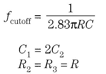
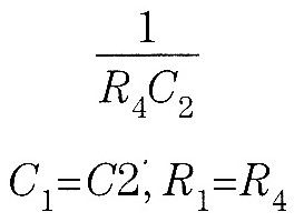
This second-order Butterworth filter cuts off near 10 kHz. The values of C1and C2 can be changed to alter the frequency, or else calculated from the formula.
(View)
View full Circuit Diagram | Comments | Reading(1282)
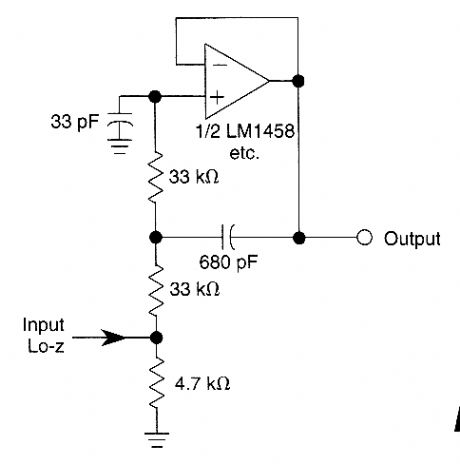
UNITY_GAIN_SECOND_ORDER_HIGH_PASS_FILTER
Published:2009/6/16 3:03:00 Author:May

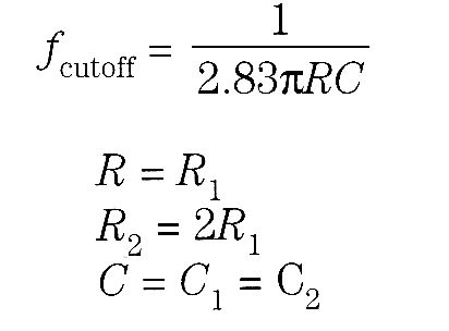

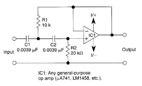
This filter circuit has a cutoff frequency of 2900 Hz with the values shown
(View)
View full Circuit Diagram | Comments | Reading(860)
1_mV_OFFSET,CLOCK_TUNABLE,MONOLITHIC_5_POLE_LOW_PASS_FILTER
Published:2009/6/16 3:02:00 Author:May
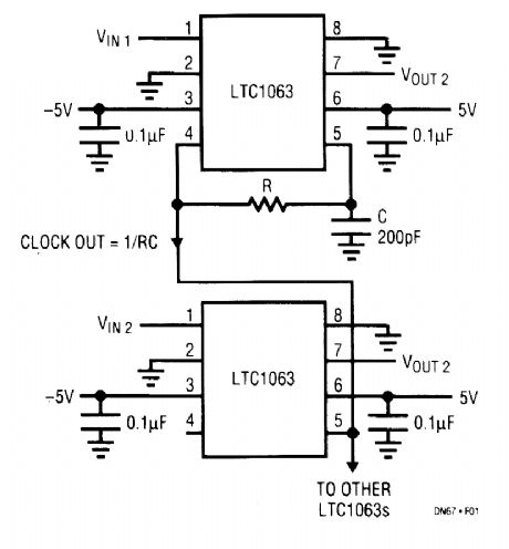
The LTC1063 is the first monolithic low-pass fil-ter that simultaneously offers outstanding dc and ac performance. It features internal or external clock tunability, cutoff frequencies up to 50 kHz, 1-mV typ-ical output dc offset, and a dynamic range in excess of 12 bits for over a decade of input voltage.The LTC1063 approximates a 5-pole Butterworth low-pass filter. The unique internal architecture of the filter allows outstanding amplitude matching from device to device. Typical matching ranges from 0.01 dB at 25% of the filter passband to 0.05 dB at 50% of the filter passband.An internal or external clock programs the filter's cutoff frequency. The clock-to-cutoff frequency ratio is 100:1. In the absence of an external clock, the LTC1063's internal precision oscillator can be used. An external resistor and capacitor set the device's internal clock frequency. (View)
View full Circuit Diagram | Comments | Reading(768)
VARIABLE_HIGH_PASS_FILTER
Published:2009/6/16 2:54:00 Author:May
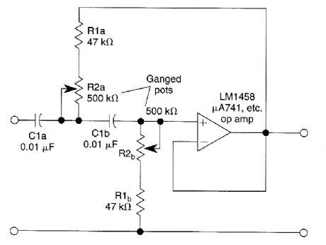
This second order filter which should prove useful in audio applications uses an LM1458 or other similar of op amp. It is tuneable from 30 to 300 Hz cutoff. R2a, b are ganged log-taper poten-tiometers. (View)
View full Circuit Diagram | Comments | Reading(988)
VARIABLE_LOUW_PASS_FILTER
Published:2009/6/16 2:53:00 Author:May
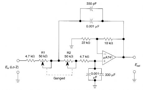
This second-order low-pass filter uses a 741 op amp and is tuneable from 2.5 kHz to 25 kHz.This circuit is useful in audio and tone control ap-plications. R1 and 2 are ganged potentiometers. (View)
View full Circuit Diagram | Comments | Reading(1676)
VARIABLE_FREQUENCY_AUDIO_BP_FILTER
Published:2009/6/16 2:53:00 Author:May
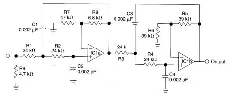
This variable-frequency, audio bandpass filter is built around two 741 op amps that are connected in cascade. Tro 741 op amps are configured as identical RC active filters and are connected in cascade for better selectivity. The filter's tuning range is from 500 Hz to 1500 Hz. The overall volt-age gain is slightly greater than 1 and the filter's is about 5. The circuit can handle input signals of 4 V peak-to-peak without being overdriven. The circuit's input impedance is over 200 kQ and its output impedance is less than 1 kQ. (View)
View full Circuit Diagram | Comments | Reading(2904)
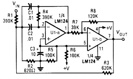
ACTIVE_SECOND_ORDER_BANDPASS_FILTER_FOR_SPEECH_RANGE
Published:2009/6/16 2:45:00 Author:May
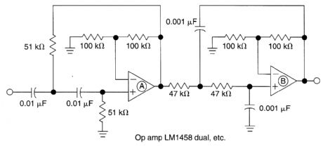
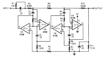
This filter circuit which uses LM1458 or similar op amp has a response of 300 Hz to 3.4 kHz with 12 dB/octave roll-off outside the pass band. Section A is the high-pass one, followed by Iow-pass sec-tion B. Values of either section can be scaled to alter the pass band. (View)
View full Circuit Diagram | Comments | Reading(1938)
ACTIVE_FOURTH_ORDER_LOW_PASS_FILTER
Published:2009/6/16 2:42:00 Author:May
This circuit is a fourth-order low-pass filter with values for kHz. The values of R1,R2,C1 and C2, and R3, R4, C3 and C4 can be scaled for operation at other frequencies. Roll-off is 24 dB/octave. (View)
View full Circuit Diagram | Comments | Reading(1189)
VARIABLE_BANDPASS_AUDIO_FILTER
Published:2009/6/16 2:41:00 Author:May
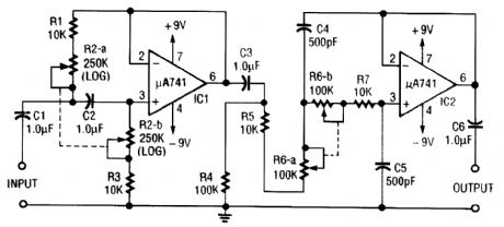
This circuit is a variable audio bandpass filter that has a low cutoff variable from about 25 Hz to 700 Hz and a high cutoff variable from 2.5 kHz to over 20 kHz. Rolloff is 12 dB/octave on both high and low ends. R2-a-b and RG-a-b are ganged potentiometers for setting lower and upper cutoff fre-quencies, respectively. (View)
View full Circuit Diagram | Comments | Reading(4255)
TWIN_T_NOTCH_FILTER_FOR_1_kHz
Published:2009/6/16 2:39:00 Author:May
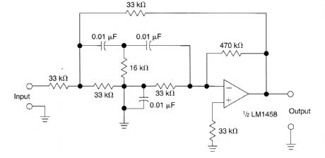
The circuit shown uses a twin T notch filter and an amplifier. Used to remove unwanted frequency. (View)
View full Circuit Diagram | Comments | Reading(1359)
VARIABLE_Q_FILTER_FOR_400_Hz
Published:2009/6/16 2:39:00 Author:May
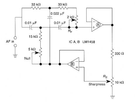
A bootstrapped twin T notch filter in this circuit can yield an effective Q of up to 10. RS adjusts the feedback, hence the Q. Values of C1 and C2 can be changed to alter the frequency. RF is a fine-tune null control. (View)
View full Circuit Diagram | Comments | Reading(1100)
FOUR_OUTPUT_FILTER
Published:2009/6/16 2:37:00 Author:May
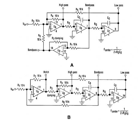
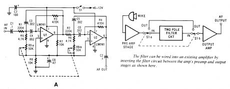
The classic state-variable (two-integrator) filter (see Fig. A) is famous for its insensitivity to device parameter tolerances, as well as its ability to provide three simultaneous separate outputs: high pass, bandpass, aind low pass. These advantages often offset the fact that a quad operational amplifier is needed to implernent the circuit.A modification of the classic scheme that applies the input voltage via amplifier U,, rather than UD provides a bandpass output with a fixed peak gain that doesn't depend on the Q of the filter. It was found by using that conftguration, a fourth notch-filter output can be obtained if R1=R6 (see Fig. B).If R1=R6=R12 the gains of both the notch and bandpass outputs are unity, regardless of the Q factor, as determined by R3, R1, R2, R4, R5, and R6. The resonant (or cutoff) frequency is given by ω -1/RO×CO Depending on the capacitor values and frequency ω, resistance RO might also share the same monolithic network for maximum space economy. As with the classic configuration, reso-nant frequency ω can be electrically controlled by switching resistors RO, or by using analog multi-pliers in series with the integrators. (View)
View full Circuit Diagram | Comments | Reading(758)
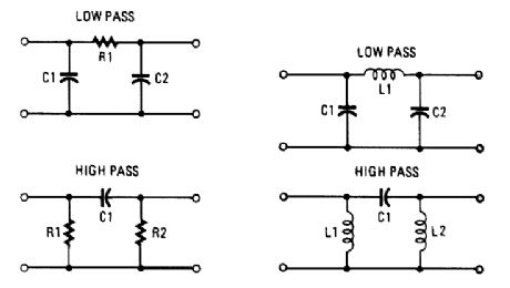
PASSIVE_PI_FILTER_CONFIGURATIONS
Published:2009/6/16 2:33:00 Author:May
View full Circuit Diagram | Comments | Reading(868)
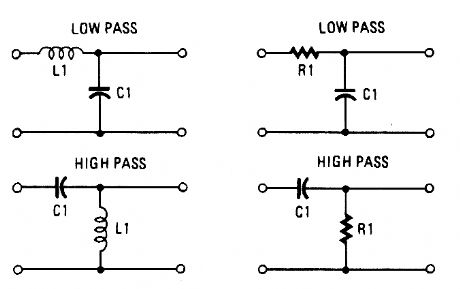
PASSIVE_L_FILTER_CONFIGURATIONS
Published:2009/6/16 2:32:00 Author:May
View full Circuit Diagram | Comments | Reading(808)
ACTIVE_LOW_PASS_RC_FILTER
Published:2009/6/16 2:32:00 Author:May
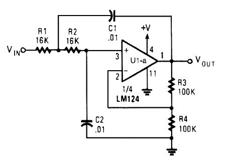
The circuit shown has a cutoff frequency at about 1 kHz. R1, R2, C1, and C2 can be scaled to change this to any other desired frequency. (View)
View full Circuit Diagram | Comments | Reading(1009)
BANDPASS_FILTER_1
Published:2009/6/16 2:32:00 Author:May
Appropriate center frequency of this circuit is:
(View)
View full Circuit Diagram | Comments | Reading(698)
400_Hz_LOW_PASS_BUTTERWORTH_FILTER
Published:2009/6/16 2:30:00 Author:May
Designed for a 400-Hz cutoff frequency, the cutoff can be scaled by varying the element values proportionally to frequency (View)
View full Circuit Diagram | Comments | Reading(794)
ACTIVE_HIGH_PASS_FILTER
Published:2009/6/16 2:27:00 Author:May
View full Circuit Diagram | Comments | Reading(957)
| Pages:17/21 1234567891011121314151617181920Under 20 |
Circuit Categories
power supply circuit
Amplifier Circuit
Basic Circuit
LED and Light Circuit
Sensor Circuit
Signal Processing
Electrical Equipment Circuit
Control Circuit
Remote Control Circuit
A/D-D/A Converter Circuit
Audio Circuit
Measuring and Test Circuit
Communication Circuit
Computer-Related Circuit
555 Circuit
Automotive Circuit
Repairing Circuit