
Filter Circuit
Index 9
VOICE_BANDPASS
Published:2009/7/3 4:14:00 Author:May
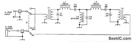
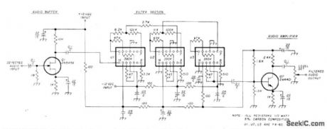
Used between 8-ohm output of communication receiver and 8-ohm Loud-speaker or low-impedance phones, to suppress Continuous Random Unwanted Disturbances on voice transmissions. Passband is 355 to 2530 Hz at 3-dB points. L1 and L3 are 4a-mH toroids.L2 is 88-mH toroid with 94 turns removed. T1 and T2 are 88-mH toroids with 100 turns No.28 enamel wound over original winding of each for primary.-R. M. Myers, The SSB Crud-O-Ject, QST, May 1974, p 23-25 and 56 (View)
View full Circuit Diagram | Comments | Reading(1456)
2955_MHz_HIGH_PASS
Published:2009/7/3 4:13:00 Author:May
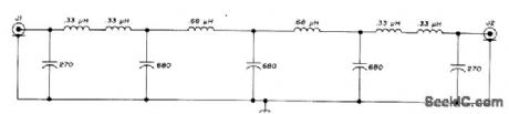
Used in offset frequency-measuring system for amateur-band signals. Nine-section Chebvshev high-pass filter with 1-dB passband ripple attenuates undesired 2.045-2.245 MHz image 16 dB while selecting desired 2.955-3.155 MHz signal. Filterhas sharper cutoff characteristic, for given num ber of sections, than Butterworth or image parameter designs.-J. Walker, Accurate Frequency Measurement of Received Signals, Ham Radio, Oct. 1973, p 38-55. (View)
View full Circuit Diagram | Comments | Reading(759)
LOW_PASS_WITH_425_MHz_CUTOFF
Published:2009/7/3 4:12:00 Author:May
Designed for insertion in antenna coax of amateur radio station up to 1 kW, to cure TVI Problems.Provides 60-dB attenuation on channel 2. Filter uses mderived terminating half-sections at each end, with two constant-K midsections.End sections are tuned either to channel 2 (55 MHz) or channel3(61 MHz), Article covers construction and tune-up.-N. Johnson, High-Frequency Lowpass Filter, Ham Radio, March 1975, p 24-27. (View)
View full Circuit Diagram | Comments | Reading(762)
PROGRAMMER_FOR_SIGNETICS_8223
Published:2009/7/3 4:10:00 Author:May


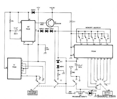
Bounceless switch U1 triggers mono MVBR U2, both operating at 7 V above ground. When Q1is saturated by pulse from U2, it applies 250-ms 12.5-V programming pulse to VCC terminal (pin 16) of memory chip and opens fuse at previously addressed bit to make it logic 1. Separate regulators are required for 7 V and 12.5 V. Used with alphameric display having five 7-segment digits in circuit serving as function/units indicator for interval timericounter, where it forms simulation of abbreviations for time and frequency units. Articlegives step-by-step instructions for mistake-free operation of programmer.-J. W. Springer, Function/Units Indicator Using LED Displays, Ham Radio, March 1977, p 58-63. (View)
View full Circuit Diagram | Comments | Reading(1004)
FOUR_CRYSTAL_FILTER
Published:2009/7/3 4:10:00 Author:May
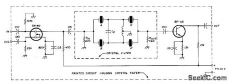
Uses two matched sets of crystals, with each pair having maximum frequency difference of 25 Hz.Transistors serve as input and output isolating stages. Each matched pair, such as A-A', should be from same manufacturer and have same nominal parallel capacitance for circuit, same activity, and same resonant frequency within 25 Hz. Artide gives detailed instructions for grinding crystal to increase resonant frequency when necessary for matching. Use frequency counter for checking frequency. Values given in circuit are for 5.645-MHz crystal filter with -6dB band-pass of L82 kHz and insertion loss of about 5 dB. Crystals used are 5.644410 MHz and 5.644416 MHz for A and A', and 5.645627 MHz and 5.645641 MHz for B and B'. Coil has 7 + 7 turns No.28 enamel bifilar wound on 10.7-MHz IF transformer having 2.4-mm slug diameter. C, is 39 to 47 pF.-J. Perolo, Practical Considera-tions in Crystal-Filter Design, Ham Radio. Nov.1976, p 34-38.
(View)
View full Circuit Diagram | Comments | Reading(1307)
2125_Hz_LOW_PASS
Published:2009/7/3 4:09:00 Author:May
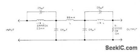
Used with AFSK keyer to convert 2125-Hz square wave to sine wave by removing third and fifth harmonics. All three coils are toroids, with its two windings in series for 88 mH and in parallel for 23 mH.-L.J.Fox,Dodge That Hurricane!,73 Magazine,Jan. 1978, p 62-69. (View)
View full Circuit Diagram | Comments | Reading(720)
DIODE_SWITCHED_FOUR_CRYSTAL_IF_FILTER
Published:2009/7/3 4:08:00 Author:May
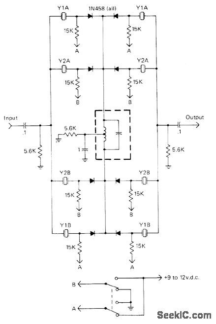
Appiication of 9-12 VDC to control points A or B gives choice of two different selectivities for IF amplifier in amateur communication receiver.For 500-Hz bandwidth at 455 kHz, frequencies of crystals in use should be 300 Hz apart for CW, 1.8 kHz apart for 2.7-kHz SSB bandwidth, and 1.25 kHz apart for 2.1-kHz SSB bandwidth. Article gives design graphs.-J. J. Schultz, Economical Diode-Switched Crystal Filters, CQ, July 1978, p 33-35 and 91. (View)
View full Circuit Diagram | Comments | Reading(853)
160_METER_BANDPASS
Published:2009/7/3 3:43:00 Author:May
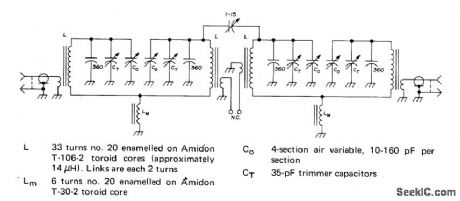
Four-resonator filter is tunable from 1.8 to 2 MHz and has insertion loss of 5 dB.3-dB bandwidth is 30 kHz,and 6-60 dB shape factor is 4.78.Stopband attenuation is over 120 dB.Key to high performance is ward,Bandpass Filters for Receiver Preselecconstruction,and adjustment.-W. Hayward,Bandpass Filter for Receiver Preselectors,Ham Radio,Feb,1975,p 18-27. (View)
View full Circuit Diagram | Comments | Reading(961)
BANDPASS_FOR_CW
Published:2009/7/3 3:42:00 Author:May

Provides bandwidth of about 400 Hz (3 dB down) centered on 875 Hz, for improving reception of CW signals with amateur receiver. Uses three 44-mH toroids.-D. C.Rife, Low-Loss Passive Bandpass CW Filters, QST, Sept. 1971, p 42-44. (View)
View full Circuit Diagram | Comments | Reading(0)
CW_FILTER_FOR_INTERFERENCE
Published:2009/7/3 3:41:00 Author:May
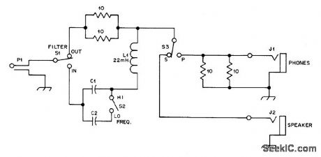
Audio bandpass filter, designed for connection between loudspeaker jack of receiver and external loudspeaker or phone, has half-power bandwidth of about 70 Hz but rolls off gradually without causing ringing, Series LC combination, connected in hot line to loudspeaker,looks like 5-ohm re sistance at resonance, cutting signal amplitude about in half. At Iower frequencies filter looks like large capacitive reactance and at higher frequencies it resembles large inductive reactance, both causing high attenuation. Filter thus discriminates against all except switch-selected resonant frequency, either 760 or 1070 Hz.Choose best frequency for particular receiving situation by trial.-F. Noble, A Passive CW Filter to improve Selectivity, QST, Nov. 1977, p 34-35. (View)
View full Circuit Diagram | Comments | Reading(1289)
505_MHz_BANDPASS
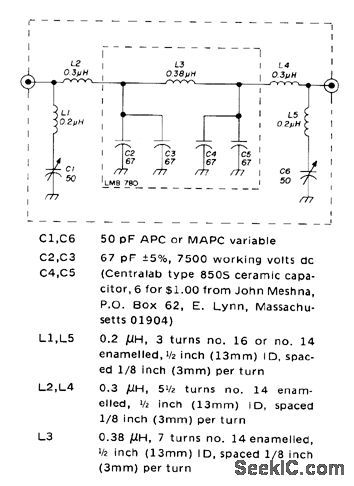
Published:2009/7/3 3:39:00 Author:May
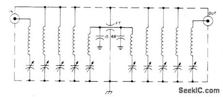
Provides 60% band-width with only 4-dB insertion loss Each coil is about 2.2μH,and trimmer capacitors are 1.5-7 pF Sweep signal generator and 5-in CRO are essential for alignment.-P. H.Sellers, 50-MHz Bandpass Filter, Ham Radio, Aug. 1976, p 70-71. (View)
View full Circuit Diagram | Comments | Reading(799)
ELLIPTIC_HIGH_PASS_LOW_PASS
Published:2009/7/3 3:38:00 Author:May
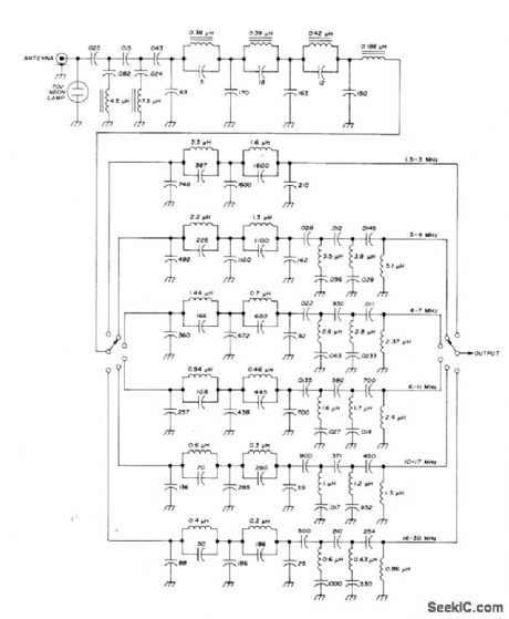
Covers 1.45 to 32 MHz in six steps, for use at front end of high-frequency communication receiver to suppress unwanted broadcast signals. Low-pass filter section, acting with one of six following low-pass sections, gives over 90-dB image suppression. Special Bessel-Cauer elliptic filter having Chebyshev response in passband provides required 50-ohm impedance matching so filters can be cascaded.-U. L. Rohde, Optimum Design for High-Frequency Communications Recoivers, Ham Fladio, Oct. 1976, p 10-25.
(View)
View full Circuit Diagram | Comments | Reading(1254)
1_kHz_BANDPASS_HIGH_Q
Published:2009/7/3 3:02:00 Author:May

Shunt-switched bandpass filter with o of 1000 and voltage gain of about 7 uses DG508 CMOS multiplexer containing required analog switches,interface cicuhs, and deoode logic for 8-path filter. Bandwidth for 3 dB down is 1 Hz centered on 1 kHz, with asymptotic slope of 6 dB per octave. Clock controls shunt-switched filter action.- Analog switches and Their Applications, Siliconix,Santa Clara,CA,1976,p 5-12-5-14. (View)
View full Circuit Diagram | Comments | Reading(1083)
700_2000_Hz_TUNABLE_BANDPASS
Published:2009/7/3 2:58:00 Author:May
Uses RC notch circuit as feedback element for active-filter opamp. With tuning pot set for center frequency of 1000 Hz, 3-dB bandwidth is 23 Hz and 10-dB bandwidth is 68 Hz. At 1000 Hz, voltage gain is 36 dB. High-frequency rolloff is good, being 43 dB down at 2000 Hz, so circuh converts 1000-Hz square wave into sine wave. Artide gives design equations.-C. Hall, Tunable RC Notch Filter, Ham Radio, Sept. 1975, p 16-20. (View)
View full Circuit Diagram | Comments | Reading(1289)
BANDPASS_FOR_CW
Published:2009/7/3 2:57:00 Author:May
Sophisticated audio processing system for CW bandpass, using communication receiver, has actual bandpass center frequency between 900 and 950 Hz.Bandwidth is about 150 Hz Minimum relative attenuation is above 20 dB,Uses three KineticTechnology FX-60 ICs(cuned from FS-60,FS-65,and FS-61 production by manufacturer).-M. A.Chapman, Audio Filters for Improving SSB and CW Reception, Ham Radio, Nov.1976, p 18-23. (View)
View full Circuit Diagram | Comments | Reading(1444)
1_kHz_BANDPASS_NOTCH
Published:2009/7/3 2:54:00 Author:May
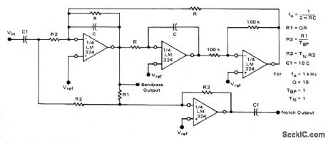


Biquad filter uses all four sections of LM324 quad differential-input opamp to provide choice of bandpass and notch outputs. Supply voltage range can be 3-32 v, with reference voltage equal to half of supply value used. For center frequency of 1 kHz,R is 160K, C is 0.001 μF, and R1-R3 are 1.6 megohms,Coupling capactions C1 can be 10 times value used for C.- Low Power Operational mplifiers, Motorola,Phoenix,AZ,1978,DS9339 R1. (View)
View full Circuit Diagram | Comments | Reading(1689)
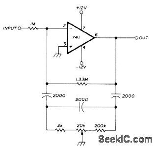
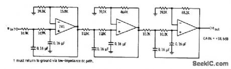
SECOND_ORDER_1_kHz_LOW_PASS
Published:2009/7/3 2:52:00 Author:May
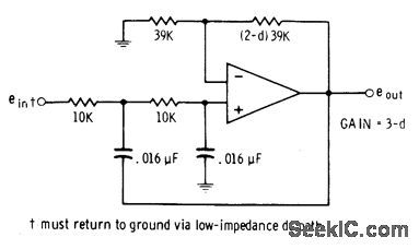
Circuit using 741 opamp has equalvalue series input resistors and high-pass capacitors. Cutoff frequency can be increased by changing 10K resistors to higher values while keeping their values identical. 10:1 resistance change provides 10:1 frequency change. Damping d is adjustable; critical value of 1.414 gives maximum flatness of response without overshoot. Interchange 10K resistors and 0.016-μF capacitors to convert circuit to 1-kHz high-pass filter.-D. Lancaster, Active-Filter Cookbook, Howard W. Sams, indianapolis, IN, 1975, p 127-129. (View)
View full Circuit Diagram | Comments | Reading(997)
600_Hz_THIRD_ORDER__LOW_PASS
Published:2009/7/3 2:51:00 Author:May
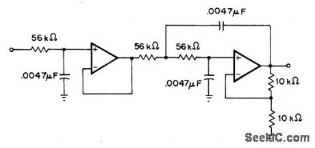
Butter-worth filtor using 741 or equivalent opamp provides gain of 6 dB in passband below 600-Hz cutoff,All components can be 5% tolerance.- H.M.Berlin, Design of Active Filters,with Experiments, Howard W Sams, Indianapolis, IN,1977,p 114-116. (View)
View full Circuit Diagram | Comments | Reading(812)
10_Hz_LOW_PASS
Published:2009/7/3 2:31:00 Author:May
Filter design for biomedical experiment has 10-Hz cutoff, tolerable transient and overshoot response, and at least 30-dB rejection of all frequencies above 15 Hz. All components should have 2% tolerance.-D. Lancaster, Active-Filter Cookbook, Howard W.Sams, lndianapolis, IN, 1975, p 147. (View)
View full Circuit Diagram | Comments | Reading(1174)
18_19_MHz_BANDPASS
Published:2009/7/3 2:25:00 Author:May
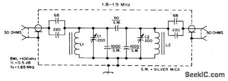
Butterwolth bandpass filter, suitable for use with broadband preamp, helps reject out-of-band signals. Filter also protects preamp from signals across response range from broadcast band through VHF. C1 and C2 are mica trimmers. L1 and L2 have 30 turns No. 22 enamel on Amidon T68-6 toroid cores to give 5.1 μH.-D. DeMaw, Beat the Noise with a Scoop Loop, QST, July 1977, p 30-34. (View)
View full Circuit Diagram | Comments | Reading(825)
| Pages:9/21 1234567891011121314151617181920Under 20 |
Circuit Categories
power supply circuit
Amplifier Circuit
Basic Circuit
LED and Light Circuit
Sensor Circuit
Signal Processing
Electrical Equipment Circuit
Control Circuit
Remote Control Circuit
A/D-D/A Converter Circuit
Audio Circuit
Measuring and Test Circuit
Communication Circuit
Computer-Related Circuit
555 Circuit
Automotive Circuit
Repairing Circuit