
Basic Circuit
Index 374
Full Bridge DC/DC Converter Circuit
Published:2011/6/24 1:52:00 Author:Michel | Keyword: Full Bridge, DC/DC, Converter Circuit
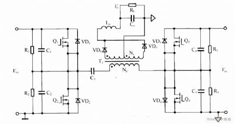
The full bridge DC/DC converter circuit is shown as above.Full bridge DC/DC converter are mainly used in high-power power supply and it has following features.First,transformer utilization rate is rather high, unloaded energy can give feedback to the power grid, the power supply has high efficiency.Second,there is no steady-state error at stable state and it responses quickly in dynamic condition and the system is stable and it has high anti-interference ability to high frequency.
Picture:Full Bridge DC/DC Converter Circuit (View)
View full Circuit Diagram | Comments | Reading(1517)
Air-conditioning Circuit Two of Southeast LingShuai Cars
Published:2011/7/7 21:18:00 Author:Michel | Keyword: LingShuai Cars, Air-conditioning Circuit Two
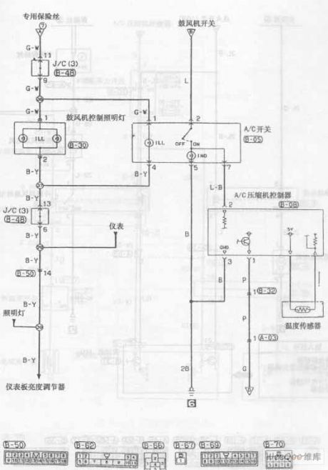
Air-conditioning Circuit of Southeast LingShuai Cars (View)
View full Circuit Diagram | Comments | Reading(777)
Fan Speed Control Circuit of MAX1626
Published:2011/6/26 7:01:00 Author:Michel | Keyword: Fan, Speed Control, Circuit

The aboved picture is fan speed control circuit composed of MAX1626.This circuit reduces the computer, the temperature controller and alarm system noise and power consumption by choosing the MDH626 shut-off and the output voltage function. Logic level is added to 2 (3 V / 5 V) and 3 (SHDN) pins and at the same time,feedback resistance (Rl and R2) are chosen to set the output voltage.Usually, a low output voltage U (01) (here it's eight V) is determined by dividing resistor R1 and R2.High output voltage U (02) here it's l2V) is determined by chip the output (4 feet) voltage.When environment temperature is more than the threshold values within the chip, the MAX6501 (1) and (2) leakage output(TOVER) of monitoring temperature becomes low PWL. (View)
View full Circuit Diagram | Comments | Reading(869)
110V/220V AC Voltage Automatic Switch-over Circuit
Published:2011/6/22 9:52:00 Author:Michel | Keyword: 110V/220V, AC Voltage, Automatic Switch-over, Circuit
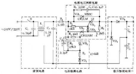
The picture is 110V/220V AC automatic switch-over circuit.When input AC voltage is 110V,charging voltage of the voltage test circuit's capacitance C3 is lower than voltage regulator tube VD6's stable voltage,V2 and thyristor VS2 shuts off ,VS1 conducts via R3 and VD2's trigger.Besides,diode VD3 is anti-paralleled with VS1 thus the latter level rectifier circuit works normally.C4 charging voltage is higher than V7 and VS2 conducts when the input voltage is 220V.As a result,None of current flows through VS1's gate level and the switch keeps off condition.The latter level times voltage turns to half wave rectifier circuit. (View)
View full Circuit Diagram | Comments | Reading(4880)
Simple Circuit of Clock Phase Adjustment
Published:2011/6/22 7:03:00 Author:Michel | Keyword: Clock Phase Adjustment, Simple Circuit
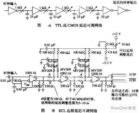
The picture shown in picture A is a hexadecimal inverter which is used to generate 30~160NS delay.Delay time of every level is 5~35NS and its value depends on variable resistance value.Delay time of every level should not be over 12% of the clock cycle to ensure stable work.
The circuit's dutyfactor can be adjusted and reaches the mininmum value by adjusting the delay levels (2 or 4) and adjusting every level resistance.It's better to adjust the shape by using an opposite phase at least at the end of the circuit before the signal entering the system.
The weakness of the circuit shown in picture A is that the circuit is the signal must pass the potentiometer. (View)
View full Circuit Diagram | Comments | Reading(761)
Thyristor AC Automatic Voltage Control and Regulation Circuit
Published:2011/6/20 21:33:00 Author:Michel | Keyword: Thyristor, AC, Voltage Control and Regulation, Circuit
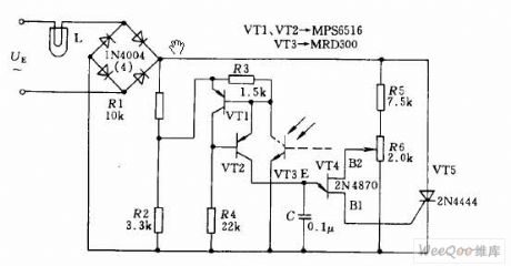
The circuit shown as above uses thyristor AC automatic voltage regulating circuit to stabilize the brightness of projector lamps,L.For this,it accesses thyristor T5 via a diagonal line of communication bridge.And its triggering pulse is generated by single thyristor VT4.Thyristor VT1,VT2 and light activated triode VT3 have the equivalent resistance function.When projection's light changes as the power supply alters,resistance value of light activated triode changes,the voltage phase of the control junction transistor alters.The aboved changes trigger thyristor' pusle phase shift and increasing or reducing thyristor conduction time makes voltage and brightness of the light projection approximately remains unchaged,which stablizes the lightness. (View)
View full Circuit Diagram | Comments | Reading(2022)
wireless remote control massor circuit
Published:2011/7/8 23:32:00 Author:Lena | Keyword: wireless, remote control, massor
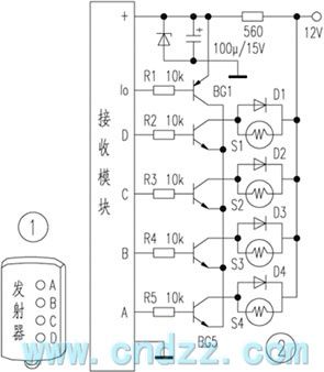
This remote control massor is used to knead waist, shoulder damage, and it has effectivity on health care and curing the injury. Because of small bulk, you can take with it anytime. Gently press a emitter key, the point can have abundant rubdown. Now introduce the manufacture method of this remote control massor, somebody interested in this can try it.
Figure 1 is a keychain multi-way wireless remote control emitter, and has A, B, C, D four keys.
(View)
View full Circuit Diagram | Comments | Reading(612)
TOSHIBA 2500XH pincushion correction circuit
Published:2011/7/8 20:09:00 Author:Lena | Keyword: pincushion correction
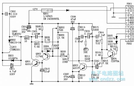
Circuits which are the same as TOSHIBA 2500XH pincushion correction circuits have the following types: TOSHIBA 2506XH, 2800XH, 2806XH etc.Field saw tooth wave voltage is sent to B pole of QD03 by (3) pin of PD02, RD17, CD 14, RD 16, RD19 and CD10. QD04 is a 50Hz/60Hz switch electronic on-off, when it is at 50Hz, QD04 is cut-off, when at 60 Hz, QD04 is conducted, then RD19 becomes a short circuit, the extent of saw tooth wave sent to QD03B pole is augment.
QD03 is a field parabolic wave voltage forming tube, at C pole, the tube outputs a sunken parabolic wave voltage, which is added to B pole of QD02 after accommodated amplitude by RD51, QD02 and QD01 are parabolic wave amplifier tube, RD50 is a row extent regulation potentiometer.
(View)
View full Circuit Diagram | Comments | Reading(935)
Typical Applied Circuit of ZXSC310
Published:2011/6/19 5:32:00 Author:Michel | Keyword: Typical Applied Circuit
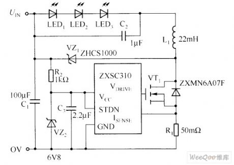
The showing circuit provides a drive power white LED solutions, that is,white LED is driven by working in the buck model of standard boost converter.This solution efficiency is as high as 96%, compared with standard solution efficiency with only 85%, it has a lot of practical advantages.
When MOSFET (VT1) turns on ,the current flows through white LED and it connects with filter capacitor(C2),inductance (L1) and test resistor(R1) in series-parallel way.The current value is decided by test resistor value and test voltage threshold of ZXSC310(It's usually 19mV). (View)
View full Circuit Diagram | Comments | Reading(1332)
Fixed Bias Voltage and Current-limiting Resistor Drive LED Circuit
Published:2011/6/19 6:51:00 Author:Michel | Keyword: Fixed Bias Voltage, Current-limiting Resistor, Drive, LED Circuit
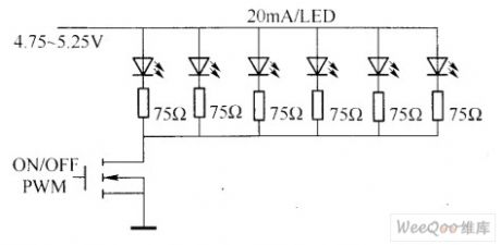
In the application of white LED the most obvious problems is the matching differences of the product.According to white LED typical specifiactions,when the current is 20mA,the minimum value of the forward voltage is 3.5V and the maximum value is 4.0V.Obviously, constant voltage source is not reasonable solution.The same current drives every LED, which can get brightness but the cost is high.Most applications are simply using fixed bias voltage and current limit resistance to obtain approximate matching white LED brightness and it is showed as above.
Picture:Fixed Bias Voltage and Current-limiting Resistor Drive LED Circuit (View)
View full Circuit Diagram | Comments | Reading(904)
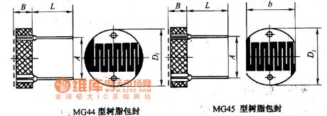
MG45 and MG44 resin package circuit
Published:2011/7/8 5:50:00 Author:Christina | Keyword: resin package
View full Circuit Diagram | Comments | Reading(575)
Unijunction semiconductor tube trigger circuit
Published:2011/7/8 5:49:00 Author:Christina | Keyword: Unijunction, semiconductor tube, trigger circuit

This device can be used in wide range of applications, the trigger pulse is mainly produced by the unijunction semiconductor tube.
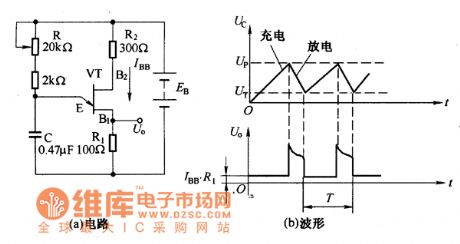
By using the characteristics of the unijunction semiconductor tube and the RC charging and discharging circuit, we can form the oscilation circuit, this circuit is as shown in the figure. The VT is the unijunction semiconductor tube.
The waveform and the oscillation circuit of the unijunction semiconductor tubeThe circuit in the figure uses the bridge rectifier and it also uses the same power supply with the main circuit to achieve the synchronization. The URL is the voltage of load.
Unijunction semiconductor tube trigger circuit
The waveform of the power supply which is rectified by the bridge rectifier circuit is as shown in the figure, it supplies the synchronous power to the trigger circuit. When the AC power supply voltage crosses zero, the UZ voltage is zero too, at this time the voltage between the two base electrodes of the VT is UBB=0, the peak point voltage Up of the VT is about zero, the VT and E-B conduct, the capacitor C will discharge all of the electric charge quickly. (View)
View full Circuit Diagram | Comments | Reading(708)
The circuit of the electric transducer
Published:2011/7/8 5:52:00 Author:TaoXi | Keyword: electric transducer
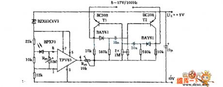
The circuit of the electric transducer is as shown in the figure:
(View)
View full Circuit Diagram | Comments | Reading(697)
Sawtooth Wave Generating Circuit Synchronous with Industrial Frequency Power
Published:2011/7/8 22:52:00 Author:Michel | Keyword: Industrial Frequency, Sawtooth Wave, Generating Circuit
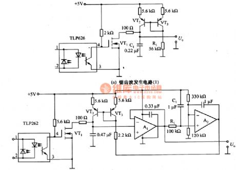
This figure is sawtooth wave generating circuit synchronous with industrial frequency power.6-67(a) is awtooth wave generating circuit synchronous with industrial frequency power composed of current mirror.R1 is used to adjust the slope of the waveform.Voltgae two ports of C1 output in original sawtooth wave way so the high impedance circuit is connected.
The picture (b) is sawtooth wave generating circuit whose amplitude is constant when the input frequency is changed.R1 and C1 make sawtooth wave smooth, it makes the feedback on the current mirror composed of VT2 and VT3 after A2's comparasion.This circuit fits for industrial frequency,50HZ/60HZ and air or aviation equipment's 400HZ and its corresponding scope is 40 to 400 HZ and its frequency range is very wide. (View)
View full Circuit Diagram | Comments | Reading(696)
10HZ ~100 kHZ White and Pink Noise Generating Circuit
Published:2011/7/9 1:04:00 Author:Michel

The picture is 10HZ~ 100kHZ white and pink noise generating circuit.This is a generating circuit who has 10HZ~100kHZ plain frequency characteristics white noise and -3 dB/oct spectrum pink noise. If white noise is put into the sample,the output signal spectrum is measured and the transmission properties of the sample can be obtained.When the measured
system contains mechanical system,there will be resonance between the measured system and a particular frequency if sine wave scans measured system,which will destroy the sample.Thus usually,white noise is used.In the audio measurement noise signal is also used and when measured system contains the speaker, the power is high if white noise is used and it's high
frequency. (View)
View full Circuit Diagram | Comments | Reading(2586)
Simple Temperature Measurement Circuit of Thermistor
Published:2011/7/9 21:58:00 Author:Michel | Keyword: Thermistor, Temperature Measurement Circuit
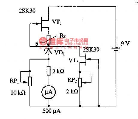
This picture is a simple temperature measurement circuit composed of thermistor.In the circuit,VT1 is self-biased constant current source circuit and it provides constant current for thermistors RT. The measured temperature is standed for 500μA and measuring temperature rage is 0一5O℃.Measuring method:2.538kΩ ordinary resistance substitutes for RT and RP1 is adjusted to make the header instruction become largest and RP2 is regulated to make the header instruction become zero.Then 0.4422 k Ω ordinary resistance substitutes for RT and RP1 is regulated to make the header instruction become full scale.Please adjust it again and again until we get the satisfying value. (View)
View full Circuit Diagram | Comments | Reading(1201)
White Nosie Generator Circuit of Shift Register and Exclusive-OR Gate
Published:2011/7/9 22:28:00 Author:Michel | Keyword: Shift Register, Exclusive-OR Gate, White Nosie, Generator Circuit
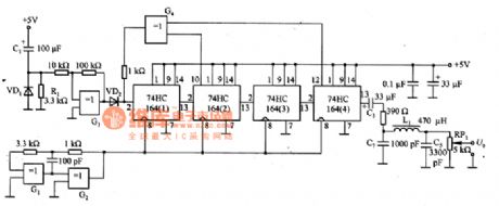
The picture is the white noise generator circuit of shift register and exclusive-or gate.R1 and C1 constitute differential circuit and the circuit enters work state when the switch is turned on.R2, R3 and G3 constitute schmidt trigger circuit.Feet 13 output voltgae of 74HC164(4) is binary signal and the low pass filter composed of L1, C5 and C7 makes amplitude probability density function become normal distribution white noise,namely,Gaussian noise.The cut-off frequency of the low pass filter is enough lower than clock frequency (about 3 MHZ).RP1 is used to adjust and outputs U PWL. (View)
View full Circuit Diagram | Comments | Reading(2014)
Function Generator Circuit of 74HCUO4
Published:2011/7/9 22:44:00 Author:Michel | Keyword: Function Generator Circuit
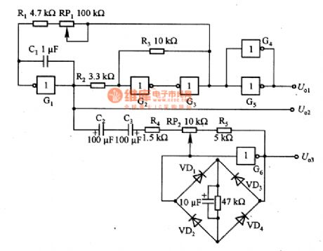
The picture is function generator circuit of 74HCUO4 and G1~G6 is 74HCUO4 inside circuit.This circuit can also output sine wave, rectangular wave and triangle wave at the same time.G1 and C1 constitute Mueller integral circuit and R2, R3, G2 and G3 constitute Schmidt circuit.Output of Schmidt circuit returns to input of miller integral through RP1 and it becomes rectangle wave oscillator. RP1 is used for oscillation frequency adjustment.RP2,R4,R5 and G6 constitute linear inverse amplifier. VD1 ~ VD4 make of diode bridge road and cut top of the triangle wave and turn the triangle wave to sine wave.RP2 adjusts sine wave distortion rate to the minimum value.U.1 outputs rectangle wave,U.2 outputs triangle wave and U.3 outputs sine wave. (View)
View full Circuit Diagram | Comments | Reading(1524)
Temperature Monitoring Circuit of Transistor Temperature Sensor
Published:2011/7/10 19:15:00 Author:Michel | Keyword: Transistor Temperature Sensor, Temperature Monitoring Circuit
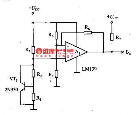
This figure is monitoring circuit of transistor temperature sensor temperature.In the circuit,VT1 is used as temperature snesor,it
adopts the -2·2mV/℃ temperature coefficient of silicon transistors base-emitter voltage and the temperature range is
-65一15O℃. A1 is comparator circuit and its output is U。and is connected with corresponding alarm system.R3 and R4 determine temperature setting value and the warner sounds when the present temperature exceeds setting value. (View)
View full Circuit Diagram | Comments | Reading(3929)
Portable Silicon Voltage Stabilizing Tube Regulation Circuit
Published:2011/7/7 22:57:00 Author:Michel
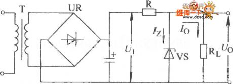
The portable silicon voltage stabilizing tube regulation circuit is shown as above.Welcome to download the circuit and the information is from www.dzsc.com. (View)
View full Circuit Diagram | Comments | Reading(566)
| Pages:374/471 At 20361362363364365366367368369370371372373374375376377378379380Under 20 |
Circuit Categories
power supply circuit
Amplifier Circuit
Basic Circuit
LED and Light Circuit
Sensor Circuit
Signal Processing
Electrical Equipment Circuit
Control Circuit
Remote Control Circuit
A/D-D/A Converter Circuit
Audio Circuit
Measuring and Test Circuit
Communication Circuit
Computer-Related Circuit
555 Circuit
Automotive Circuit
Repairing Circuit