
Basic Circuit
Index 360
74 series of digital circuit, 74143,74144 4-bit counter / latch, seven-segment LED / lamp driver
Published:2011/7/24 4:32:00 Author:Lucas | Keyword: 74 series , digital circuit, 4-bit counter , 4-bit latch, seven-segment LED , lamp driver
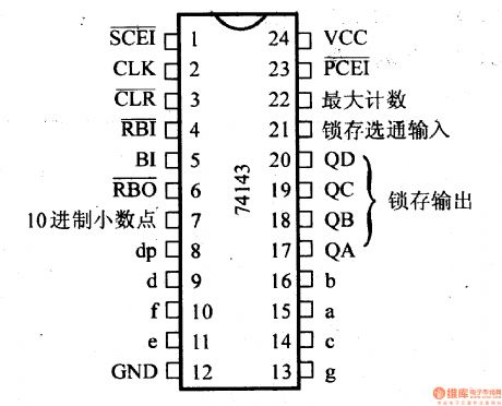
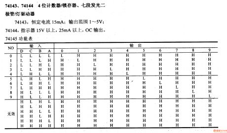
The constant current of 74143 is 15mA, and the output range is 1-5V; the indicating voltage of 74144 is above 15V, and current is more than 25mA with OC output. 74145 functional table
(View)
View full Circuit Diagram | Comments | Reading(2348)
74 series digital circuit of 74LS424 two-phase clock generator/driver
Published:2011/7/21 3:24:00 Author:Lucas | Keyword: 74 series , digital circuit , two-phase clock generator, two-phase clock driver
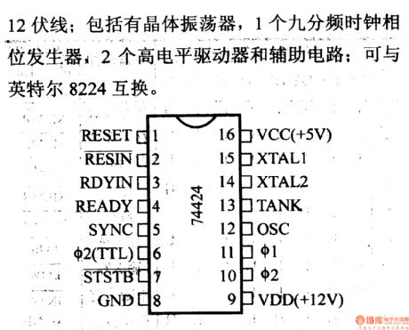
It is used to drive all 8080A microprocessors and 12V lines; it includes crystal oscillator, a nine-frequency clock phase generator, 2 high-level driver and auxiliary circuit; it can exchange with the Intel 8224.
(View)
View full Circuit Diagram | Comments | Reading(1134)
Motor vehicle low temperature starter
Published:2011/7/20 19:10:00 Author:Lucas | Keyword: Motor vehicle , low temperature , starter
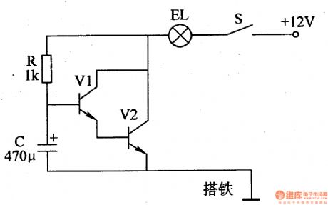
The motor low temperature starter circuit consists of control switch S, resistors Rl-R3, capacitor C, transistor V, and time-base integrated circuit IC, and the circuit is shown in Figure 7-175. In the circuit, IC, and Rl, R2, C forme 40OHz pulse oscillator circuit; V and R3 form electronic switching circuit. Rl-R3 select 1/4W metal film resistors. C uses the monolithic capacitors or polyester capacitors. V uses 3DDl5D or 3DDlO2D silicon NPN transistor. IC chooses NE555 time-base integrated circuit. S selects small toggle switch with contact current in 5A.
(View)
View full Circuit Diagram | Comments | Reading(587)
Electric Bicycle electronic governor
Published:2011/7/20 19:17:00 Author:Lucas | Keyword: Electric Bicycle , electronic governor
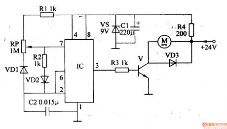
The electric bicycle electronic governor circuit is composed of the regulator filter circuit, pulse oscillation circuit, electronic switching circuit, and the circuit is shown in Figure 7-171. Regulator filter circuit is composed of the resistor R4, Zener diode VS and filter capacitor C1. Pulse oscillation circuit is composed of the resistors Rl, R2, potentiometer RP, diodes VDl, VD2, capacitor C2 and time-base integrated circuit ICl. Electronic switching circuit is composed of the resistor R3, transistor V and diode VD3. Rl-R3 select 1/4W metal film resistors; R4 selects the 1/2W metal film resistor.
(View)
View full Circuit Diagram | Comments | Reading(2507)
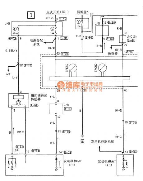
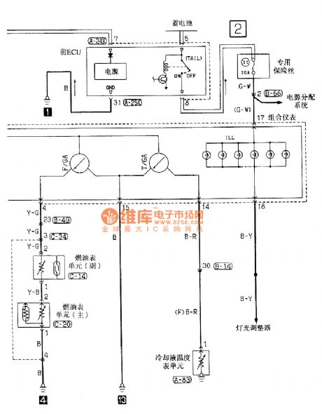
Southeast Ling Sheng instrument electric system circuit
Published:2011/7/20 21:40:00 Author:leo | Keyword: Instrument, electric system
View full Circuit Diagram | Comments | Reading(986)
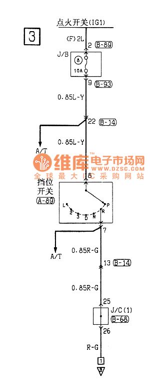
Southeast Ling Sheng dormer electric system circuit
Published:2011/7/20 21:50:00 Author:leo | Keyword: Dormer, electric system

View full Circuit Diagram | Comments | Reading(787)
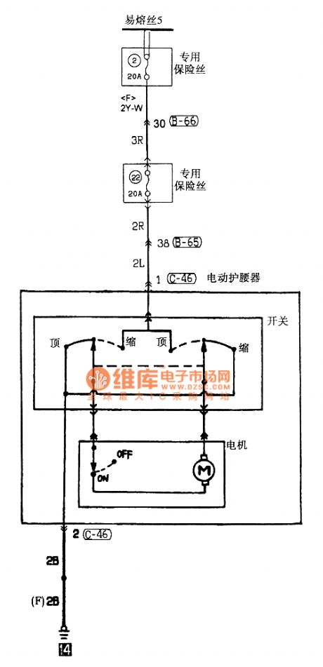
Southeast Ling Sheng waist-protecting appliance electric system circuit
Published:2011/7/20 21:54:00 Author:leo | Keyword: Waist-protecting appliance, electric system
View full Circuit Diagram | Comments | Reading(661)
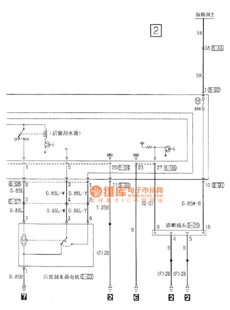
Southeast Ling Sheng rear window wiper and washer electric system circuit
Published:2011/7/20 21:58:00 Author:leo | Keyword: Rear window wiper and washer, electric system

View full Circuit Diagram | Comments | Reading(748)
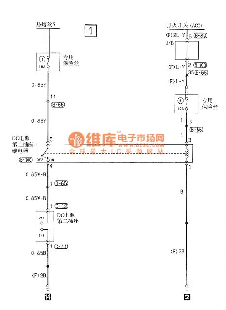
Southeast Ling Sheng the second power socket electric system circuit
Published:2011/7/20 22:01:00 Author:leo | Keyword: Power socket, electric system
View full Circuit Diagram | Comments | Reading(714)
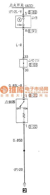
Southeast Ling Sheng cigarette lighter electric system circuit
Published:2011/7/20 23:32:00 Author:leo | Keyword: Cigarette lighter, electric system
View full Circuit Diagram | Comments | Reading(722)
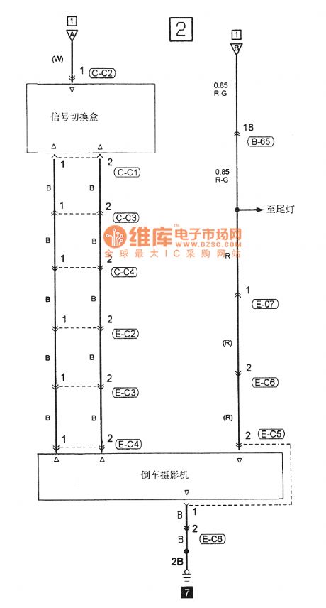
Southeast Ling Sheng car backing camera electric system circuit
Published:2011/7/20 21:21:00 Author:leo | Keyword: Car backing camera, electric system
View full Circuit Diagram | Comments | Reading(797)
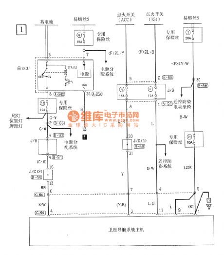
Southeast Ling Sheng mobile radio electric system circuit
Published:2011/7/20 21:24:00 Author:leo | Keyword: Mobile radio, electric system
View full Circuit Diagram | Comments | Reading(730)
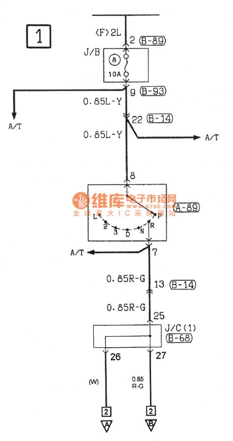
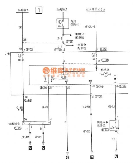
Southeast Ling Sheng key checking buzzer electric system circuit
Published:2011/7/20 21:34:00 Author:leo | Keyword: Key checking buzzer, electric system
View full Circuit Diagram | Comments | Reading(781)
straw feed grinder control circuit
Published:2011/7/19 23:18:00 Author:chopper | Keyword: feed grinder, control circuit
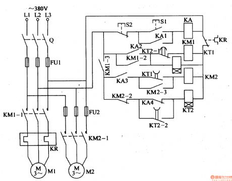
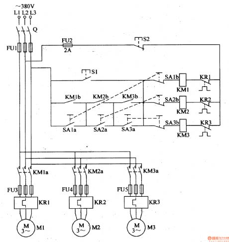
This example describes the straw feed grinder control circuit,which can automatically control the working status of two electric motors. The principle of circuit The straw feed grinder control circuit is formed by knife switch Q,fuses FU1,FU2,thermal relay,AC contactors KM1,KM2,time relays KT1,KT2, intermediate relay KA and control buttons S1,S2,which is shown in Figure 4-129. The main loop of cropping motor M1 is formed thermal components like the normal open main contact KM1-1,KR of Q,FU1,KM1. The main loop of feed motor M2 is formed by normal open main contact KM2-1 of KM2 and Q,FU1,FU2.
(View)
View full Circuit Diagram | Comments | Reading(2170)
fluid resistance cabinet tanks
Published:2011/7/12 5:14:00 Author:chopper | Keyword: fluid resistance cabinet tanks
The fluid resistance cabinet tanks our company produced are reliable, affordable.Welcome new and old customers to discuss. (View)
View full Circuit Diagram | Comments | Reading(443)
oil crop screening and compaction controller
Published:2011/7/19 23:42:00 Author:chopper | Keyword: oil crop, screening, compaction controller
The oil crop(such as soybean,peanut,etc.) of rural small oil mill will be loaded to screening machine to sift through bucket conveyor before oil expression.After removing impurities,the crop will be loaded to the rolling billet machine,and then parch and squeeze the semifinished product.This example describes the oil crop screening and compaction controller,which can uses a start button to start the conveyor, screening machine and the motor of rolling billet simultaneously,and it can also choose a certain motor by controlling button.The operation is very easy. (View)
View full Circuit Diagram | Comments | Reading(641)
seedlings growth stimulator in seedling house
Published:2011/7/19 23:20:00 Author:chopper | Keyword: seedlings, growth stimulator
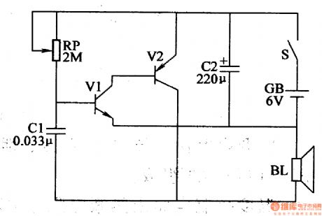
This example describes the seedlings growth stimulator in seedling house,and it is set in the middle of the seedling house which is based on that plants are more sensitive to low-frequency pulse.Thus,users can stimulate the seedlings with its low-frequency pulse,and promote the growth of seedlings.Users can test a small area first, and then put into operation based on the practical situation. The principle of circuitThis seedlings growth stimulator circuit consists of transistors V1,V2,potentiometer RP,capacitors C1,C2,speaker BL,battery GB and power supply switch S which is shown in figure 4-209.
(View)
View full Circuit Diagram | Comments | Reading(614)
wire break informing device of rural cablecasting circuit
Published:2011/7/19 23:37:00 Author:chopper | Keyword: cablecasting, wire break, informing device
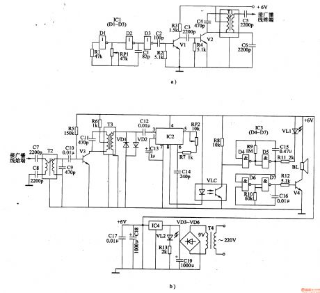
The principle of circuitThe wire break informing device of rural cablecasting circuit is formed by the carrier transmitter circuit,the carrier receiving circuit, alarm circuit and power supply circuit,which is shown in figure 4-212. Carrier transmitter circuit (installed in the terminal of cable broadcasting line) is formed by the high-frequency oscillator and amplified output circuit.The high-frequency oscillator is formed by non-gate D1,D2,resistor R1,capacitor C1 and potentiometer RP1 which are in the non-gate integrated circuit IC1 (D1-D3);and the amplified output circuit is formed by the non-gate D3,capacitors C2-C6,transistor V1,V2,resistors R2, R3 and intermediate-frequency transformer T1 that are in the non-gate D3.
(View)
View full Circuit Diagram | Comments | Reading(878)
An air-conditioning board
Published:2011/7/22 1:26:00 Author:Ecco | Keyword: air-conditioning board
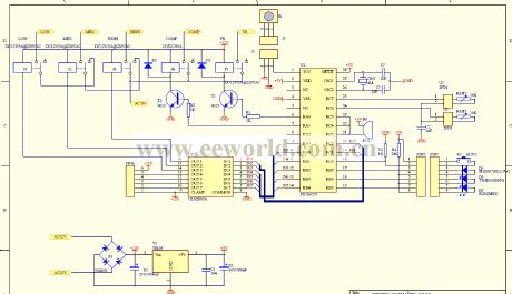
View full Circuit Diagram | Comments | Reading(964)
Battery Automatically and Low Voltage Shut-off Circuits
Published:2011/7/19 11:14:00 Author:Michel | Keyword: Battery Automatically, Low Voltage Shut-off
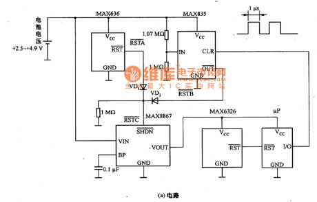
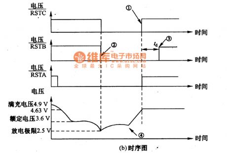
The picture a and b are battery automatically and low voltage shut-off circuits.Without setting procedures and artificial control ,this circuit has the automatically and low voltage shut-off functions. 2.3 V lag voltage can ensure microprocessor uP I/O pins charging detection, battery threshold monitoring and open circuit control.The circuit has low power consumption and the current that the power management current absorbs from power is less than 200 μA when it is loaded fully.When it reaches current discharging point,the circuit shut-off output separates battery and load to prevent battery deep discharging. (View)
View full Circuit Diagram | Comments | Reading(603)
| Pages:360/471 At 20341342343344345346347348349350351352353354355356357358359360Under 20 |
Circuit Categories
power supply circuit
Amplifier Circuit
Basic Circuit
LED and Light Circuit
Sensor Circuit
Signal Processing
Electrical Equipment Circuit
Control Circuit
Remote Control Circuit
A/D-D/A Converter Circuit
Audio Circuit
Measuring and Test Circuit
Communication Circuit
Computer-Related Circuit
555 Circuit
Automotive Circuit
Repairing Circuit