
Basic Circuit
Index 348
VIDEO_FADER
Published:2009/6/19 4:50:00 Author:May
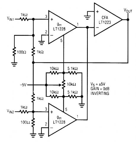
Using two LT1228 transconductance amplifiers in front of a current feedback amplifier forms a video fader. The ratio of the set currents into pin 5 determines the ratio of the inputs at the output. (View)
View full Circuit Diagram | Comments | Reading(2)
1_kW_10_kHz_SINE_WAVE_INVERTER
Published:2009/6/19 4:49:00 Author:May
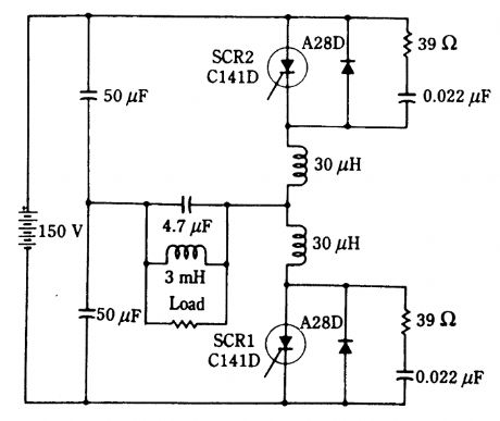
SCRs can produce considerable power at frequencies up to 30 kHz or more. This circuit can supply 1 kW at 10 kHz. The load is shown as an equivalent load, and practically this will be the primary of the transformer for isolation purposes. The power supply can be a 120-V bridge rectifier and filter combination. (View)
View full Circuit Diagram | Comments | Reading(860)
POSITIVE_TO_NEGATIVE_dc_dc_INVERTER
Published:2009/6/19 4:48:00 Author:May
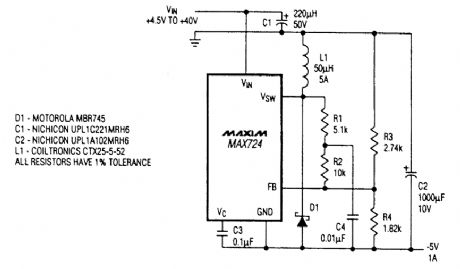
If a source of negative 5 Vdc is needed and only a positive supply is available, this circuit can be used. (View)
View full Circuit Diagram | Comments | Reading(900)
SCR_INVERTER_AND_TRIGGER_CIRCUIT
Published:2009/6/19 4:47:00 Author:May
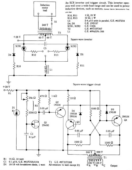
In this circuit, L1 and C5 are used as commutating elements. L1 resonates quency corresponding to the half period of the waveform. (View)
View full Circuit Diagram | Comments | Reading(1069)
TWO_INPUT_VIDEO_MULTIPLEX_CABLE_DRIVER
Published:2009/6/19 4:45:00 Author:May
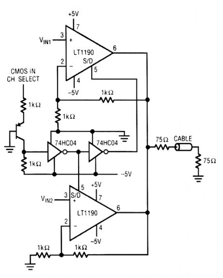
CMOS logic levels select one of two video in-puts with this circuit. The op amps are Linear Technology LT1190s (View)
View full Circuit Diagram | Comments | Reading(827)
MULTIPLE_INPUT_VIDEO_MULTIPLEX_CABLE_DRIVER
Published:2009/6/19 4:44:00 Author:May
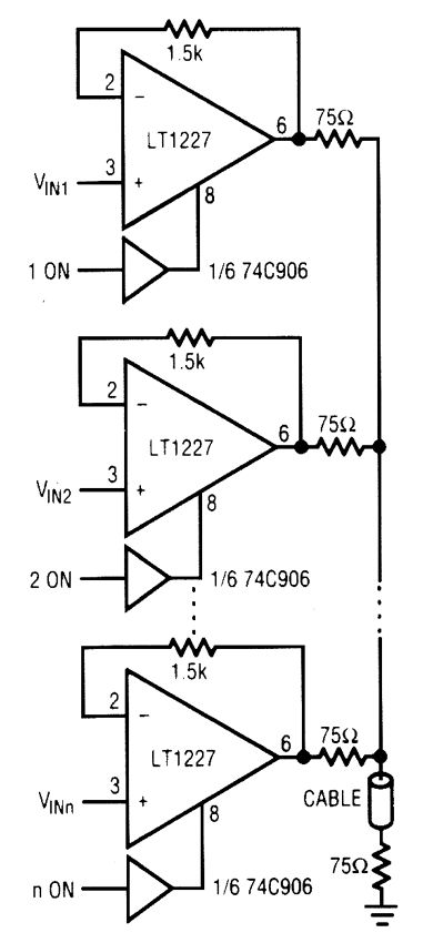

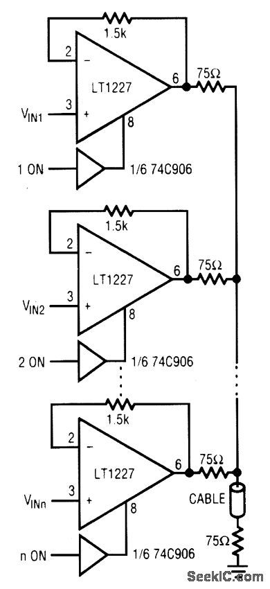
Using a Linear Technology LT1227, the mul-tiplex video amp uses logic levels to tum on and off selected inputs. (View)
View full Circuit Diagram | Comments | Reading(782)
TIMER_ac_LINE_INTERFACE
Published:2009/6/19 4:43:00 Author:May
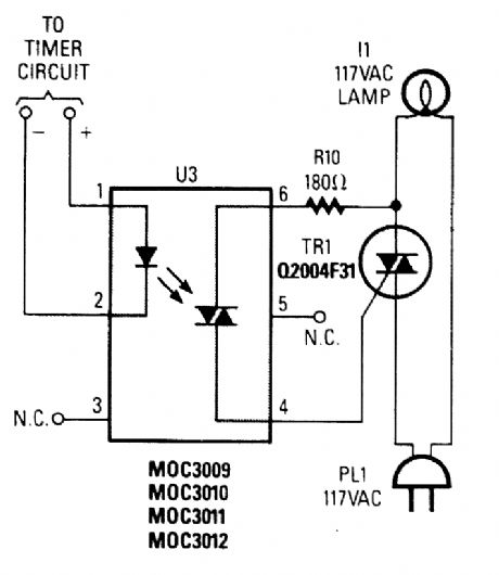
This circuit illustrates the use of an optoisolator to enable the control of a triac connected to the ac line and load, while maintaining dc and ac isolation between the ac line and the timer circuit. A 555 or other timer circuit can be used. (View)
View full Circuit Diagram | Comments | Reading(3263)
ac_INTEGRATOR
Published:2009/6/19 4:41:00 Author:May
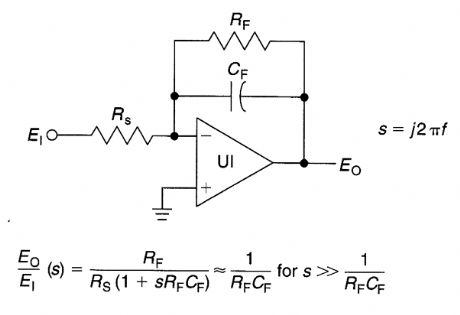
This op-antp circuit can be used with a wide variety of op amps. The values of Rf and Ri depend on gain, but will be 1 kΩ to 1 MΩ in most cases. Cf depends on the pole frequency needed. U1 is a 741-type op amp, etc. (View)
View full Circuit Diagram | Comments | Reading(1750)
SOIL_HEATER_FOR_PLANTS
Published:2009/6/19 4:41:00 Author:May
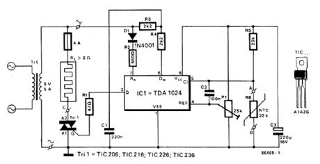
A TDA1024 electronic thermostat senses soil temperature via thermistor R6. The circuit uses zero-crossing switching of the heater. The heater is made of elastic-coated steel wire. P1 is used to set the temperature. The heater should have 2 Ω or more resistance and operate from the 9-V transformer. About 40W of heat is available. (View)
View full Circuit Diagram | Comments | Reading(3865)
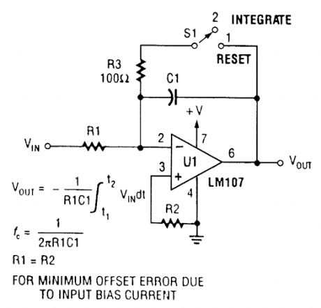
SIMPLE_INTEGRATOR
Published:2009/6/19 4:40:00 Author:May
View full Circuit Diagram | Comments | Reading(734)
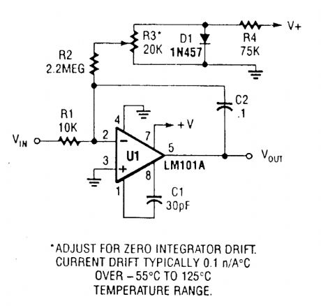
INTEGRATOR_WITH_BIAS_CURRENT_COMPENSATION
Published:2009/6/19 4:39:00 Author:May
View full Circuit Diagram | Comments | Reading(2)
FOUR_INPUT_MINIMUM_MAXIMUM_SELECTOR
Published:2009/6/19 4:34:00 Author:May
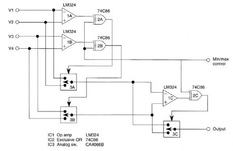
This circuit outputs the maximum (or the minimum) of the four input voltages V1, V2, V3, and V4. Each of these input voltages is in the range 0 to 5V.
The output of the unit is the maximum of V1, V2, V3, and V4 if the control voltage input is 5V (i.e., logical 1). The output is the minimum of V1, V2, V3, and V4 if the control input is zero.
By cascading N such units, one can select the maximum (or the minimum) of 3N + 1 input voltages.
Thus if k is the number of input voltages, we need [(k+1)/3] units. (View)
View full Circuit Diagram | Comments | Reading(898)
4_TO_20_mA_PROCESS_CONTROLLER
Published:2009/6/19 4:27:00 Author:May
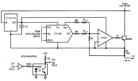
The figure shows how to use an LTC1453 to make an optoisolated digitally controlled 4-to 20-mA process controller. The controller circuitry, including the optoisolator, is powered by the loop voltage that can have a wide range of 3.3V to 30V. The 1.22-V reference output of the LTC1453 is used for the 4-mA offset current and VOUT is used for the digitally controlled 0-to 16-mA current. RS, is a sense resistor and the LT1077 op amp modulates the transistor Q1 to provide the 4-to 20-mA current through this resistor. The control circuitry consumes well under the 4-mA budget at zero scale. (View)
View full Circuit Diagram | Comments | Reading(1314)
ULTRASONIC_GLEANER
Published:2009/6/19 4:18:00 Author:May
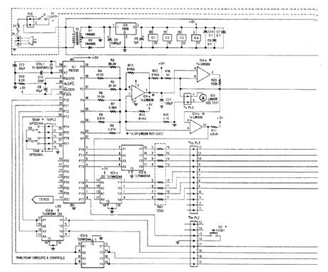
An ultrasonic cleaner is useful to clean certain items. This circuit uses a microcontroller to con-trol timing and give a digital readout, but only the basic oscillator can be used, if desired. RES1, RES2 are piezoelectric transducers driven by power oscillator Q1. Q1 is powered by a bridge rectifier-capacitor input filter that operates directly off the ac line. The frequency is 40 to 60 kHz. (View)
View full Circuit Diagram | Comments | Reading(11275)
WHEEL_OF_FORTUNE
Published:2009/6/19 3:48:00 Author:May
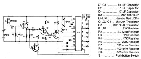
The oscillation of Q2 is amplified by Q3 and fed to Johnson counter IC1. The output of IC1 drives the LEDs in sequence to give the impression of a spinning red ball. (View)
View full Circuit Diagram | Comments | Reading(4)
DIGITAL“FIRST_TO_RESPOND”BOX
Published:2009/6/19 3:44:00 Author:May
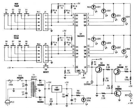
This device is useful for quizzes and games to determine first response. U1 is an octal D type latch IC, an 74LS373.When a button is pushed, this circuit lights the corresponding LED. Q1 conducts, sounding an alarm (BZ1) connected to driver Q3, and Q1 supplies bias to Q2, disabling the rest of the latches in U1. (View)
View full Circuit Diagram | Comments | Reading(936)
voltage follower circuit composed of the μA709
Published:2011/6/27 20:49:00 Author:Rebekka | Keyword: voltage follower
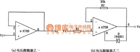
Figure (a) shows the circuit of the voltage follower. It is a special case of the inverting amplifier circuit. The basic relationship of the circuit is: Vi + Vis = Vo Vo =-AVis formula: A - open loop voltage gain operation; Vis - pure op amp input voltage; In the circuit, when the voltage amplitude of the input signal increased to the op amp's positive supply voltage, the deadlock may occur, ie the output signal will not work properly which is due to the internal positive feedback op amp has a parasitic oscillation. To prevent this phenomenon, you can use (b). (View)
View full Circuit Diagram | Comments | Reading(488)
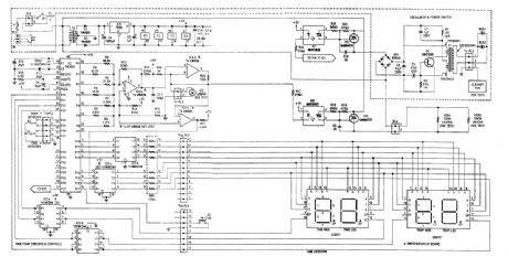
ELECTRONIC_ONE_ARM_BANDIT
Published:2009/6/19 3:42:00 Author:May
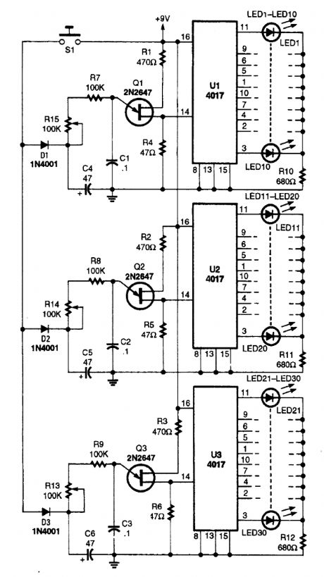
The one-arm bandit circuit is made up of three clock circuits and three counter/readout circuits.A single roll switch, 51, turns on all three clocks at the same time. When S1 is closed, capacitors C4, C5, and C6 are charged through D31, D32, and D33 to about 8 V. After S1 is released, the three clocks run, taking energy from the three charged capacitors. As the capacitors discharge, the three clocks begin to slow down, producing the effect of the drums in a mechanical bandit slowing to a stop.The 4017's 10-output LEDs can be numbered or designated as apples, cherries, bells, wild cards, or anything you like to make the game more interesting. Additional logic circuitry can be added to the 4017 outputs to sound an alert or turn on a light when any three numbers or output items match.Three potentiometers, R12, R13, and R14, can be varied for each roll to change the clock's fre-quency and the roll rate. (View)
View full Circuit Diagram | Comments | Reading(2501)
ELECTRONIC_COIN_TOSS
Published:2009/6/19 3:40:00 Author:May
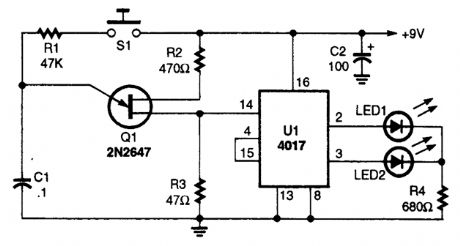
Integrated circuit U1 is connected in a two-stage counter circuit that counts one-two over and over as long as clock pulses enter pin 14 of the 4017. When the clock pulses stop, one of the LEDs will remain on, indicating the last even or odd count. Designate one LED as heads and the other as tails and you have an electronic coin flipper. (View)
View full Circuit Diagram | Comments | Reading(1315)
Z_DICE_GAME
Published:2009/6/19 3:38:00 Author:May
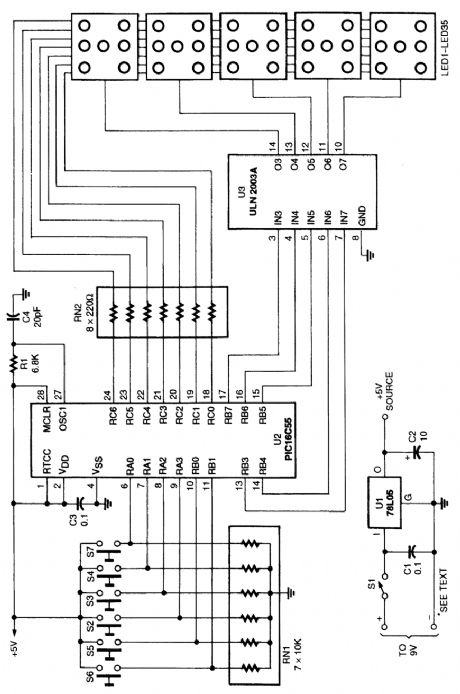
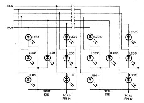
Using a microcontroller (U2) keeps the parts count and the cost of this 5-dice LED display relatively low. Z-dice uses five clusters of seven LEDs to represent the marks or pips on five dice. Buttons below each of the LED dice let the player mark a die to be rolled on the next throw. Marked dice show up as dimmed LEDs. Pressing the button to the right of the display rolls the marked dice. If the player changes his or her mind about rolling a particular die before pressing the roll button, he or she can un-mark it by pressing its button a second time. If no dice are marked at the time the player presses the roll button, then all of the dice are marked to be rolled. A second press starts them rolling, animating the LEDs of the marked dice for a second or so before displaying the results of the roll. Z-Dice doesn't count rolls or keep score, so it's still up to the players to make sure that nobody cheats!This diagram shows the wiring details of the dice display. For space and simplicity, only the first and last dice are shown. A programmed microcontroller is needed for this circuit. Refer to the original article for software. (View)
View full Circuit Diagram | Comments | Reading(1356)
| Pages:348/471 At 20341342343344345346347348349350351352353354355356357358359360Under 20 |
Circuit Categories
power supply circuit
Amplifier Circuit
Basic Circuit
LED and Light Circuit
Sensor Circuit
Signal Processing
Electrical Equipment Circuit
Control Circuit
Remote Control Circuit
A/D-D/A Converter Circuit
Audio Circuit
Measuring and Test Circuit
Communication Circuit
Computer-Related Circuit
555 Circuit
Automotive Circuit
Repairing Circuit